manuals.online logo
Brands
  1. Home
  2. •
  3. Brands
  4. •
  5. Micro
  6. •
  7. Industrial Equipment
  8. •
  9. Micro VT-04 User manual

Micro VT-04 User manual

MICROTESTMACHINES Co.
Automated dipper mechanism
VT-04
microtm.com
2
Installation of VT-04 mechanism
Complete set of automated dipper mechanism VT-04 includes the dipping unit (with embedded control cable), control
electronic unit, set of cables for connecting the electronic unit to electric mains (220-240 V 50 Hz) and to host PC (USB AmBm
cable). Additional accessories are vertical stand (rod on flat base) for mounting the dipping unit, metal arm with PTFE clamp for
the object hanging and extension set of plastic arm that may be used either instead of metal arm or as an extension arm if
attached to the metal arm.
Dipping unit
Arm
PTFE clamp
Vertical rod (stand)
Extension arm
Base plate
USB AmBm cable
Power cord 220-240 V
Control electronic unit
Control cable
embedded in the dipper
Delivery set of automated dipper mechanism VT-04
Arm attached to the
carriage
Clamp to fix the
dipping unit on
vertical rod
A knob for manual
turning of the
driving axis
PTFE clamp to hold
an object
Fixing screw in the
clamp
Vertical rod (stand)
to mount the
dipping unit
Base plate
A mounting block on
movable carriage
Embedded control
cable
The unit case
Elements of the dipping unit
3
Some minor assembling will be necessary after the unpacking the delivery set.
1. Screw vertical rod into a hole on base plate
2. Mount the dipping unit on the vertical rod (stand) and fix its position with a fixing screw in
the clamp.
3. Using two screws attach arm to the mounting block of movable carriage.
4. Adjust position of vertical element with PTFE clamp on the arm if necessary.
After dipping unit assembly, connect the embedded control cable from the dipper to socket on rear side of control electronic unit.
And connect the control electronic unit to host PC with the USB AmBm cable from the set. Using power cord, connect the
control electronic unit to electrical network (220…240 V 50 Hz).
4
Installation of software to run VT-04
The automated dipper mechanism VT-04 operates under control from host PC. Connection of control electronic unit with
host PC is provided via USB-port emulating COM-port.
Official site to download latest drivers for USB-to-COM system: https://www.ftdichip.com/FTDrivers.htm.
It may appear that old versions of the drivers fit your host PC better. Some old releases are also available at:
http://microtm.com/download/CDM_v2.12.24_WHQL_Certified.zip
http://microtm.com/download/CDM2.08.30WHQLCertified.zip
http://microtm.com/download/CDM2-12-18.RAR
http://microtm.com/download/CDMv2.10.00WHQLCertified.exe
To install USB-to-COM drivers, unpack the driver installation pack in a temporary folder on hard disk and switch on the
device (control electronic unit). After this first turning on, host PC will find new device and ask for drivers. Provide the driver
installation wizard with correct path to the driver installation pack in a temporary folder and system will be installed.
After the USB-to-COM driver installation check number of port that system assigned for the new device. Open branch
‘Ports (COM & LPT)’ in the computer Device Manager (Control panel – System – Device manager):
and remember the number of newly appeared device entitled ‘USB Serial Port (COM#)’, for example, COM9 as in the picture
below.
To run the dipper from host PC use specialized program that is available for download from:
http://microtm.com/download/vt-04_ctrl_inst.zip
This archive is an installation package. Please, unpack it in an empty temporary folder on the computer hard disk and run file
setup.exe. After finishing the setup procedure, control program can be started with conventional ways used in Windows.
5
Control program for VT-04
VT-04 control program panel and its elements are shown in the figure below:
COM-port selector
Button to connect/
disconnect the device
and host PC
Activity indicator
Upper point
calibration button
Pane to set speed
under manual mode
Area for hardware
settings indication
Pane to set travel distance
under manual mode
Manual control area Programmable motion area
Absolute coordinate
of soft 0 position
Current absolute
coordinate of the
carriage
Button to set
current position
as soft 0
Number of remaining cycles
Start/Stop button for
programmable motion
Pane to set number of cycles
Current coordinate
of the carriage
relatively soft 0
Graphic indicator
of soft 0 position
Graphic indicator
of the carriage
current position
Parameters for upward motion
Parameters for
downward motion
[The program start]
Before the control program start, switch the control electronic unit on. After switching the hardware on, wait a couple of
seconds and start the control program. In the folder where the control program was installed, run executable file ‘serial.exe’.
In the control program panel, firstly, select correct COM-port in the port selector (corresponding to ‘USB Serial Port
(COM#)’ in Device Manager). Secondly, press button ‘OPEN RS232’ to connect the device with host PC. About correct
connection system will notify you with label “Device found / dipper control board ready!!!’:
and the port connection button will change color to green with inscription ‘CLOSE RS232’.
Note: If correct connection was not installed, check number of the selected COM-port and repeat the program start procedure
waiting more between the device switching on and the control program start.
Example of the program panel after the device connection is shown below
6
[Upper point calibration]
Upper point calibration should be performed at first run of the device, after positioning of the carriage with knob on the
dipper top and after moving the carriage with service buttons on control electronic unit when system does not trace performed
steps (distances). To start the upper point calibration procedure, press button ‘INIT UP POSITION’ and wait till carriage reach its
upper position and stop with limit switch.
[Manual operation mode]
For simple vertical motion of the dipper arm for certain distance you may use manual control option – buttons ‘UP’ and
‘DOWN’ in ‘MANUAL CONTROL’ area. Distance of vertical displacement of the carriage (arm) after pressing corresponding
button is set in pane ‘Z moving, mm’. Indicator ‘steps’ automatically shows number of steps that the stepper motor performs to
cover the distance. Speed of the arm (carriage) translation is set in pane ‘Z speed, mm/sec’. Numbers in the panes throughout
the program panel may be entered by typing them in the pane or searching with the small up and down buttons left to the pane.
Motion with the preset parameters will start at pressing button ‘UP’ or ‘DOWN’ after which the activated button will
change color to red (see figure below). To stop the motion before full distance covering, press the active button again or press
spacebar on the keyboard of the host PC.
7
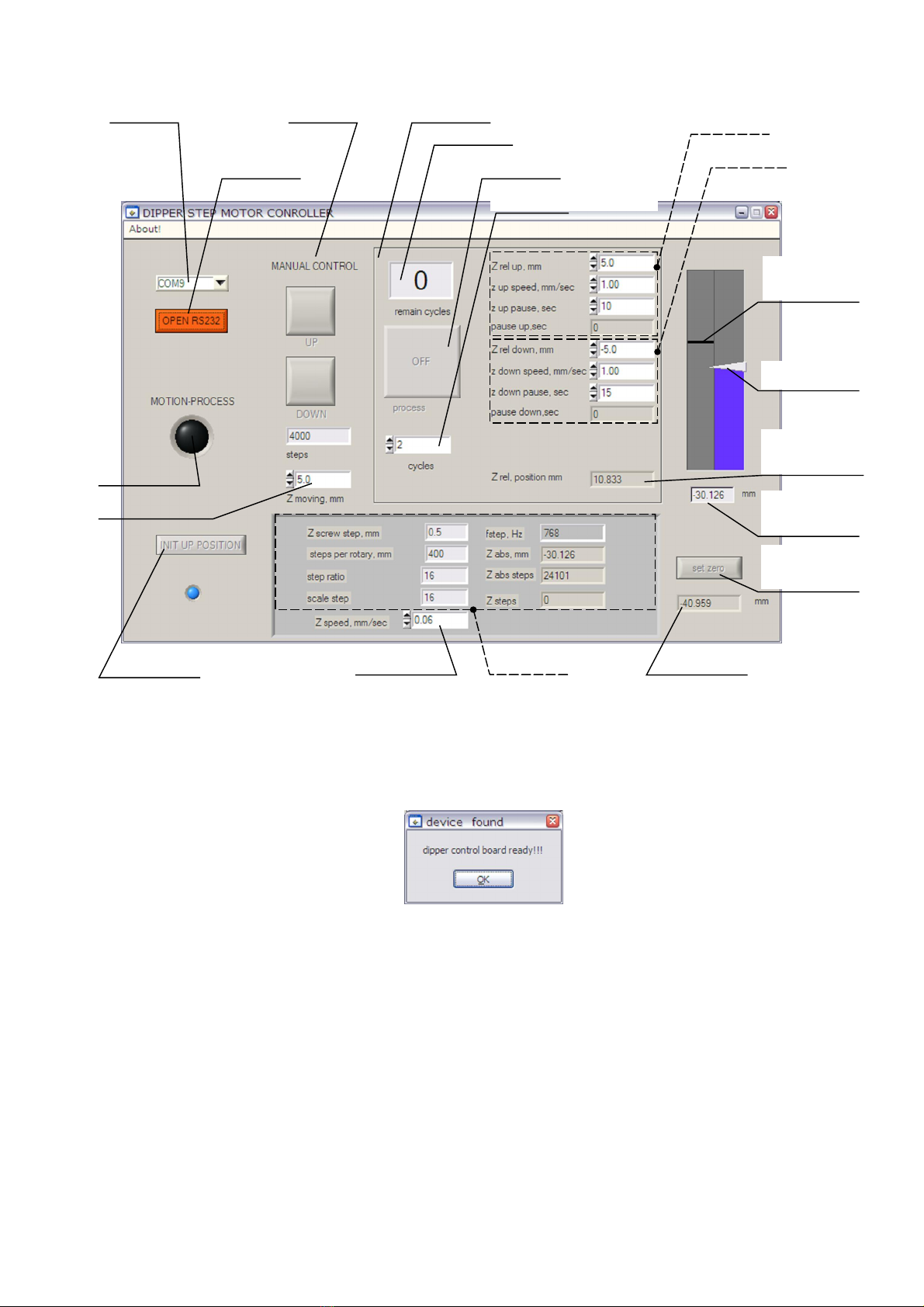
Using buttons of manual control you may, for example, position the arm with attached object at necessary height (e.g.
liquid in a vessel) and then set this position as soft 0 by pressing button ‘set zero’. That will simplify assignment of coordinates
for the object dipping and lifting under programmable operation mode.
[Programmable operation mode]
Automated dipper VT-04 provides possibility for multicycle operation with preset parameters separately for upward and
downward movement of the arm (carriage). All necessary parameters should be set in Programmable motion area of the control
program panel (see example below).
Enter in pane ‘cycles’ number of dipping/lifting cycles planned to perform. Other parameters are as follows:
Z rel up, mm – coordinates of upper point (relatively cutrrent soft zero) of the carriage cycle motion.
z up speed, mm/sec – speed at which the arm (carriage) will travel upward to the position set by ‘Z rel up, mm’.
z up pause, sec – pause in movement that will be performed by the mechanism in upper point of the cycle (set by
‘Z rel up, mm’).
pause up, sec – counter for pause performed in upper point of the cycle; the counter starts when the pause begins.
Z rel down, mm – coordinates of lower point (relatively current soft zero) of the carriage cycle motion.
z down speed, mm/sec – speed at which the arm (carriage) will travel downward to the position set by ‘Z rel down, mm’.
z down pause, sec – pause in movement that will be performed by the mechanism in lower point of the cycle (set by
‘Z rel down, mm’).
pause down, sec – counter for pause performed in lower point of the cycle; the counter starts when the pause begins.
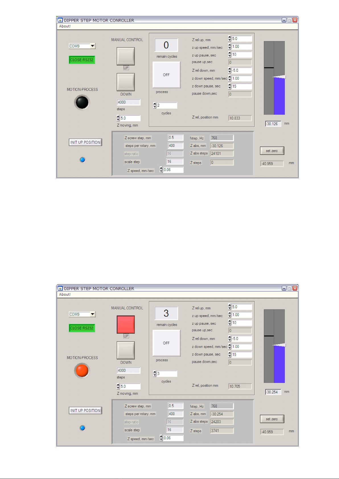
To start the programmable motion with the preset parameters, press ‘process’ button (with inscription ‘OFF’ in its middle
showing its current state). The cycle process will start and the button change color to green (inscription in the button middle will
change to ‘ON’). Note that buttons in manual control area will change their state correspondingly to currently performed motion,
i.e. when carriage goes down button ‘DOWN’ comes to activated state (red color). If carriage goes up, button ‘UP’ comes to
activated state (red color). You may stop the process fulfillment by pressing the activated buttons or spacebar on the host PC
keyboard.
[Exiting program]
Before exiting the control program it is recommended to disconnect from the device by pressing button ‘CLOSE RS232’.
It is recommended to disconnect from the device before switching the control electronic unit off as well.

Popular Industrial Equipment manuals by other brands

ABB HT610288 Operation manual

ABB

ABB HT610288 Operation manual

Novexx Solutions XLP 51 Series user manual

Novexx Solutions

Novexx Solutions XLP 51 Series user manual

SEW-Eurodrive CMS quick start guide

SEW-Eurodrive

SEW-Eurodrive CMS quick start guide

ABB HT562676 Operation manual

ABB

ABB HT562676 Operation manual

ATOMSTACK MAKER R1 manual

ATOMSTACK

ATOMSTACK MAKER R1 manual

Edwards Iron Worker quick start guide

Edwards

Edwards Iron Worker quick start guide

FrontLine 10SS-NA Operation manual

FrontLine

FrontLine 10SS-NA Operation manual

PCM P03-GDF-516 operating instructions

PCM

PCM P03-GDF-516 operating instructions

sauter EY-RU110 quick reference

sauter

sauter EY-RU110 quick reference

ABB HT562674 Operation manual

ABB

ABB HT562674 Operation manual

Trox Technik X-AIRCONTROL FAM-RD Installation and operating manual

Trox Technik

Trox Technik X-AIRCONTROL FAM-RD Installation and operating manual

WEISS ROBOTICS GRIPLINK manual

WEISS ROBOTICS

WEISS ROBOTICS GRIPLINK manual

ABB HT612462 Operation manual

ABB

ABB HT612462 Operation manual

ABB HT567585 Operation manual

ABB

ABB HT567585 Operation manual

LNS Super Hydrobar HS Series instruction manual

LNS

LNS Super Hydrobar HS Series instruction manual

Mesdan JOINTAIR 115 manual

Mesdan

Mesdan JOINTAIR 115 manual

Enerpac Pull-pac BRP106C instruction sheet

Enerpac

Enerpac Pull-pac BRP106C instruction sheet

Neopost RENA XPS-ProMail 3.0 user guide

Neopost

Neopost RENA XPS-ProMail 3.0 user guide

manuals.online logo
manuals.online logoBrands
  • About & Mission
  • Contact us
  • Privacy Policy
  • Terms and Conditions

Copyright 2025 Manuals.Online. All Rights Reserved.