INDUSTRIES, INC.
INDUSTRIES, INC.
Si nce 1982
GripSafe Patents:
US – 9,927,058, 9,810,364 | CA – 3,004,787 | European Registration – 00626264-0001
Other US and Foreign Patents Pending
www.USAIndustries.com | (713) 941-3797
©2019, USA Industries, Inc.
FRM-23.1 Rev.B
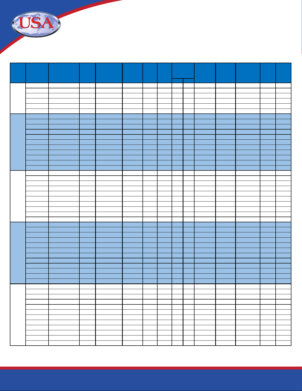
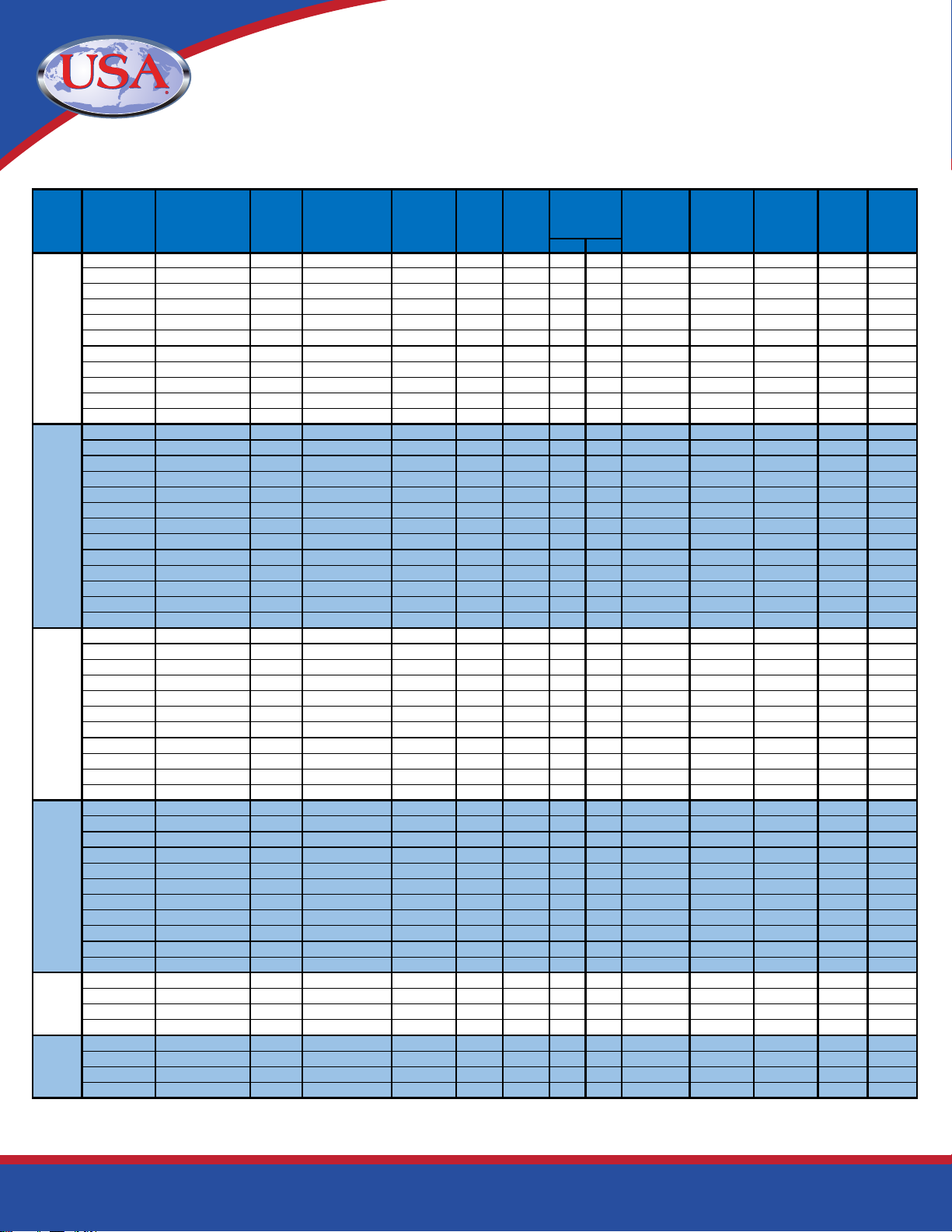
Table 2: GripSafe DBB Specications Continued
Page 9of 24
Norm Max.
10S GS-D-S-1600-010S 15.25 15.311 - 15.735 0.375 212 15.12 265 420 1-5/8" 1/4" FNPT 1" MNPT 1950 2500
10 GS-D-S-1600-010 15.13 15.187 - 15.611 0.375 210 15.12 255 395 1-5/8" 1/4" FNPT 1" MNPT 1975 2500
20 GS-D-S-1600-020 15.00 15.063 - 15.486 0.375 206 15.12 245 370 1-5/8" 1/4" FNPT 1" MNPT 2000 2500
30,STD,40S GS-D-S-1600-STD 14.88 14.937 - 15.360 0.375 199 15.12 230 350 1-5/8" 1/4" FNPT 1" MNPT 2025 2500
40,XS,80S GS-D-S-1600-XS 14.63 14.687 - 15.108 0.375 192 15.12 200 305 1-5/8" 1/4" FNPT 1" MNPT 2100 2500
60 GS-D-S-1600-060 14.31 14.375 - 14.795 0.375 192 15.12 205 315 1-5/8" 1/4" FNPT 1" MNPT 2200 2500
80 GS-D-S-1600-080 14.00 14.063 - 14.481 0.375 188 15.12 200 305 1-5/8" 1/4" FNPT 1" MNPT 2300 2500
100 GS-D-S-1600-100 13.56 13.625 - 14.041 0.375 188 15.12 195 295 1-5/8" 1/4" FNPT 1" MNPT 2350 2500
120 GS-D-S-1600-120 13.19 13.249 - 13.663 0.375 182 15.12 185 285 1-5/8" 1/4" FNPT 1" MNPT 2400 2500
140 GS-D-S-1600-140 12.75 12.811 - 13.223 0.375 182 15.12 180 275 1-5/8" 1/4" FNPT 1" MNPT 2500 2500
160 GS-D-S-1600-160 12.44 12.499 - 12.909 0.375 178 15.12 175 270 1-5/8" 1/4" FNPT 1" MNPT 2525 2500
10S GS-D-S-1800-010S 17.25 17.311 - 17.745 0.375 270 15.12 395 605 1-5/8" 1/4" FNPT 1" MNPT 1725 2500
10 GS-D-S-1800-010 17.13 17.187 - 17.621 0.375 265 15.12 380 580 1-5/8" 1/4" FNPT 1" MNPT 1750 2500
20 GS-D-S-1800-020 17.00 17.063 - 17.496 0.375 260 15.12 365 555 1-5/8" 1/4" FNPT 1" MNPT 1775 2500
STD,40S GS-D-S-1800-STD 16.88 16.937 - 17.370 0.375 254 15.12 345 530 1-5/8" 1/4" FNPT 1" MNPT 1800 2500
30 GS-D-S-1800-030 16.75 16.811 - 17.243 0.375 250 15.12 330 505 1-5/8" 1/4" FNPT 1" MNPT 1825 2500
XS,80S GS-D-S-1800-XS 16.63 16.687 - 17.118 0.375 247 15.12 315 480 1-5/8" 1/4" FNPT 1" MNPT 1850 2500
40 GS-D-S-1800-040 16.50 16.563 - 16.994 0.375 245 15.12 295 450 1-5/8" 1/4" FNPT 1" MNPT 1975 2500
60 GS-D-S-1800-060 16.25 16.311 - 16.740 0.375 240 15.12 290 440 1-5/8" 1/4" FNPT 1" MNPT 2025 2500
80 GS-D-S-1800-080 15.75 15.811 - 16.238 0.375 235 15.12 280 425 1-5/8" 1/4" FNPT 1" MNPT 2100 2500
100 GS-D-S-1800-100 15.31 15.375 - 15.800 0.375 230 15.12 270 415 1-5/8" 1/4" FNPT 1" MNPT 2175 2500
120 GS-D-S-1800-120 15.08 15.137 - 15.561 0.375 225 15.12 265 405 1-5/8" 1/4" FNPT 1" MNPT 2175 2500
140 GS-D-S-1800-140 14.50 14.563 - 14.984 0.375 224 15.12 255 390 1-5/8" 1/4" FNPT 1" MNPT 2275 2500
160 GS-D-S-1800-160 14.06 14.125 - 14.543 0.375 219 15.12 245 375 1-5/8" 1/4" FNPT 1" MNPT 2350 2500
10S GS-D-S-2000-010S 19.19 19.249 - 19.693 0.375 330 15.32 325 510 1-5/8" 1/4" FNPT 1-1/2" MNPT 1550 2500
10 GS-D-S-2000-010 19.13 19.187 - 19.631 0.375 324 15.32 320 495 1-5/8" 1/4" FNPT 1-1/2" MNPT 1550 2500
20,STD,40S GS-D-S-2000-STD 18.88 18.937 - 19.380 0.375 317 15.32 295 450 1-5/8" 1/4" FNPT 1-1/2" MNPT 1600 2500
30,XS,80S GS-D-S-2000-XS 18.63 18.687 - 19.128 0.375 308 15.32 270 410 1-5/8" 1/4" FNPT 1-1/2" MNPT 1650 2500
40 GS-D-S-2000-040 18.44 18.499 - 18.939 0.375 298 15.32 250 380 1-5/8" 1/4" FNPT 1-1/2" MNPT 1850 2500
60 GS-D-S-2000-060 18.00 18.063 - 18.501 0.375 292 15.32 240 370 1-5/8" 1/4" FNPT 1-1/2" MNPT 1875 2500
80 GS-D-S-2000-080 17.56 17.625 - 18.061 0.375 285 15.32 235 360 1-5/8" 1/4" FNPT 1-1/2" MNPT 1925 2500
100 GS-D-S-2000-100 17.06 17.125 - 17.558 0.375 278 15.32 230 350 1-5/8" 1/4" FNPT 1-1/2" MNPT 2000 2500
120 GS-D-S-2000-120 16.63 16.687 - 17.118 0.375 281 15.32 220 340 1-5/8" 1/4" FNPT 1-1/2" MNPT 2050 2500
140 GS-D-S-2000-140 16.12 16.183 - 16.612 0.375 270 15.32 215 330 1-5/8" 1/4" FNPT 1-1/2" MNPT 2075 2500
160 GS-D-S-2000-160 15.69 15.751 - 16.178 0.375 259 15.32 210 320 1-5/8" 1/4" FNPT 1-1/2" MNPT 2125 2500
10,10S GS-D-S-2400-010 23.13 23.187 - 23.651 0.375 431 15.32 395 600 1-5/8" 1/4" FNPT 1-1/2" MNPT 1300 2500
20,STD,40S GS-D-S-2400-STD 22.88 22.937 - 23.400 0.375 422 15.32 360 555 1-5/8" 1/4" FNPT 1-1/2" MNPT 1325 2500
XS,80S GS-D-S-2400-XS 22.63 22.687 - 23.148 0.375 414 15.32 330 505 1-5/8" 1/4" FNPT 1-1/2" MNPT 1350 2500
30 GS-D-S-2400-030 22.50 22.563 - 23.024 0.375 409 15.32 320 490 1-5/8" 1/4" FNPT 1-1/2" MNPT 1550 2500
40 GS-D-S-2400-040 22.25 22.311 - 22.770 0.375 400 15.32 315 485 1-5/8" 1/4" FNPT 1-1/2" MNPT 1575 2500
60 GS-D-S-2400-060 21.69 21.749 - 22.206 0.375 382 15.32 310 470 1-5/8" 1/4" FNPT 1-1/2" MNPT 1625 2500
80 GS-D-S-2400-080 21.19 21.249 - 21.703 0.375 388 15.32 300 460 1-5/8" 1/4" FNPT 1-1/2" MNPT 1650 2500
100 GS-D-S-2400-100 20.56 20.625 - 21.076 0.375 374 15.32 290 445 1-5/8" 1/4" FNPT 1-1/2" MNPT 1700 2500
120 GS-D-S-2400-120 20.00 20.063 - 20.511 0.375 372 15.32 285 435 1-5/8" 1/4" FNPT 1-1/2" MNPT 1725 2500
140 GS-D-S-2400-140 19.50 19.563 - 20.009 0.375 366 15.32 275 420 1-5/8" 1/4" FNPT 1-1/2" MNPT 1750 2500
160 GS-D-S-2400-160 18.94 18.999 - 19.442 0.375 360 15.32 265 410 1-5/8" 1/4" FNPT 1-1/2" MNPT 1825 2500
10,10S GS-D-S-3000-010 29.00 29.063 - 29.556 0.375 679 15.32 275 420 1-5/8" 1/4" FNPT 1-1/2" MNPT 900 2500
STD,40S GS-D-S-3000-STD 28.88 28.937 - 29.430 0.375 673 15.32 260 400 1-5/8" 1/4" FNPT 1-1/2" MNPT 900 2500
XS,80S GS-D-S-3000-XS 28.63 28.687 - 29.178 0.375 661 15.32 240 370 1-5/8" 1/4" FNPT 1-1/2" MNPT 900 2500
30 GS-D-S-3000-030 28.38 28.437 - 28.927 0.375 650 15.32 205 315 1-5/8" 1/4" FNPT 1-1/2" MNPT 900 2500
10 GS-D-S-3600-010 35.00 35.063 - 35.586 0.375 989 15.32 295 455 1-5/8" 1/4" FNPT 1-1/2" MNPT 625 2500
STD,40S GS-D-S-3600-STD 34.88 34.937 - 35.460 0.375 982 15.32 285 435 1-5/8" 1/4" FNPT 1-1/2" MNPT 625 2500
XS,80S GS-D-S-3600-XS 34.63 34.687 - 35.208 0.375 968 15.32 260 395 1-5/8" 1/4" FNPT 1-1/2" MNPT 625 2500
30 GS-D-S-3600-030 34.38 34.437 - 34.957 0.375 954 15.32 250 385 1-5/8" 1/4" FNPT 1-1/2" MNPT 625 2500
30
36
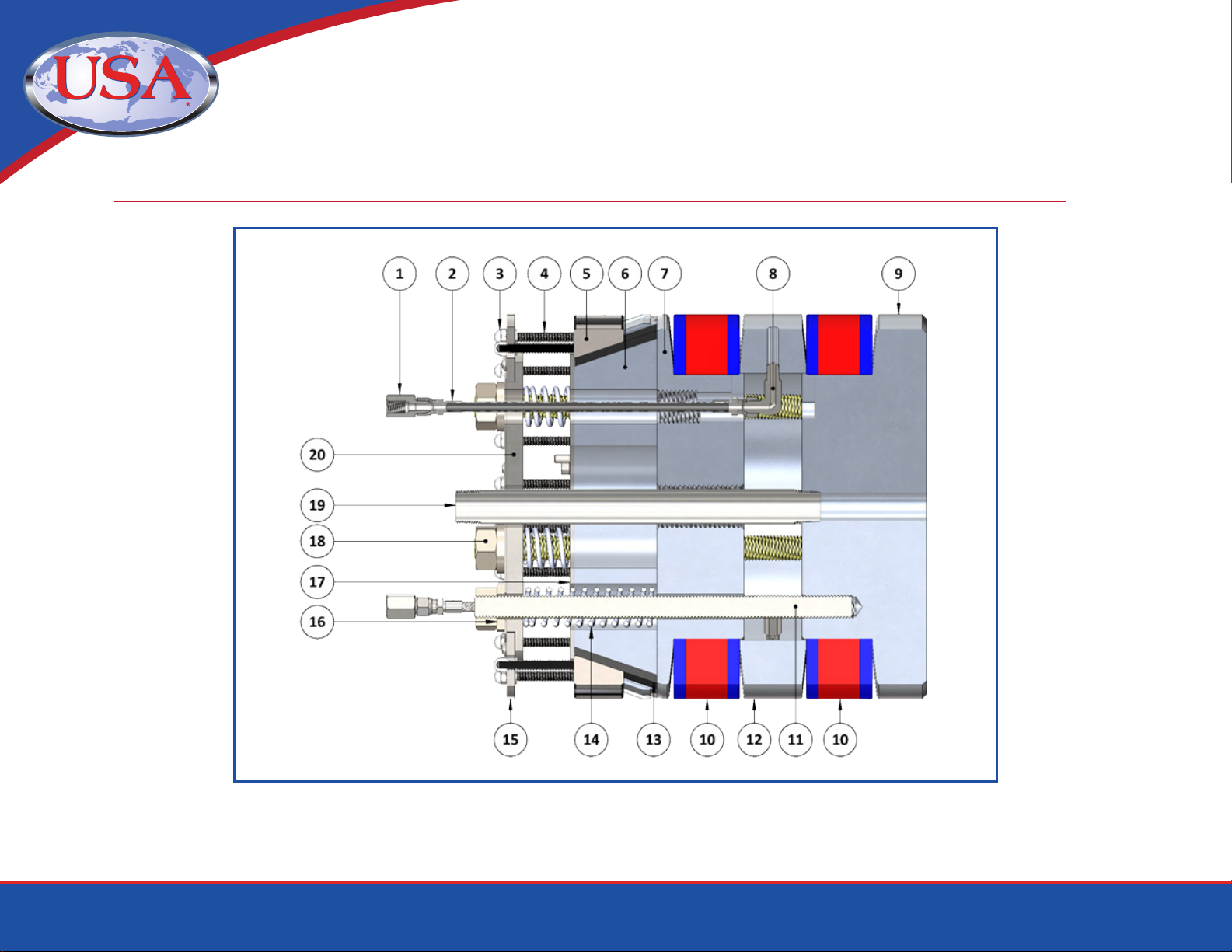
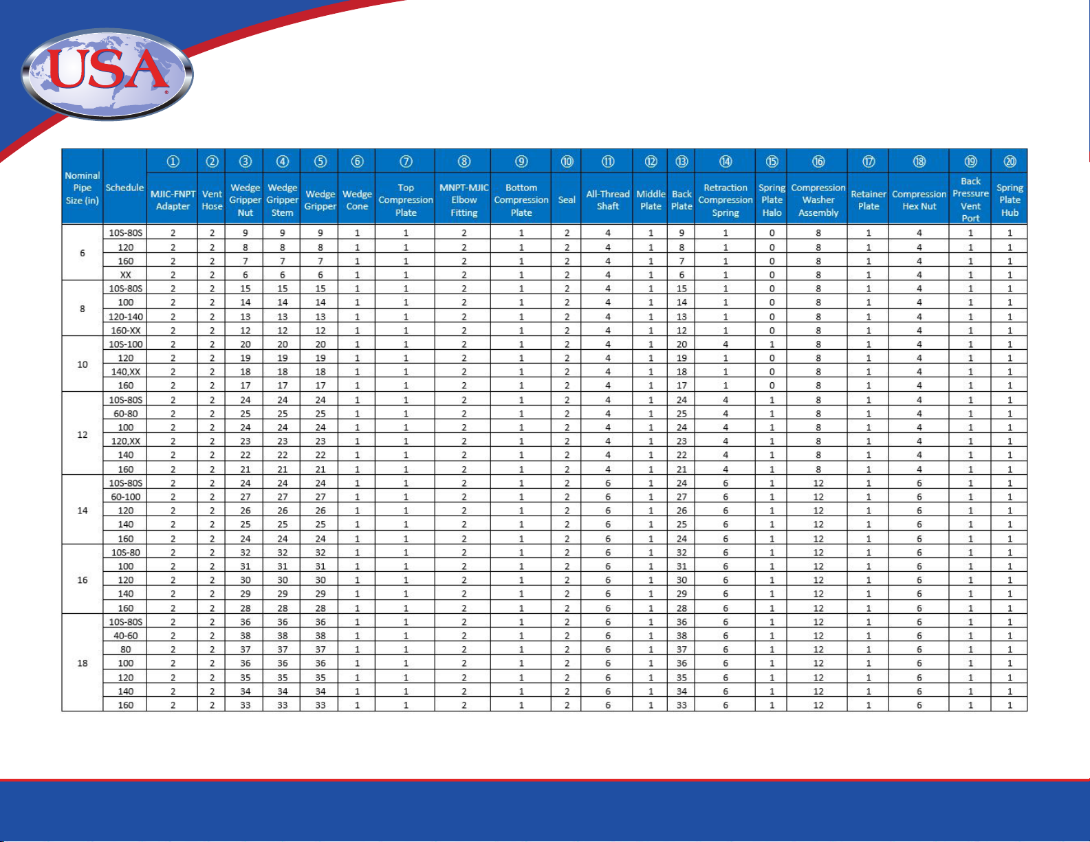
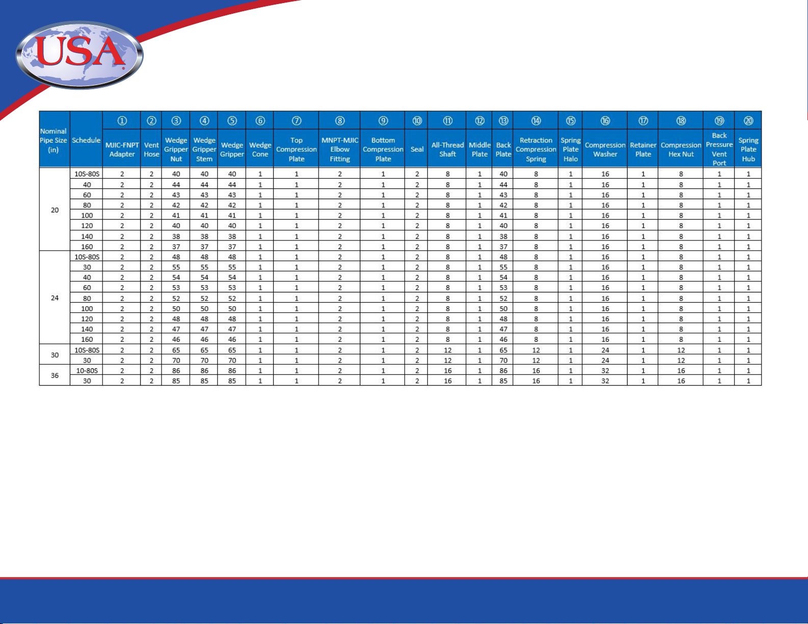
Part Number
Rec.
ID Range*
(in)
Approx.
Tool Weight
(lbs)
24
18
20
Nominal Pipe
ID Clearance
(in)
Back
Pressure
Vent Thread
Back
Pressure
Rating
(PSI)
Between the
Seal Test
Pressure
(PSI)
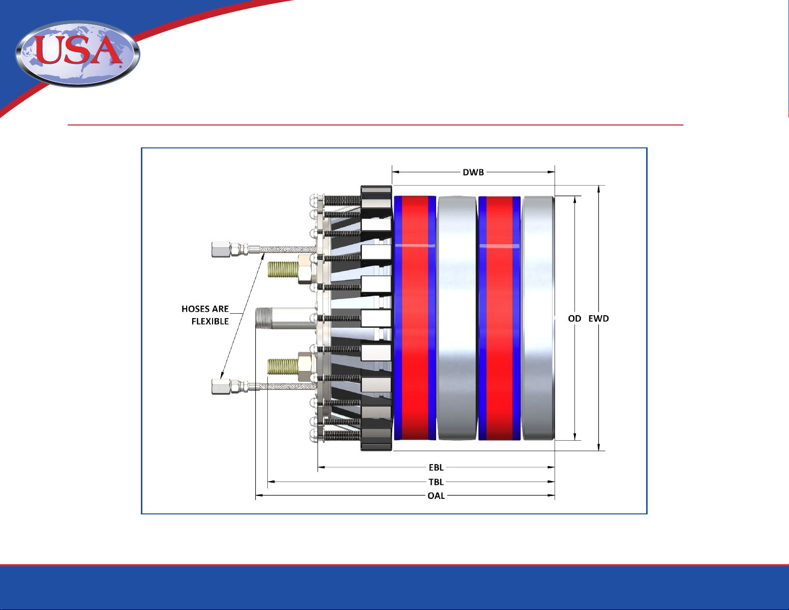
Tool Length
(in)
16
Nominal
Pipe Size
(in)
Schedule Fill & Vent
Port Thread
Tool
Diameter
(in)
Torque Range
(ft-lbs)
Compression Hex
Nut
Socket Size
(in)