AxFlow Aturia NA Series Manual

Single Stage
Mechanically Coupled
End Suction
Centrifugal Pump
built to DIN 25255
standard
NA SERIES
OPERATION
&
MAINTENANCE
MANUAL

IMPORTANT NOTES
NA Series Operating & Instruction Manual Page i
Read these instructions before putting the pump into service.
Installation and operation should be carried out by qualified personnel only.
Danger of electrocution. Electric supply must be isolated before working on the pumpset.
Electrical work should only be carried out by qualified personnel

CONTENTS
NA Series Operating & Instruction Manual Page ii
GENERAL.................................................................................................................................................1
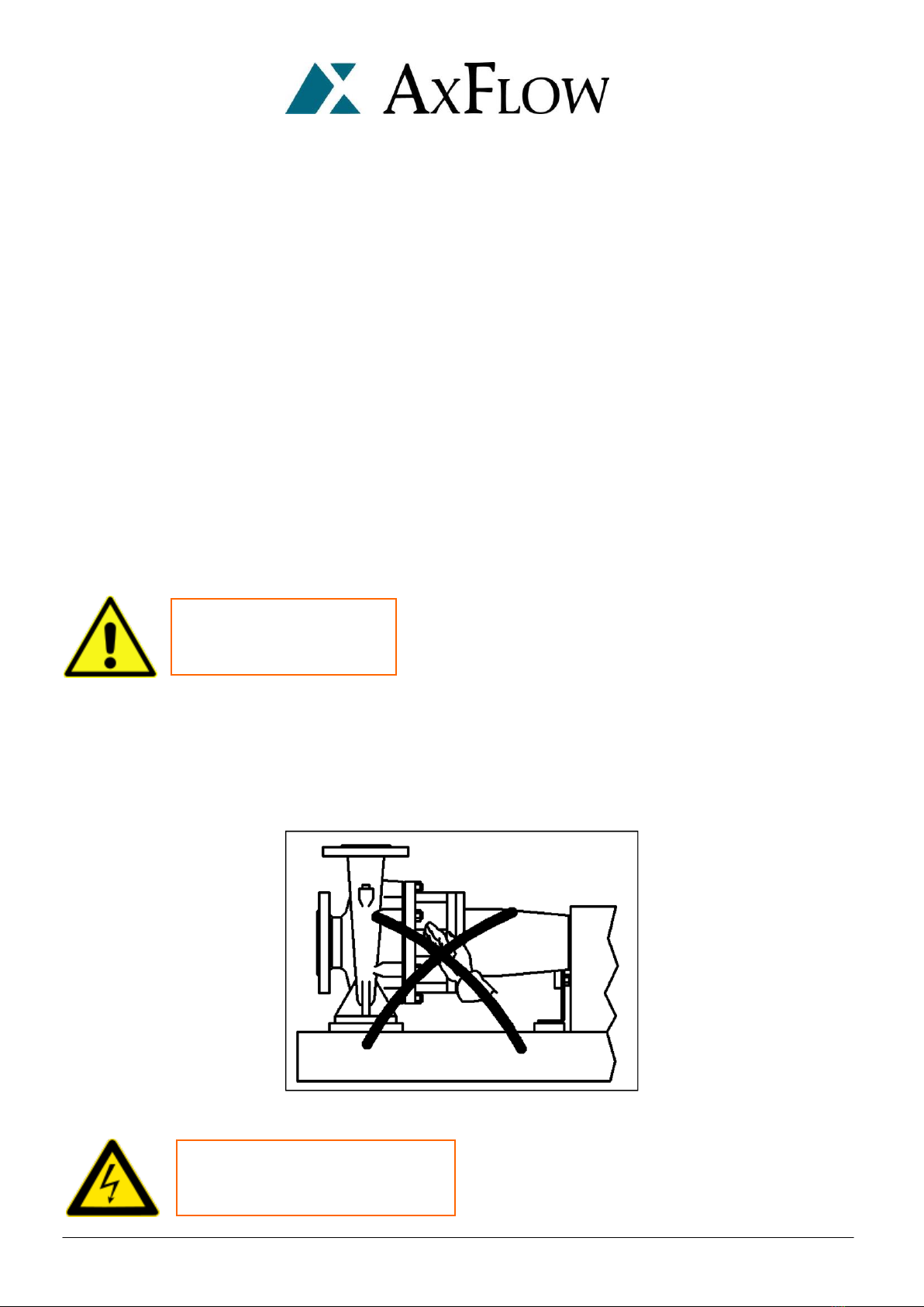
Precautions during operation...............................................................................................................1
Noise levels ..........................................................................................................................................1
Operating limits ...................................................................................................................................2
Residual risks........................................................................................................................................3
In case of emergency............................................................................................................................3
Area of operation .................................................................................................................................4
Spare parts...........................................................................................................................................4
Transport .............................................................................................................................................5
Storage ................................................................................................................................................6
Storage for a period shorter than 3 months......................................................................................6
Storage for a period exceeding 3 months (but shorter than 12 months)...........................................6
Storage (after operation)..................................................................................................................6
Drivers..................................................................................................................................................7
INSTALLATION........................................................................................................................................8
Foundations .........................................................................................................................................8
Motor-pump units on baseplates......................................................................................................8
Pump and motor alignment .................................................................................................................9
Methods of checking alignment.........................................................................................................10
Straight edge..................................................................................................................................10
Dial gauge ("clocking") ................................................................................................................... 11
Optical methods............................................................................................................................. 11
Location and piping............................................................................................................................ 11
Admissible external forces and torques on pump flanges ..................................................................14
Protecting the pump against dry running...........................................................................................15
Loss of liquid supply .......................................................................................................................15
Low inlet pressure .......................................................................................................................... 15
`Dead-heading'...............................................................................................................................15
Electronic dry running protection.......................................................................................................15
Electrical connection..........................................................................................................................16
Connecting the electric motor........................................................................................................16
Oil lubricated...................................................................................................................................... 17
Bearings ......................................................................................................................................... 17
Oil type........................................................................................................................................... 17
Direction of rotation...........................................................................................................................18
OPERATION ..........................................................................................................................................19
Supervision ........................................................................................................................................19
Priming the pump ..............................................................................................................................19
Start-up..............................................................................................................................................20
Pump operation .................................................................................................................................20

CONTENTS
NA Series Operating & Instruction Manual Page iii
MAINTENANCE .....................................................................................................................................22
Supply isolation..................................................................................................................................22
Maintenance schedule .......................................................................................................................22
Gland packing ....................................................................................................................................23
Mechanical seal..................................................................................................................................23
Bearings .............................................................................................................................................23
Grease lubricated ...........................................................................................................................23
Oil lubricated..................................................................................................................................24
Oil type...............................................................................................................................................24
Pump stop for long period..................................................................................................................24
DISASSEMBLY.......................................................................................................................................25
Disassembling the pump....................................................................................................................25
Complete pump disassembling ..........................................................................................................25
Partial pump disassembling ...............................................................................................................25
Support and rotor disassembling .......................................................................................................26
Gland packing inspection ...................................................................................................................26
Mechanical seal inspection.................................................................................................................26
Bearings inspection............................................................................................................................26
REASSEMBLY ....................................................................................................................................27
Before reassembling ..........................................................................................................................27
Reassembling the pump.....................................................................................................................27
Gland packing reassembling ..............................................................................................................27
Mechanical seal reassembling............................................................................................................28
Pump reassembly...............................................................................................................................28
TYPICAL CROSS-SECTION....................................................................................................................29
TROUBLESHOOTING ............................................................................................................................32
DECOMMISSIONING AND DISMANTLING ........................................................................................... 37
NOTES ...................................................................................................................................................38

GENERAL
NA Series Operating & Instruction Manual Page 1
ATTENTION !
GENERAL
AxFlow Aturia NA series pumps are single stage mechanically coupled end suction pumps. Details of
the pump type and model, serial number and operating data are indicated on the pump nameplate.
The pump must be installed and operated in full compliance with these instructions. The pump may not
be operated outside the limits specified on the nameplate and within this manual. The pump should
only be operated by skilled trained personnel. The manufacturer will not accept liability if these
instructions are not followed.
This manual does not take into account any specific local regulations or bylaws that may be applicable,
and it is the responsibility of the installer to ensure compliance with such regulations.
Precautions during operation
Always take the following safety precautions :
The coupling guard must be at its place on the baseplate.
If warm liquids are pumped, protect the pump to prevent contact with warm pump surfaces.
Never put your hands or any kind of object into pump openings where the shaft rotates
(see picture)
Protect motor and all
electric parts according to
current regulations

GENERAL
NA Series Operating & Instruction Manual Page 2
Noise levels
The following table reports the noise level produced by AxFlow Aturia NA series pumps running with in
their operating limits and installed according to the instructions given in this manual (average values
measured in free field at 1 meter from the pump set and elaborated according to ISO standard R1680 –
curve A). The values are referred to groups with AxFlow standard electric motors. For other motors the
table values shall be compared to the actual used motors.
MOTOR
FRAME SIZE
MOTOR SPEED
2 Pole
4 Pole
63
65
65
71
67
65
80
71
65
90
73
67
100
77
69
112
79
70
132
80
71
160
81
72
180M
82
73
180L
82
73
200
83
74
225
84
75
250
85
77
280
86
80
315S
89
83
315M
90
84
355
91
87
400
93
89
Operating limits
The operating limits are the following :
Suction pressure max. 4 bar
Max. operating pressure at delivery max. 10 bar
Pumping liquid temperature max. 130 °C min. –10°C
Performances are described in the technical specification enclosed in the AxFlow order confirmation.

GENERAL
NA Series Operating & Instruction Manual Page 3
DON’T KICK THE PUMP
DON’T DAMAGE THE
PUMP BY MISHANDLING
DON’T PRESSURIZE THE
PUMP BEYOND
RECOMMENDED LIMITS
AVOID DRY RUNNING, OPERATION AT LOWER
CAPACITY THAN ALLOWED OR RUNNING
AGAINST A CLOSED DISCHARGE VALVE
AVOID THERMAL SHOCK
FROM COLD FLUIDS AGAINST
WARM SURFACES
ONLY USE THE PUMP WITH
FLUIDS SPECIFIED IN THE
ORDER DATASHEETS
Residual risks
Inobservance of the safety instructions here reported or improper use of the pump may result in heavy
damage to things and/or injuries to the person.
Always keep to the following directions :
In case of emergency
Switch off line voltage
Warn service personnel responsible of the plant

GENERAL
NA Series Operating & Instruction Manual Page 4
Area of operation
AxFlow Aturia NA series pump sets may be installed within a building or externally. Wherever installed,
protect the pump from frost, snow and flooding.
Care must be taken to ensure that cold weather will not cause the pump or pipes to freeze, and
installers may wish to consider lagging or trace heating.
If supplied, standard electric motors are only suitable for operation in safe areas, free from the danger
of explosive liquids or gases.
Spare parts
Spare parts are available from AxFlow throughout Great Britain. Please quote the pump model and
serial number for all spares enquiries.
The pump user is strongly recommended to carry replacement spares for parts which are wearing items
as follows:
Radial ball bearings
Impeller
Wear ring
Shaft sleeve
Gasket
Mechanical seal or packing , depending on the construction
If an electric motor is supplied as the drive then also include the following:
Pair of motor bearings

GENERAL
NA Series Operating & Instruction Manual Page 5
Transport
Check the nameplate on the pump against the receiving and purchase order documents to be sure that the
correct size of pump and materials of construction have been supplied. If a motor has been supplied, check
that the power, speed, and voltage are correct.
Prior to unpacking, check for physical damage to the packing and the pump unit and notify the forwarding
agent IMMEDIATELY if any damage is found.
Check that the port covers are intact. If not, check whether foreign objects may have found their way into the
pump casing through the ports. Remove the port covers only when you are ready to connect the pipes to the
pump.
When shipped, the pumps are suitable for short-term storage only. If long-term storage is necessary
before the pump will be put into operation, we suggest that you contact your pump supplier for long-
term storage recommendations.
Check for free rotation of the pump. To check long-coupled pumps for free rotation, remove the coupling
guard and rotate the pump and motor shafts at the flexible coupling.

GENERAL
NA Series Operating & Instruction Manual Page 6
Storage
The delivered pump is generally suitable for immediate installation.
Storage for a period shorter than 3 months
Store the pump in a dry and sheltered area.
Check that ambient temperature never falls below 5°C.
It is recommended that the pump shaft is rotated at regular intervals ( every 30 days ): this
prevents damage to the bearings and seizure of the rotating parts.
Storage for a period exceeding 3 months (but shorter than 12 months)
Raise the pump by means of wooden supports.
Open the package, if any, removing the protection from the pump nozzles and clean by
compressed air then carefully dry inside the pump, if necessary.
Protect the pump inside with anti-condensation products and close the flanges so that no
foreign objects can enter the pump.
Cover the pump with a plastic film and put inside some products the prevent water
condensation.
Check protections periodically.
It is recommended that the pump shaft is rotated at regular intervals ( every 30 days ): this
prevents damage to the bearings and seizure of the rotating parts.
Storage (after operation)
In case of long periods after operation, drain the pipes and the pump through the drain hole in
the lower part of the pump casing.
If an electric motor is supplied as the drive, then before putting into service, the motor winding
insulation should be tested. If the reading is below 10 Mega ohms, move to a warm dry place for a few
hours until the motor insulation value rises.

GENERAL
NA Series Operating & Instruction Manual Page 7
Drivers
AxFlow Aturia NA series pumps may be driven by an electric motor through a shaft -to-shaft coupling.
There are particular points which can affect the pump:
Shaft -to-shaft flexible couplings must be properly aligned, as poor alignment will
cause high loads on the pump bearings. Couplings must be suitably rated, and provide
sufficient flexibility to prevent shock forces and oscillating loads from being
transmitted to the pump shaft. This is particularly important for diesel engine drives.
When designing the drive system and prime mover, take into account that the pump
dismantles by removing the rotating element out from the back of the pump casing.
Sufficient space should be allowed to facilitate dismantling of the pump.

INSTALLATION
NA Series Operating & Instruction Manual Page 8
INSTALLATION
Foundations
The foundation should be substantial in order to reduce vibrations, and rigid enough to prevent flexing
which can result in misalignment. Foundation bolts of the correct size should be located by reference
to certified drawings if the baseplate is supplied with the pump.
The pump must be mounted horizontally on a level foundation, with the discharge port vertically
upwards.
The pumpset should be mounted on a level horizontal base. The base should be of sufficient rigidity to
prevent flexing. When bolting the pump down, insert shims as necessary under the pump feet to level
the pump using a spirit level on the suction and discharge flanges of the pump. Use all six bolt holes to
mount the pump.
Motor-pump units on baseplates
Level the baseplate accurately, using shims under the base-plate next to the foundation bolts. The
baseplate must sit firmly and evenly on its foundation: it must not be distorted by bolting to an uneven
surface, which will throw the pump and motor out of alignment.
Isolate the supply
before commencing
work on the pump.

INSTALLATION
NA Series Operating & Instruction Manual Page 9
COUPLING GUARD MUST
BE FITTED ON BASEPLATE
AFTER ALIGNMENT
CHECK THE ALIGNMENT OF
PUMP AND MOTOR PRIOR
TO START-UP
Pump and motor alignment
Long-coupled pumps have been pre-aligned with the motor prior to shipment. If pump units receive
rough treatment during shipment, they can become misaligned. The flexible coupling is not designed
to compensate for misalignment. Improper alignment will cause vibration and premature bearing
failure.

INSTALLATION
NA Series Operating & Instruction Manual Page 10
A final alignment check should be made after the baseplate has been grouted and set, and the
foundation bolts have been tightened.
TYPE
DISPLACEMENT
GAP
Short flexible coupling
(3000 rpm)
0.05 mm
0.04 mm per 100 mm
coupling diameter
Flexible spacer coupling
(3000 rpm)
0.07 mm per
100 mm spacer length
0.04 mm per 100 mm
coupling diameter
Methods of checking alignment
Straight edge
Using a straight edge, check the distance from the shaft at several points on the circumference of the
coupling. The distances d1 and d2 should each remain constant.
IMPORTANT NOTE: The straight edge method checks static coupling alignment, not shaft alignment.
It relies for its accuracy on the accurate alignment of each coupling half on its shaft. The straight edge
method is a useful preliminary check, but should not be seen as an effective final alignment method.

INSTALLATION
NA Series Operating & Instruction Manual Page 11
Dial gauge ("clocking")
There are several methods, using one or two dial gauges. The lost accurate is the reverse indicator
method, using two gauges, which overcomes errors due to `sag' of the gauge bars.
Optical methods
Several proprietary systems are available, such as the `OPTALIGN' system (INA Linear Systems).
Mechanical errors are eliminated by optical alignment techniques. On request, AxFlow can provide
further information about suitable alignment methods, including allowances for THERMAL
EXPANSION IN HIGH TEMPERATURE USE.
Location and piping
The correct pipework sizes should be selected according to the allowable limits of liquid velocity and
pressure drop at the required flow rate. Check the NPSH required by the pump at its specified duty
point, and ensure that the minimum NPSH available exceeds that required.
This is particularly important for liquids near their boiling temperature (or bubble point).
Check that the pipework is THOROUGHLY CLEAN before the pump is installed.
Pipework connections must be accurately aligned with the pump ports, so that they can be connected
to the pump without forcing. Maximum allowable bending moments are set out in the Table overleaf.
These moments must not be exceeded, otherwise the pump may distort internally, or the pump and
motor may become misaligned.
Pipework must be fully and independently supported as close as practicable to the pump.
Locate the pump as close as possible to the liquid source.
The suction line should be as short and straight as possible, with a minimum number of bends. Bends
should be large radius type: avoid sharp elbows. Bends and fittings should be no closer than 20 pipe
diameters to the pump suction, to allow undisturbed flow to the pump impeller. Liquid velocity in the
suction line should normally be between 0.7 and 2.0m/sec. If the liquid is near its boiling temperature
(or bubble point), its velocity may need to be reduced to 0.5-1.0m/sec. If the suction line is oversized,
the reducer at the pump inlet port should be ECCENTRIC, not concentric.
Generally, suction piping should be one or two sizes larger than the inlet bore of the pump, to keep
liquid velocity low and friction losses to a minimum. This becomes more important as the distance
between the pump and the liquid supply increases.
The suction line should slope so as to avoid air pockets.

INSTALLATION
NA Series Operating & Instruction Manual Page 12
ATTENTION !
Valves on the suction side should be mounted with stems horizontal, or vertically downwards. All joints
in the suction line must be tight, to prevent air from entering into the system, with the risk of vapour
locking.
If the pump is installed with a negative static inlet head (lower diagram), the foot valve/ strainer must
always be immersed at a sufficient depth to avoid entry of air into the pump. Take suitable precautions
to prevent vortexing in the supply vessel. A pressure gauge should be installed in the suction line, as
close as possible to the pump.
If the supply vessel is under vacuum, a pressure balancing line should connect the supply vessel and the
pump inlet port.
The discharge line should be as short and direct as possible to minimize friction losses. An air vent (if
permissible) should be installed at the first high point in the discharge line.

INSTALLATION
NA Series Operating & Instruction Manual Page 13
AVOID PUMPING LIQUIDS
CONTAINING
SUSPENDED SOLIDS
A check valve and gate valve should be installed as close as possible to the pump discharge nozzle. The
check valve is installed to protect the pump from excessive back pressure or reverse flow rotation, and
to prevent back flow into the pump during shut down. The discharge (gate) valve is used to regulate the
flow. The check valve should be installed between the pump and the discharge valve to allow the pump
to be removed from service without emptying the discharge line.
A pressure gauge should be installed on the discharge side of the pump as close as possible to the
discharge nozzle.
Prior to starting the pump it is important to flush the piping to make sure that the system is free of
solids such as pipe scale, welding beads, and dirt. If possible a TEMPORARY START-UP STRAINER with
a 40 mesh screen should be installed in the suction line.
BE VERY CAREFUL not to allow the temporary strainer to become plugged, causing low inlet pressure
with cavitation or dry running. A pressure gauge should be installed on either side of the temporary
strainer to measure the pressure drop across it. If there is any risk of ingestion of solids during normal
operation, once the pump has been successfully commissioned, a PERMANENT INLET STRAINER
should be fitted in the inlet line.
Standard AxFlow pumps are designed to handle clean liquids. Unless specifically agreed prior to
purchase of the pump from your supplier, suspended solid matter must be kept out of the pump by a
suitable inlet strainer. The strainer mesh size should be less than 0.5mm, with an open surface area at
least 2.5 x nominal cross-sectional area of pump inlet bore. The strainer must be inspected regularly
and cleaned when necessary.

INSTALLATION
NA Series Operating & Instruction Manual Page 14
x
y
z
x
y
z
Admissible external forces and torques on pump flanges
TYPE
FLANGE
TORQUES, (daN)
MOMENTS, (daN.m)
Fx
Fy
Fz
ΣF
Mx
My
Mz
ΣM
3x12
3x16
3x20
3x25
Suction
45
38
30
70
25
12
20
35
Delivery
32
25
20
45
15
8
10
20
4x12
4x16
4x20
4x25
4x31
Suction
55
45
38
85
38
18
28
50
Delivery
35
28
22
50
18
10
12
25
5x12
5x16
5x20
5x25
5x31
Suction
55
45
38
85
38
18
28
50
Delivery
38
30
22
55
25
12
20
35
6x12
6x16
6x20
6x25
6x31
Suction
70
55
45
100
50
25
38
70
Delivery
45
38
28
70
38
18
28
50
8x16
8x20
8x25
8x31
8x40
Suction
95
75
60
140
75
38
55
100
Delivery
55
45
35
80
50
25
38
70
10x16
10X20
10x25
10x31
10x40
Suction
125
100
85
190
95
50
75
135
Delivery
75
60
48
110
75
38
55
100
12x20
12x25
12x31
12x40
12x50
Suction
165
130
105
240
125
63
95
170
Delivery
100
85
63
150
95
50
75
130
15x20
15x25
15x31
15x40
15x50
Suction
260
200
165
375
190
95
135
250
Delivery
130
105
87
190
125
63
95
170
20x20
20x25
20x31
20x40
20x50
Suction
350
280
230
500
260
130
200
350
Delivery
200
160
125
290
190
95
135
250
25x25
25x31
25x40
25x50
Suction
425
350
300
650
340
175
260
430
Delivery
250
200
150
350
230
120
170
320

INSTALLATION
NA Series Operating & Instruction Manual Page 15
Protecting the pump against dry running
The pump must not be allowed to run dry. Dry running will result in loss of liquid film to the bearings,
causing over-heating and eventual bearing failure, leading to seizure of the pump.
Avoid the following conditions:
Loss of liquid supply
Ensure that an adequate supply of liquid is available at the pump inlet at all times. Pressure and/or flow
sensors should be installed if necessary, to monitor the hydraulic conditions in the inlet pipework.
Low inlet pressure
Low inlet pressure due to restriction or blockage of the inlet pipework, causing liquid vaporization and
cavitation in the pump, with the risk of loss of liquid film in the bearings.
`Dead-heading'
If the pump is permitted to run against a closed discharge for more than a short time (depending on the
liquid, the duty, and the pump model and power), the liquid in the pump casing will heat up and
evaporate with consequences as above.
Electronic dry running protection
A rapid and reliable method of stopping a centrifugal pump, in the event of loss of liquid supply or
interruption of flow, is to monitor the power output of the motor. The `EL-FI' device monitors both
current and phase angle, providing pump protection without pipework sensors or attachments. It is
easily fitted in the power supply to the motor, in place of a normal starter. Details of power monitors
are available on request from your pump supplier.

INSTALLATION
NA Series Operating & Instruction Manual Page 16
Electrical connection
The electrical connection to the motor should be carried out by a properly qualified electrician, using
cable, cable glands and connection procedures suitable for the electrical load and for the location of the
installation.
All regulations governing electrical installations in HAZARDOUS AREAS must be strictly followed. It is
the responsibility of the pump user to ensure that a safe electrical installation is made and maintained.
Connecting the electric motor
1. Isolate the electric supply cable from the power supply.
2. Bring the cable end into the terminal box through a suitable cable gland.
3. Follow the motor manufacturer's instructions for electrical connection. These will normally be
found inside the terminal box, either on a separate instruction sheet or attached to the inside of
the terminal box cover.
Check that the terminal links are correctly positioned for the supply voltage.
Ensure that the earth connection is properly and securely made.
Before replacing the terminal box lid, check that the sealing surfaces and the gasket or 0-ring seal are
clean and in good condition. With flameproof electric motors, the opposing metal surfaces of the
terminal box seal should be lightly greased to keep out condensation and prevent corrosion.
A proper electrical starter must be used. A starter will:
a. prevent accidental restarts after power failure
b. provide a safe, waterproof switch enclosure (IP55 `hose-protected' specification)
c. protect the motor with a correctly set thermal overload cut-out: a fuse protects only the wiring
d. withstand the heavy starting current of the motor, preventing arcing and rapid contact wear.
If there is a toothed spacer coupling between the pump and the motor, check whether it needs to be
filled with oil. Follow the coupling manufacturer's instructions as required.
Check direction of rotation
Isolate the supply
before commencing
work on the pump
WARNING! “DO NOT RUN THE PUMP DRY”
Table of contents
Other AxFlow Water Pump manuals
Popular Water Pump manuals by other brands

Fristam Pumps
Fristam Pumps FL2 Series Idea instruction and maintenance manual

Watson-Marlow
Watson-Marlow 501RLA user manual

Monzana
Monzana MZPP05 manual

Sundyne
Sundyne LMV-802 Installation, operation & maintenance manual

Bijur Delimon
Bijur Delimon FZ-B operating instructions

Viking pump
Viking pump 1224A-CHC Series Installation operation & maintenance

PSG Dover
PSG Dover Mouvex SLC12 i Original instructions

NorthStar
NorthStar M109163B owner's manual

GORMAN-RUPP PUMPS
GORMAN-RUPP PUMPS T10A65-B Installation, operation and maintenance manual

Tyco
Tyco Kendall Kangaroo Joey Operating and service manual

Star
Star SPCP01 manual

VERDER
VERDER VERDERAIR VA-E50 Operation