AxFlow SVM Series Manual

Seal Less
Magnetically Coupled
Sliding Vane Pump
SVM SERIES
OPERATION
&
MAINTENANCE
MANUAL

IMPORTANT NOTES
SVM Series Operating & Instruction Manual Page i
Read these instructions before putting the pump into service.
Installation and operation should be carried out by qualified personnel only.
Danger of electrocution. Electric supply must be isolated before working on the pumpset.
Electrical work should only be carried out by qualified personnel

IMPORTANT NOTES
SVM Series Operating & Instruction Manual Page ii
Failure to observe the recommended procedures may result in early
and severe damage to your pump and may also invalidate the
guarantee.
Locate the pump on a firm base close to the liquid source and not
more than 1.5 – 2.0 metres above it.
Mount the pump horizontally if possible. If mounted vertically, the
unit must be motor downwards.
Keep the inlet pipe as short and straight as possible. If self-priming is
required, ensure that the inlet line is completely airtight.
The bore of the inlet and discharge pipes should be at least as large
as the nominal bore of the pump ports.

IMPORTANT NOTES
SVM Series Operating & Instruction Manual Page iii
Use rigid or reinforced inlet pipe that will not deform or collapse
under suction conditions.
Align rigid pipes accurately with the pump ports, to ensure that the
pump head is not distorted or damaged.
Fit an inlet strainer of approx. 0.2 mm mesh if there is any risk of solid
particles entering the pump.
Use of an electrical starter is recommended. A simple switch is often
inadequate for starting and stopping electric motors.
APPROPRIATE STARTER WILL: prevent accidental restarts after power-failure; provide a safe,
waterproof switch enclosure; protect the motor with a correctly set overload cut-cut (a fuse
protects only the wiring); withstand the heavy starting current of the motor, preventing arcing
and rapid contact wear.

CONTENTS
SVM Series Operating & Instruction Manual Page iv
GENERAL ................................................................................................................................................. 1
Noise levels .......................................................................................................................................... 1
Area of operation ................................................................................................................................. 2
Spare parts ........................................................................................................................................... 2
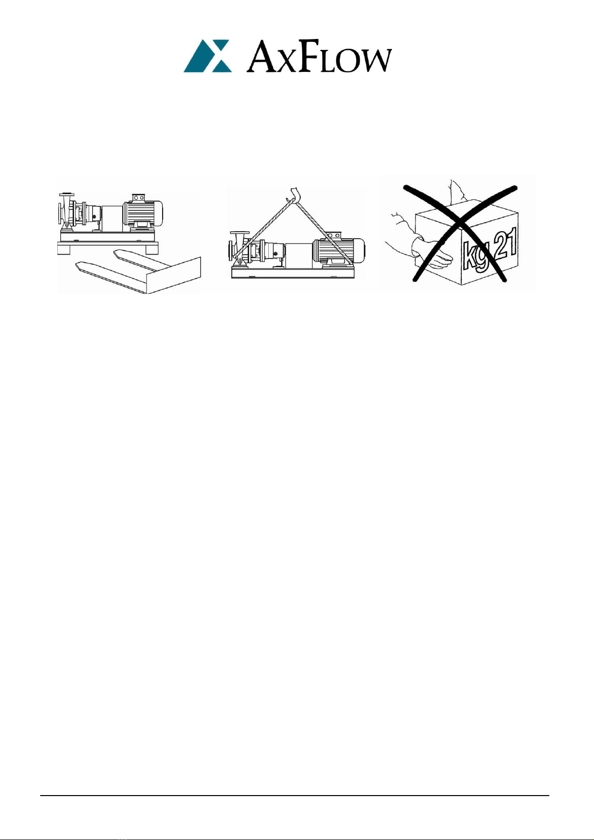
Transport ............................................................................................................................................. 3
Storage ................................................................................................................................................ 3
Drivers ..................................................................................................................................................4
INSTALLATION........................................................................................................................................ 5
Foundations ......................................................................................................................................... 5
Close-coupled motor-pump unit without baseplate ......................................................................... 5
Motor-pump units on baseplates...................................................................................................... 5
Pump and motor alignment .................................................................................................................6
Methods of checking alignment ........................................................................................................... 7
Straight edge.................................................................................................................................... 7
Dial gauge ("clocking") ..................................................................................................................... 8
Optical methods ............................................................................................................................... 8
Location and piping .............................................................................................................................. 8
Admissible external forces and torques on pump flanges .................................................................. 11
Protecting the pump against Dry Running ......................................................................................... 12
Loss of liquid supply ....................................................................................................................... 12
Low inlet pressure .......................................................................................................................... 12
`Dead-heading'............................................................................................................................... 12
Electronic dry running protection ....................................................................................................... 12
Electrical connection .......................................................................................................................... 13
Connecting the electric motor ........................................................................................................ 13
Check direction of rotation ................................................................................................................. 14
Long-coupled pumps only .............................................................................................................. 14
Direction of rotation ....................................................................................................................... 15
OPERATION .......................................................................................................................................... 16
Supervision ........................................................................................................................................ 16
Essential running precautions ............................................................................................................ 16
Priming the pump .............................................................................................................................. 19
Pump operation ................................................................................................................................. 20
MAINTENANCE ..................................................................................................................................... 22
Supply isolation .................................................................................................................................. 22
Maintenance schedule ....................................................................................................................... 22
DISASSEMBLY ....................................................................................................................................... 23
Strong magnet essential precautions ................................................................................................. 23
Decommissioning the pump .............................................................................................................. 24
Disassembling the pump .................................................................................................................... 24

CONTENTS
SVM Series Operating & Instruction Manual Page v
REASSEMBLY ........................................................................................................................................ 28
Inspection prior to reassembly ........................................................................................................... 28
Reassembling the pump ..................................................................................................................... 28
Pumping dense and/or viscous liquids ................................................................................................ 30
Reassembly of the complete pump .................................................................................................... 30
Replacing the external magnet and motor or bearing housing ........................................................... 31
Long-coupled units ......................................................................................................................... 31
Refitting the external magnet (with its bearing housing or motor) to the pump ............................ 33
Refitting the coupling (long-coupled units only) ............................................................................. 33
Typical cross-section .............................................................................................................................. 34
SVM 1 ................................................................................................................................................. 34
SVM 1.5 .............................................................................................................................................. 36
SVM 2 ................................................................................................................................................. 38
Troubleshooting..................................................................................................................................... 40
Notes .....................................................................................................................................................46

GENERAL
SVM Series Operating & Instruction Manual Page 1
GENERAL
AxFlow Aturia SVM pumps are seal less magnetically coupled sliding vane pumps. Details of the pump
type and model, serial number and operating data are indicated on the pump nameplate.
The pump must be installed and operated in full compliance with these instructions. The pump may not
be operated outside the limits specified on the nameplate and within this manual. The pump should
only be operated by skilled trained personnel. The manufacturer will not accept liability if these
instructions are not followed.
This manual does not take into account any specific local regulations or bylaws that may be applicable,
and it is the responsibility of the installer to ensure compliance with such regulations.
Noise levels
The following table reports the noise level produced by AxFlow Aturia SVM-series pumps running with
in their operating limits and installed according to the instructions given in this manual (average values
measured in free field at 1 meter from the pump set and elaborated according to ISO standard R1680 –
curve A). The values are referred to groups with AxFlow standard electric motors. For other motors the
table values shall be compared to the actual used motors.
MOTOR
FRAME SIZE
MOTOR SPEED
4 Poles 6 Poles
63 60 58
71 60 58
80 61 59
90 62 60
100 62 60

GENERAL
SVM Series Operating & Instruction Manual Page 2
Area of operation
AxFlow Aturia SVM pump sets may be installed within a building or externally. Wherever installed,
protect the pump from frost, snow and flooding.
Care must be taken to ensure that cold weather will not cause the pump or pipes to freeze, and
installers may wish to consider lagging or trace heating.
If supplied, standard electric motors are only suitable for operation in safe areas, free from the danger
of explosive liquids or gases.
Spare parts
Spare parts are available from AxFlow throughout Great Britain. Please quote the pump model and
serial number for all spares enquiries.

GENERAL
SVM Series Operating & Instruction Manual Page 3
Transport
Check the nameplate on the pump against the receiving and purchase order documents to be sure that the
correct size of pump and materials of construction have been supplied. If a motor has been supplied, check
that the power, speed, and voltage are correct.
Prior to unpacking, check for physical damage to the packing and the pump unit and notify the forwarding
agent IMMEDIATELY if any damage is found.
Check that the port covers are intact. If not, check whether foreign objects may have found their way into the
pump casing through the ports. Remove the port covers only when you are ready to connect the pipes to the
pump.
When shipped, the pumps are suitable for short-term storage only. If long-term storage is necessary
before the pump will be put into operation, we suggest that you contact your pump supplier for long-
term storage recommendations.
Check for free rotation of the pump. If the pump is close-coupled to the motor, remove the fan cover from the
motor and rotate the fan by hand. To check long-coupled pumps for free rotation, remove the coupling guard
and rotate the pump and motor shafts at the flexible coupling.
Storage
If not to be used immediately, the pumpset should be stored in a dry warm and vibration free
environment.
If an electric motor is supplied as the drive, then before putting into service, the motor winding
insulation should be tested. If the reading is below 10 Mega ohms, move to a warm dry place for a few
hours until the motor insulation value rises.
Do not remove flange covers until the pump is ready to be connected to the pipework.

GENERAL
SVM Series Operating & Instruction Manual Page 4
Drivers
AxFlow Aturia SVM pumps may be driven by an electric motor through a shaft -to-shaft coupling.
There are particular points which can affect the pump:
· Shaft -to-shaft flexible couplings must be properly aligned, as poor alignment will
cause high loads on the pump bearings. Couplings must be suitably rated, and provide
sufficient flexibility to prevent shock forces and oscillating loads from being
transmitted to the pump shaft. This is particularly important for diesel engine drives.
· When designing the drive system and prime mover, take into account that the pump
dismantles by removing the rotating element out from the back of the pump casing.
Sufficient space should be allowed to facilitate dismantling of the pump.

INSTALLATION
SVM Series Operating & Instruction Manual Page 5
INSTALLATION
Foundations
The foundation should be substantial in order to reduce vibrations, and rigid enough to prevent flexing
which can result in misalignment. Foundation bolts of the correct size should be located by reference
to certified drawings if the baseplate is supplied with the pump.
The pump must be mounted horizontally on a level foundation, with the suction / discharge ports
horizontal perpendicular to the body.
Close-coupled motor-pump unit without baseplate
Level the pump base accurately, using shims under the pump feet. The pump must sit firmly and evenly
on its foundation. It must not be distorted by bolting to an uneven surface.
Motor-pump units on baseplates
Level the baseplate accurately, using shims under the base-plate next to the foundation bolts. The
baseplate, if supplied, must sit firmly and evenly on its foundation: it must not be distorted by bolting
to an uneven surface, which will throw the pump and motor out of alignment.
Isolate the supply before
commencing work on the
pump

INSTALLATION
SVM Series Operating & Instruction Manual Page 6
CHECK THE ALIGNMENT
OF PUMP AND MOTOR
PRIOR TO START-UP
Pump and motor alignment
Close-coupled pumps have been aligned prior to shipment and if they turn freely by hand, no further
adjustments are necessary.
Long-coupled pumps have been pre-aligned with the motor prior to shipment. If pump units receive
rough treatment during shipment, they can become misaligned. The flexible coupling is not designed
to compensate for misalignment. Improper alignment will cause vibration and premature bearing
failure.

INSTALLATION
SVM Series Operating & Instruction Manual Page 7
A final alignment check should be made after the baseplate has been grouted and set, and the
foundation bolts have been tightened.
COUPLING
TYPE
OFFSET
DISPLACEMENT
ANGULARITY
GAP
Short flexible coupling
(3000 rpm) 0.05 mm 0.04 mm per 100 mm
coupling diameter
Flexible spacer coupling
(3000 rpm)
0.07 mm per
100 mm spacer length
0.04 mm per 100 mm
coupling diameter
Methods of checking alignment
Straight edge
Using a straight edge, check the distance from the shaft at several points on the circumference of the
coupling. The distances d1 and d2 should each remain constant.
IMPORTANT NOTE: The straight edge method checks static coupling alignment, not shaft alignment.
It relies for its accuracy on the accurate alignment of each coupling half on its shaft. The straight edge
method is a useful preliminary check, but should not be seen as an effective final alignment method.

INSTALLATION
SVM Series Operating & Instruction Manual Page 8
Dial gauge ("clocking")
There are several methods, using one or two dial gauges. The lost accurate is the reverse indicator
method, using two gauges, which overcomes errors due to `sag' of the gauge bars.
Optical methods
Several proprietary systems are available, such as the `OPTALIGN' system (INA Linear Systems).
Mechanical errors are eliminated by optical alignment techniques. On request, AxFlow can provide
further information about suitable alignment methods, including allowances for THERMAL
EXPANSION IN HIGH TEMPERATURE USE.
Location and piping
The correct pipework sizes should be selected according to the allowable limits of liquid velocity and
pressure drop at the required flow rate. Check the NPSH required by the pump at its specified duty
point, and ensure that the minimum NPSH available exceeds that required.
This is particularly important for liquids near their boiling temperature (or bubble point).
Check that the pipework is THOROUGHLY CLEAN before the pump is installed.
Pipework connections must be accurately aligned with the pump ports, so that they can be connected
to the pump without forcing. Maximum allowable bending moments are set out in the Table overleaf.
These moments must not be exceeded, otherwise the pump may distort internally, or the pump and
motor may become misaligned.
Pipework must be fully and independently supported as close as practicable to the pump.
Locate the pump as close as possible to the liquid source.
The suction line should be as short and straight as possible, with a minimum number of bends. Bends
should be large radius type: avoid sharp elbows. Bends and fittings should be no closer than 20 pipe
diameters to the pump suction, to allow undisturbed flow to the pump impeller. Liquid velocity in the
suction line should normally be between 0.7 and 2.0m/sec. If the liquid is near its boiling temperature
(or bubble point), its velocity may need to be reduced to 0.5-1.0m/sec. If the suction line is oversized,
the reducer at the pump inlet port should be ECCENTRIC, not concentric.
Generally, suction piping should be one or two sizes larger than the inlet bore of the pump, to keep
liquid velocity low and friction losses to a minimum. This becomes more important as the distance
between the pump and the liquid supply increases.
The suction line should slope so as to avoid air pockets.

INSTALLATION
SVM Series Operating & Instruction Manual Page 9
ATTENTION !
Valves on the suction side should be mounted with stems horizontal, or vertically downwards. All joints
in the suction line must be tight, to prevent air from entering into the system, with the risk of vapour
locking.
If the pump is installed with a negative static inlet head (lower diagram), the foot valve/ strainer must
always be immersed at a sufficient depth to avoid entry of air into the pump. Take suitable precautions
to prevent vortexing in the supply vessel. A pressure gauge should be installed in the suction line, as
close as possible to the pump.
If the supply vessel is under vacuum, a pressure balancing line should connect the supply vessel and the
pump inlet port.
The discharge line should be as short and direct as possible to minimize friction losses. An air vent (if
permissible) should be installed at the first high point in the discharge line.

INSTALLATION
SVM Series Operating & Instruction Manual Page 10
AVOID PUMPING LIQUIDS
CONTAINING
SUSPENDED SOLIDS
DO NOT PUMP LIQUIDS CONTAINING IRON OXIDES OR FERROMAGNETIC
PARTICLES, HOWEVER SMALL. THESE MAY ADHERE TO THE INTERNAL
MAGNET AND CAN EVENTUALLY BUILD UP INTO DAMAGING DEPOSITS.
A check valve and gate valve should be installed as close as possible to the pump discharge nozzle. The
check valve is installed to protect the pump from excessive back pressure or reverse flow rotation, and
to prevent back flow into the pump during shut down. The discharge (gate) valve is used to regulate the
flow. The check valve should be installed between the pump and the discharge valve to allow the pump
to be removed from service without emptying the discharge line.
A pressure gauge should be installed on the discharge side of the pump as close as possible to the
discharge nozzle.
If the pump is fitted with a STEAM HEATING JACKET, the steam must flow into the upper connection
and out of the lower connection. The heating fluid may be water with a maximum temperature of
170oC or saturated steam with a maximum pressure of 7 bar (100psi).
Prior to starting the pump it is important to flush the piping to make sure that the system is free of
solids such as pipe scale, welding beads, and dirt. If possible a TEMPORARY START-UP STRAINER with
a 40 mesh screen should be installed in the suction line.
BE VERY CAREFUL not to allow the temporary strainer to become plugged, causing low inlet pressure
with cavitation or dry running. A pressure gauge should be installed on either side of the temporary
strainer to measure the pressure drop across it. If there is any risk of ingestion of solids during normal
operation, once the pump has been successfully commissioned, a PERMANENT INLET STRAINER
should be fitted in the inlet line.
Standard AxFlow pumps are designed to handle clean liquids. Unless specifically agreed prior to
purchase of the pump from your supplier, suspended solid matter must be kept out of the pump by a
suitable inlet strainer. The strainer mesh size should be less than 0.5mm, with an open surface area at
least 2.5 x nominal cross-sectional area of pump inlet bore. The strainer must be inspected regularly
and cleaned when necessary.

INSTALLATION
SVM Series Operating & Instruction Manual Page 11
x
y
z
x
y
z
Admissible external forces and torques on pump flanges
TYPE FLANGE TORQUES, (daN) MOMENTS, (daN.m)
Fx Fy Fz ΣF Mx My Mz ΣM
SVM
1x…
Suction 150 190 125 275 50 24 40 70
Delivery 150 190 125 275 50 24 20 70
SVM
1.5x…
Suction 235 285 190 415 100 48 80 140
Delivery 235 285 190 415 100 48 80 140
SVM
2x…
Suction 310 385 250 555 140 70 110 190
Delivery 310 385 250 555 140 70 110 190

INSTALLATION
SVM Series Operating & Instruction Manual Page 12
Protecting the pump against Dry Running
The pump must not be allowed to run dry. Dry running will result in loss of liquid film to the bearings,
causing over-heating and eventual bearing failure, leading to seizure of the pump.
Avoid the following conditions:
Loss of liquid supply
Ensure that an adequate supply of liquid is available at the pump inlet at all times. Pressure and/or flow
sensors should be installed if necessary, to monitor the hydraulic conditions in the inlet pipework.
Low inlet pressure
Low inlet pressure due to restriction or blockage of the inlet pipework, causing liquid vaporization and
cavitation in the pump, with the risk of loss of liquid film in the bearings.
`Dead-heading'
If the pump is permitted to run against a closed discharge for more than a short time (depending on the
liquid, the duty, and the pump model and power), the liquid in the pump casing will heat up and
evaporate with consequences as above.
Electronic dry running protection
A rapid and reliable method of stopping a centrifugal pump, in the event of loss of liquid supply or
interruption of flow, is to monitor the power output of the motor. The `EL-FI' device monitors both
current and phase angle, providing pump protection without pipework sensors or attachments. It is
easily fitted in the power supply to the motor, in place of a normal starter. Details of power monitors
are available on request from your pump supplier.

INSTALLATION
SVM Series Operating & Instruction Manual Page 13
Electrical connection
The electrical connection to the motor should be carried out by a properly qualified electrician, using
cable, cable glands and connection procedures suitable for the electrical load and for the location of the
installation.
All regulations governing electrical installations in HAZARDOUS AREAS must be strictly followed. It is
the responsibility of the pump user to ensure that a safe electrical installation is made and maintained.
Connecting the electric motor
1. Isolate the electric supply cable from the power supply.
2. Bring the cable end into the terminal box through a suitable cable gland.
3. Follow the motor manufacturer's instructions for electrical connection. These will normally be
found inside the terminal box, either on a separate instruction sheet or attached to the inside of
the terminal box cover.
Check that the terminal links are correctly positioned for the supply voltage.
Ensure that the earth connection is properly and securely made.
Before replacing the terminal box lid, check that the sealing surfaces and the gasket or 0-ring seal are
clean and in good condition. With flameproof electric motors, the opposing metal surfaces of the
terminal box seal should be lightly greased to keep out condensation and prevent corrosion.
A proper electrical starter must be used. A starter will:
a. prevent accidental restarts after power failure
b. provide a safe, waterproof switch enclosure (IP55 `hose-protected' specification)
c. protect the motor with a correctly set thermal overload cut-out: a fuse protects only the wiring
d. withstand the heavy starting current of the motor, preventing arcing and rapid contact wear.
Isolate the supply before
commencing work on
the pump

INSTALLATION
SVM Series Operating & Instruction Manual Page 14
Check direction of rotation
Long-coupled pumps only
Prior to starting the pump the bearing housing should be filled with one of the following oils:
Use ISO VG-46 viscosity oil for bearing temperature from 0° to 70°C.
Use ISO VG-68 viscosity oil for bearing temperature 70° to 90°C.
OIL QUANTITY : BEARING BRACKET SIZE 24 0.4 lt.
Fill to the middle of the sight glass, using the following procedure:
i. pour oil into the bearing housing, through the filler cap on top of it, until oil is just visible at
the bottom of the sight glass.
ii. tip back the transparent bulb of the constant level oiler (if mounted), and fill it with oil.
iii. allow the bulb to return to its normal position. Wait for the oil to flow into the bearing
housing.
iv. repeat the operation until oil no longer flows out of the bulb.
If there is a toothed spacer coupling between the pump and the motor, check whether it needs to be
filled with oil. Follow the coupling manufacturer's instructions as required.
WARNING! “DO NOT RUN THE PUMP DRY”
This manual suits for next models
3
Table of contents
Other AxFlow Water Pump manuals
Popular Water Pump manuals by other brands

Fristam Pumps
Fristam Pumps FL2 Series Idea instruction and maintenance manual

Watson-Marlow
Watson-Marlow 501RLA user manual

Monzana
Monzana MZPP05 manual

Sundyne
Sundyne LMV-802 Installation, operation & maintenance manual

Bijur Delimon
Bijur Delimon FZ-B operating instructions

Viking pump
Viking pump 1224A-CHC Series Installation operation & maintenance

PSG Dover
PSG Dover Mouvex SLC12 i Original instructions

NorthStar
NorthStar M109163B owner's manual

GORMAN-RUPP PUMPS
GORMAN-RUPP PUMPS T10A65-B Installation, operation and maintenance manual

Tyco
Tyco Kendall Kangaroo Joey Operating and service manual

Star
Star SPCP01 manual

VERDER
VERDER VERDERAIR VA-E50 Operation