TITLE
SUB TITLE
SHEET No.
4:02
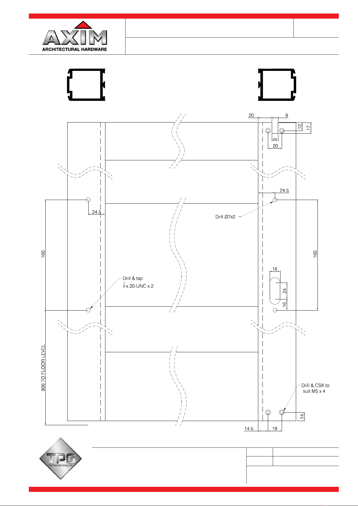
160mm
906mm
to floor
17mm 17mm
9.5mm
(.375)
Drill 5mm
(.188) and
countersink
(2)
16mm
9.5mm
(.375)
24mm
16mm
48mm
25mm
51mm
10mm
17mm
10mm
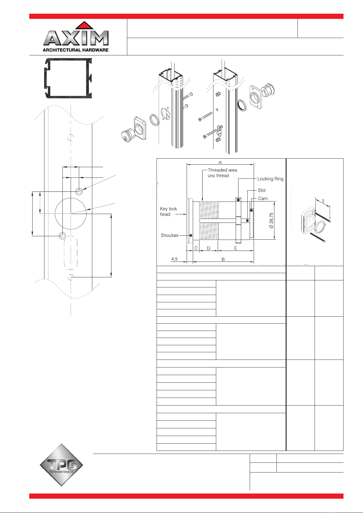
For lock cylinder only
Drill 5mm (.203)
clearance holes (2)
and 36mm
cylinder hole
Hinge stile (inside) Lock stile (inside) Lock stile (outside)
Drill 5mm
(.203) and tap
1/4-20 (2) Drill 7mm (.266)
holes (2)
Lock
cylinder
Actuator
link
Connecting
pin
160mm
25mm
25mm
25mm
47.5mm (1.875)
906mm
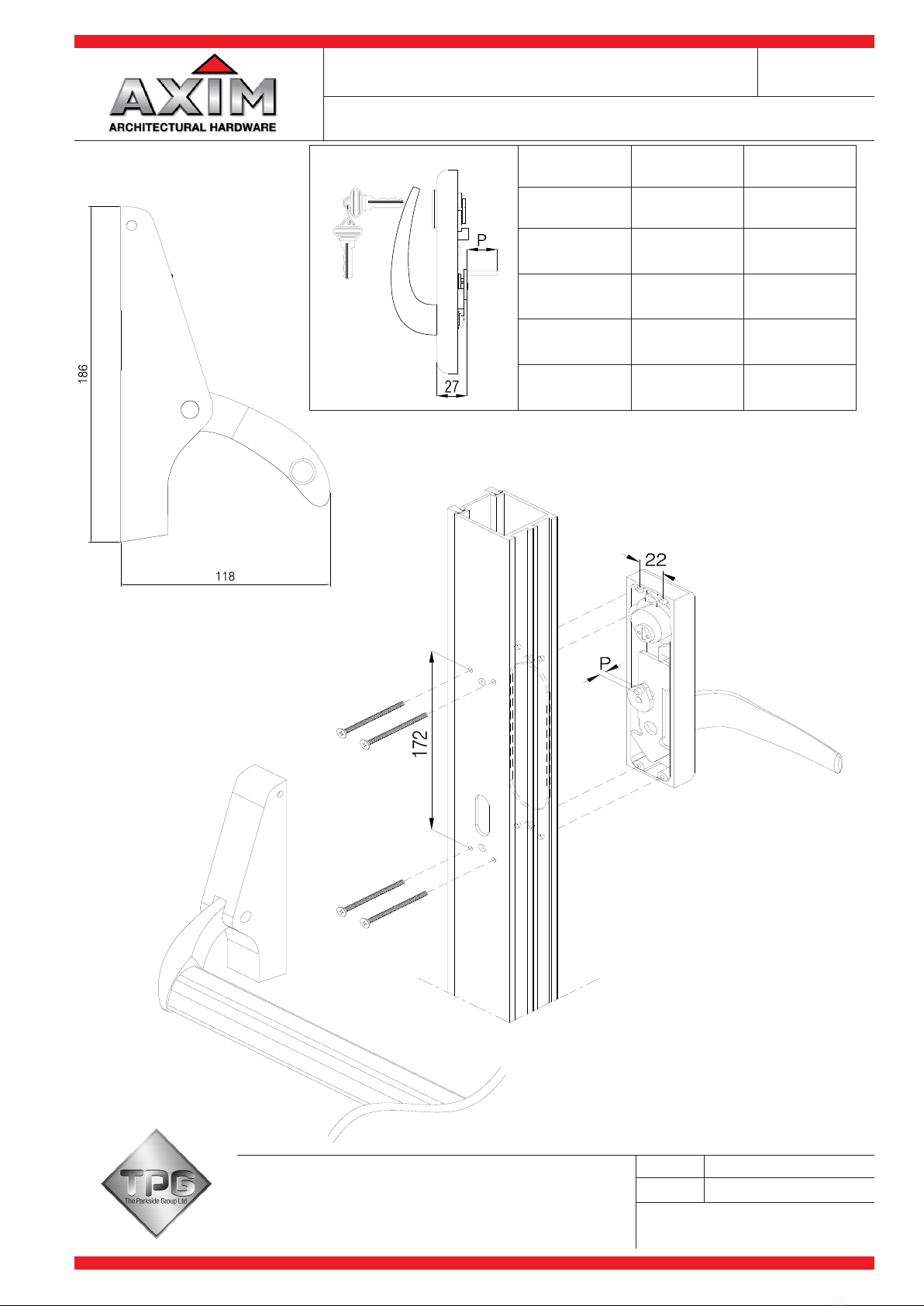
INSTALLATION OF
ACTUATOR LINK
Cross bar length (see note #8)
Dogging
pin
Actuator
pin
Place actuator link over actuator
pin & connect using connecting pin
22mm
40mm
Drill 3mm (.125) holes (4)
22mm x 27mm hole
for strike or 17mm
hole if strike not used
Strike
Adjustment screw
Trip bracket used as
release when door
stop is not used
HEADER PREPARATION
THRESHOLD PREPARATION
Strike
22mm x 27mm hole
for strike or 17mm
hole if strike not used
Drill 3mm (.125) holes (2)
17mm
9mm
12mm
Drill 5mm (.203)
& countersink (3)
See note #6
14mm
See note #6
Drill 5.2mm
(.203) and
countersink (3)
10mm
19mm
Floor line
MOUNTING INSTRUCTIONS
1. Determine hand of door and prepare inside of lock and hinge
stiles as show.
2. If Cylinder Key Lock is to be used, prepare inside and outside
of lock stile as shown.
3. Insert Rod and Case Assembly into lock stile and secure with
(2) 1/4-20 Shoulder Studs.
4. If Key Lock is used, insert Cylinder in Mounting Pad and
secure with Locking Ring. Install using (2) #8-32x49mm Flat
Head Machine Screws.
5. Position Exit Pad over stile and attach Actuator Link to Actuator
Pin using Connecting Pin provided. Place on stile over 1/4-20
Shoulder Studs and tighten 3 Socket Head Set Screws to
secure in place.
6. Adjust length of top and bottom Latch Bolts by turning in or
out. When the Panic Arm is fully depressed, the Latch Bolts
should be slightly recessed from flush with the top and bottom
of the door. NOTE: Flat notch side of Bolt must face the
outside of the door. Install top and bottom Latch Bolt Guides
using (6) #10x13mm Flat Head Self-threading Screws.
7. Install (2) 1/4-20 Shoulder Studs on hinge stile. Place other
Exit Pad over Studs and tighten 3 Socket Head Set Screws to
secure in place.
8. Measure distance from inside edge to inside edge of Exit pads
for proper Cross Bar length. Cut Cross Bar. CAUTION: Cross
Bar length must be within ± 1mm for unit to function properly.
9. Loosen 3 Set Screws on hinge stile Exit Pad and install Cross
Bar using (2) 1/4-20x25mm Oval Head Self-threading Screws.
Tighten 3 Set Screws to secure in place.
10. Prepare header and threshold as shown. If Header and
Threshold Strikes are required, install using (4) #8x25mm Flat
Head All-purpose Screws.
DOGGING EXIT DEVICE USING DOGGING PIN:
Fully depress Cross Bar and hold, push up Dogging Pin with
screwdriver and rotate 90oin either direction.
TO RELEASE EXIT DEVICE:
Hold Cross Bar down and rotate Dogging Pin with screwdriver
in either direction until Dogging Pin releases.
DOGGING EXIT DEVICE USING CYLINDER KEY:
Fully depress Cross Bar and hold, turn Key clockwise
approximately 60o, return Key to centre and remove.
TO RELEASE EXIT DEVICE:
Turn key counterclockwise 90o, return Key to centre and remove.
SCALE
DATE
For scaled technical or CAD drawings,
please contact AXIM.
NTS @A4
MARCH 2014
ASSEMBLY DETAILS PR-7085
CONCEALED ROD CRASH BAR
PR-7085 SERIES EXIT DEVICE
The Parkside Group Ltd
The Willow Centre
17 Willow Lane, Mitcham, Surrey, CR4 4NX
Tel: 020-8685 9685 Fax: 020-8646 5096
Web Site: www.axim.co.uk