manuals.online logo
Brands
  1. Home
  2. •
  3. Brands
  4. •
  5. axing
  6. •
  7. Switch
  8. •
  9. axing premium SPU 94-09 User manual

axing premium SPU 94-09 User manual

Swiss design and development
AXING AG
Gewerbehaus Moskau
CH-8262 Ramsen
[email protected]
www.axing.com
Stand 2008-04-08 - Konstruktions- und Typenänderung vorbehalten - keine Haftung für Druckfehler
State of the art 2008-04-08 - Reserving change in design and type - We cannot be held liable for printing errors
DE
EN
BETRIEBSANLEITUNG
premium
Polaritätsumschalter
-line
OPERATION INSTRUCTIONS
premium
Polarization switches
-line
Swiss design and development
Lesen und aufbewahren
Read and keep
Dieses Symbol weist darauf hin, dass das Produkt gemäß WEEE-Richtlinie
(Richtlinie über Elektro- und Elektronik-Altgeräte) (2002/96/EC) und
nationalen Gesetzen nicht über den Hausmüll entsorgt werden darf.
Dieses Produkt muss bei einer dafür vorgesehenen Sammelstelle
abgegeben werden. Dies kann z. B. durch Rückgabe beim Kauf eines
ähnlichen Produkts oder durch Abgabe bei einer autorisierten Sammelstelle
für die Wiederaufbereitung von Elektro- und Elektronik-Altgeräten
geschehen.
Informationen zu Sammelstellen für Altgeräte erhalten Sie bei Ihrer
Stadtverwaltung, dem öffentlich-rechtlichen Entsorgungsträger, einer
autorisierten Stelle für die Entsorgung von Elektro- und Elektronik-
Altgeräten oder Ihrer Müllabfuhr.
This symbol indicates that this product is not to be disposed of with your
household waste, according to the WEEE Directive (2002/96/EC) and your
national law.
This product should be handed over to a designated collection point, e.g.,
on an authorized one-for-one basis when you buy a new similar product or
to an authorized collection site for recycling waste electrical and electronic
equipment (WEEE).
For more information about where you can drop off your waste equipment
for recycling, please contact your local city office, waste authority, approved
WEEE scheme or your household waste disposal service.
WEEE Nr.
DE14023300
WEEE Nr.
DE14023300
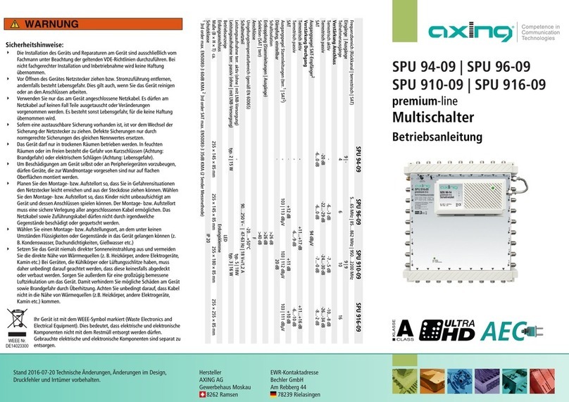
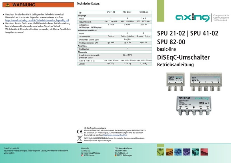
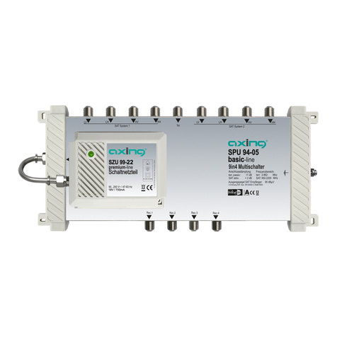
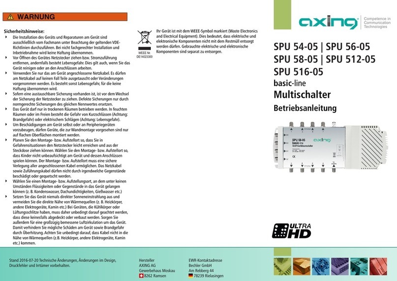
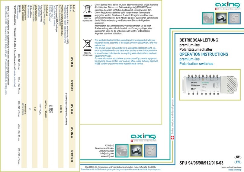
SPU 94-09
SPU 96-09
SPU 910-09
SPU 916-09
ÉSicherheitshinweise:
·
·
·
·
·
·
·
·
·
Die Installation des Geräts und Reparaturen am Gerät sind ausschließlich vom Fachmann unter
Beachtung der geltenden VDE-Richtlinien durchzuführen. Bei nicht fachgerechter Installation und
Inbetriebnahme wird keine Haftung übernommen.
Vor Öffnen des Gerätes Netzstecker ziehen bzw. Stromzuführung entfernen, andernfalls besteht
Lebensgefahr. Dies gilt auch, wenn Sie das Gerät reinigen oder an den Anschlüssen arbeiten.
Verwenden Sie nur das am Gerät angeschlossene Netzkabel. Es dürfen am Netzkabel auf keinen Fall
Teile ausgetauscht oder Veränderungen vorgenommen werden. Es besteht sonst Lebensgefahr, für die
keine Haftung übernommen wird.
Sofern eine austauschbare Sicherung vorhanden ist, ist vor dem Wechsel der Sicherung der
Netzstecker zu ziehen. Defekte Sicherungen nur durch normgerechte Sicherungen des gleichen
Nennwertes ersetzen.
Das Gerät darf nur in trockenen Räumen betrieben werden. In feuchten Räumen oder im Freien
besteht die Gefahr von Kurzschlüssen (Achtung: Brandgefahr) oder elektrischem Schlägen (Achtung:
Lebensgefahr).
Planen Sie den Montage- bzw. Aufstellort so, dass Sie in Gefahrensituationen den Netzstecker leicht
erreichen und aus der Steckdose ziehen können. Wählen Sie den Montage- bzw. Aufstellort so, dass
Kinder nicht unbeaufsichtigt am Gerät und dessen Anschlüssen spielen können. Der Montage- bzw.
Aufstellort muss eine sichere Verlegung aller angeschlossenen Kabel ermöglichen. Das Netzkabel
sowie Zuführungskabel dürfen nicht durch irgendwelche Gegenstände beschädigt oder gequetscht
werden.
Um Beschädigungen am Gerät selbst oder an Peripheriegeräten vorzubeugen, dürfen Geräte, die zur
Wandmontage vorgesehen sind nur auf flachen Oberflächen montiert werden.
Wählen Sie einen Montage- bzw. Aufstellungsort, an dem unter keinen Umständen Flüssigkeiten oder
Gegenstände in das Gerät gelangen können (z. B. Kondenswasser, Dachundichtigkeiten, Gießwasser
etc.)
Setzen Sie das Gerät niemals direkter Sonneneinstrahlung aus und vermeiden Sie die direkte Nähe
von Wärrmequellen (z. B. Heizkörper, andere Elektrogeräte, Kamin etc.) Bei Geräten, die Kühlkörper
oder Lüftungsschlitze haben, muss daher unbedingt darauf geachtet werden, dass diese keinesfalls
abgedeckt oder verbaut werden. Sorgen Sie außerdem für eine großzügig bemessene Luftzirkulation
um das Gerät. Damit verhindern Sie mögliche Schäden am Gerät sowie Brandgefahr durch
Überhitzung. Achten Sie unbedingt darauf, dass Kabel nicht in die Nähe von Wärmequellen (z.B.
Heizkörper, andere Elektrogeräte, Kamin etc.) kommen.
ÉSafety advice:
·
·
·
·
·
·
·
·
·
Installation and repairs to the equipment may only be carried out by technicians observing the current
VDE guidelines. No liability will be assumed in the case of faulty installation and commissioning.
Before opening the equipment pull out the power plug or remove the power supply, otherwise there is
danger of electrocution. This is also valid for cleaning the equipment or working on the connections.
Providing that a serviceable fuse exists, the power plug must be pulled out before changing the fuse.
Defective fuses may only be replaced with standard compliant fuses that have the same nominal
value.
The equipment may only be operated in dry rooms. In humid rooms or outdoors there is danger of
short-circuit (caution: risk of fire) or electrocution.
Choose the location of installation or mounting so that the power plug can be reached and pulled out of
the socket easily in case of danger. Choose the location of installation or mounting such that children
may not play unsupervised near the equipment and its connections. The location of installation or
mounting must allow a safe installation of all cables connected. The mains cable as well as feeder lines
may not be damaged or clamped by objects of any kind.
To prevent damage to your equipment and to avoid possible peripheral damages, the devices foreseen
for wall mounting may only be installed on a flat surface.
Choose the location of installation or mounting so that under no circumstances liquids or objects can
get into the equipment (e.g. condensation, water coming from leaking roofs or flowing water, etc.).
Avoid exposure of the equipment to direct sunlight and to other heat sources (e. g. radiators. other
electrical devices, chimney, etc.). Devices that are equipped with heat sinks or ventilation slots must
under no circum-stances be covered or blocked. Also ensure for a generous air circulation around the
equipment. In this way you avoid possible damage to the equipment as well as a risk of fire caused by
overheating. Absolutely avoid that cables come near any source of heat (e.g. radioators, other
electrical devices, chimney, etc.).
Only use the mains cable connected to the device. Never replace any parts or make any modifications
on the mains cable. Otherwise there is a risk of mortal injury for which we cannot be held liable.
Stand 11.10.07 - Konstruktions- und Typenänderung vorbehalten - keine Haftung für ruckfehler
State of the art 11.10.07 - Reserving change in design and type - We cannot be held liable for printing errors
Artikel
Article SPU 94-09 SPU 96-09 SPU 910-09 SPU 916-09
Frequenzbereich (Rückkanal/terrestrisch/SAT)
Frequency range (return path/terrestrial/SAT) 5...65 MHz/85...862 MHz/950...2200 MHz
Anschlussdämpfung
Tap loss
terrestrisch aktiv
terrestrial active - 6...3 dB 7...5 dB 10...8 dB
terrestrisch passiv
terrestrial passive 20 dB 22...29 dB 24...30 dB 26...34 dB
SAT
SAT 6...0 dB 6...0 dB 7...0 dB 8...2 dB
Ausgangspegel SAT-Empfänger
2
Output level SAT receiver
2
94 dBµV
urchgang
Trunk
terrestrisch aktiv (Verstärkung)
terrestrial active (gain) -11...17 dB 11...16 dB
terrestrisch passiv ( ämpfung)
terrestrial passive (loss) - 6...9 dB 6...10 dB
SAT (Verstärkung)
SAT (gain) -9...15 dB 9...12 dB 9...10 dB
Ausgangspegel Stammleitungen (terr.
1
/SAT
2
)
Output level trunk (terr.
1
/SAT
2
)- 103/113 dBµV 103/112 dBµV 103/111 dBµV
1
3rd order max. EN50083-3 60dB KMA
2
3rd order SAT max. EN50083-3 35dB KMA (2 Sender Messmethode/2 sender test method)
Verwendungsbereich:
Die Geräte sind ausschließlich für den Einsatz zum Verstärken sowie Verteilen
von Radio- und Fernsehsignalen im Haus geeignet! Wird ein Gerät für andere
Einsätze verwendet, wird keine Garantie übernommen!
Die Abbildung zeigt ein Anwendungsbeispiel für die Verteilung von 8 SAT-ZF-
Polarisationsebenen inklusive terrestrischer Signale (z.B. UKW-Radio)
Field of application:
The picture shows an application example for distribution of 8 SAT IF
polarization levels including terrestrial signals (e.g. FM radio).
The devices are only suitable for in-house distribution of RF signals. If a device
is used for other purposes, no warranty is given!
HF-Anschluss:
!
!
!
!
Verbinden Sie die SAT-Eingänge des Polaritätsumschalters mit den LNBs Ihrer
SAT-Empfangsantenne. Speisen Sie in den terr. Eingang Ausgangssignale
eines terrestrischen Verstärkers bzw. eines BK-Hausanschlussverstärkers ein.
Verbinden Sie die seitlichen Ausgänge des mit den
Antennensteckdosen.
Polaritätsumschalters
Verwenden Sie hierfür hochgeschirmte Koaxialkabel mit
F- Anschlusssteckern. Passende Kabel und Stecker finden Sie im aktuellen
AXING-Katalog oder unter www.axing.com.
Wenn Sie keine Kaskadebausteine am Polaritätsumschalter anschließen, dann
schließen Sie die unteren Ausgänge mit den beiliegenden
Abschlusswiderständen CFA 11-00 ab.
Wenn Sie Kaskadebausteine am Polaritätsumschalter anschließen, verbinden
Sie diese mit F/F-Quickfix-Adaptern CFA 4-01.
RF-Installation:
!
!
If you don´t use cascade units to expand the poarization switch, t
If you use cascade units to expand the poarization switch, connect them with
F/F Quickfix adapters CFA 4-01.
!
!
Connect the SAT inputs of the polarization switch to the LNBs of your SAT
reception antenna. Connect the output signals of a terrestrial amplifier or a
CATV amplifier to the terrestrial input.
Connect the outputs on the left and right sides of the polarization switch to the
antenna sockets. Use highly shielded coaxial cables with F connectors.
Suitable cables and connectors can be found in the current AXING catalogue or
under www.axing.com.
erminate the
outputs on the lower side with the resistors CFA 11-00 enclosed.
Kaskadierung :(nur SPU 96-09, SPU 910-09 und SPU 916-09)
Die Polaritätsumschalter SPU 96-09, SPU 910-09 und SPU 916-09 können mit
den Kaskadebausteinen SPU 996-09, SPU 998-09, SPU 9912-09 und
SPU 9918-09 erweitert werden.
Beachten Sie bei der Inbetriebnahme dieser Kaskadebausteine deren
Betriebsanleitungen.
Verbinden Sie die Ausgänge der Polaritätsumschalter mit den Eingängen der
Kaskadebausteine. Verwenden Sie dazu F/F-Quickfix-Adapter CFA 4-01
(nicht im Lieferumfang enthalten).
Schließen Sie die Ausgänge des letzten Kaskadebausteins mit den
beiliegenden Abschlusswiderständen CFA 11-00 ab.
!
!
!
Cascading :(SPU 96-09, SPU 910-09 and SPU 916-09 only)
The polarization switches SPU 96-09, SPU 910-09 and
I
Connect the outputs of the polarization switches with the inputs of the
cascade units. Use F/F Quickfix adapters CFA 4-01 (not included in delivery).
!
!
!
SPU 916-09 can be
extended with the cascade units SPU 996-09, SPU 998-09, SPU 9912-09 und
SPU 9918-09.
Please note when installing these cascade units the appropriate operation
instructions.
Terminate the outputs of the last cascade units with the resistors CFA 11-00
enclosed.
Absetzen des Netzteils:
Wenn sich in der Nähe der Multischalters keine Netzsteckdose befindet, kann
das Netzteil des Polaritästumschalters abgesetzt und der Polaritätsumschalter
über ein entsprechend langes Koaxkabel versorgt werden (max. 10 m lang).
!
!
!
!
Lösen Sie das Netzteil vom Polaritätsumschalter ab. Drücken Sie dazu die
Verrieglungsnase der Grundplatte nach unten und schieben Sie das Netzteil
nach rechts aus seiner Halterung.
Befestigen Sie das Netzteil an einer Stelle, an der sich eine Netztsteckdose
befindet. Verwenden Sie die dem Gerät beiliegenden Montageschrauben und
die Montagelöcher links oben bzw. rechts unten am Netzteil.
Verbinden Sie den DC-Ausgang des Netzteils (F-Buchse) mit dem DC-
Eingang des Polaritätsumschalters. Verwenden Sie dazu ein Koaxialkabel mit
F- Anschlusssteckern.
Schließen Sie das Netzteil erst dann an der Netzsteckdose an, wenn alle
Installationsarbeiten abgeschlossen sind.
Remove of the power supply
Remove the power supply by pressing down the little nose of the base plate
and push the power supply to the right side; then you can take it off.
Fix the power supply close to a power socket. Use the included screws and fix
the power supply at the foreseen mounting holes (top left and bottom right )
Connect the DC-output of the power supply (F-female connector ) with the
DC-input of the multiswitch. Use an appropriate coaxial cable with F-
connectors.
Connect the power supply only to mains when all installation works are
finished
When there is no mains close to the multi-switch, the power supply can be
removed and connected with an appropriate coaxial cable (max. length 10 m).
!
!
!
!
terr. Eingang
terr. input
Überspannungsschutz:
Empfehlung: Verwenden Sie Überspannungsschutz-Geräte (wie z. B. AXING
SZU 6-02), um Ihre Polarisationsumschalter vor Schäden durch Überspannung
zu schützen.
Overvoltage protection:
Recommandation: Use overvoltage protection devices (like e. g. AXING SZU
6-02) to protect your polarization switches against overvoltage.
Erdung, Montage und Spannungsversorgung:
!Zur Vermeidung gefährlicher Überspannungen (Achtung: Brand-
/Lebensgefahr), müssen die Geräte geerdet werden. Verwenden Sie die am
Gerät angebrachte Erdungsklemme .
Verwenden Sie die dem Gerät beiliegenden Montageschrauben und die
Montagelöcher am Gerät .
1
2
!
!Das beiliegende 15 cm lange F-Anschlusskabel dient dem Anschluss
des abnehmbaren Schaltnetzteils an den Multischalter.
3
Grounding, Mounting and Power supply:
!
!
Use the included mounting screws and the mounting holes of the device .
The enclosed 15 cm long F-connecting cable is used to combine the
detachable switching mode power supply to the multiswitch.
2
3
!To avoid dangerous power surges (e.g. risk of fire and danger of life) all
devices must be grounded. Use the screw terminal at the device .1
Ausgänge zu Kaskadebausteinen
Outputs to cascade units
SAT-Eingänge/SAT inputs
Ausgänge zu
SAT-Receivern
Outputs to
SAT receivers
CFA 11-00
Netzteil
Power supply
CFA 4-01
1
2
4
3
5
6
2
Pegeleinstellungen :(nur SPU 96-09, SPU 910-09 und SPU 916-09)
Der terrestrische Eingang des Polaritätsumschalter ist regelbar . Wenn
notwendig, kann der terrestrische Zweig passiv geschaltet werden .
4
5
Level Adjustment :(SPU 96-09, SPU 910-09 and SPU 916-09 only)
The terrestrial input of our polarization switch can be adjusted . If necessary,
the terrestrial path can be switched passiv .
4
5
9 × SZU 6-02
Multifunktions LED:
Der Polaritätsumschalter verfügt über eine Multifunktions-LED , die mit
verschiedenen Farben unterschiedliche Betriebszustände anzeigt.
6
!
!
!
grün = Betrieb
gelb = Stand by (kein Receiver angeschlossen oder eingeschaltet)
rot = LNB-Kurzschluss, überprüfen Sie die Verkabelung der LNB
Multifunction LED:
The polarization switch comes with a multifunction LED , which shows
different operation modes with different colours.
6
!
!
!
green = in operation
yellow = stand by (no receiver connected respc. on)
red = LNB short-circuit (check the cabling and rectify the error)

This manual suits for next models

3

Other axing Switch manuals

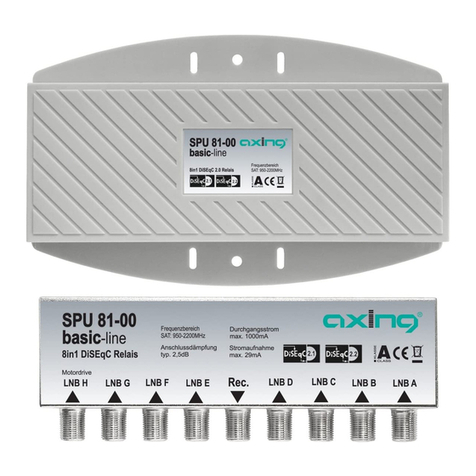
axing basic-line SPU 81-00 User manual

axing

axing basic-line SPU 81-00 User manual

axing premium-line SES 5216-06 User manual

axing

axing premium-line SES 5216-06 User manual

axing premium-line Series User manual

axing

axing premium-line Series User manual

axing premium-line SPU 996-09 User manual

axing

axing premium-line SPU 996-09 User manual

axing basic-line SPU 94-05 User manual

axing

axing basic-line SPU 94-05 User manual

axing Premium Series User manual

axing

axing Premium Series User manual

axing SPU 21-02 User manual

axing

axing SPU 21-02 User manual

axing basic-line Series User manual

axing

axing basic-line Series User manual

axing premium SES 5216-06 User manual

axing

axing premium SES 5216-06 User manual

axing basic-line SPU 58-06 User manual

axing

axing basic-line SPU 58-06 User manual

axing Premium SES 5532-19 User manual

axing

axing Premium SES 5532-19 User manual

axing premium-line SES 522-06 User manual

axing

axing premium-line SES 522-06 User manual

axing premium-line SPU 94-03 User manual

axing

axing premium-line SPU 94-03 User manual

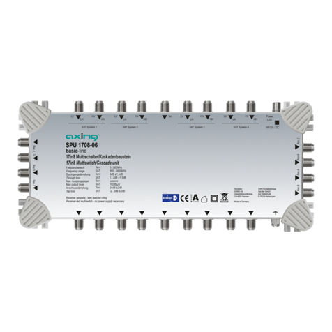
axing SPU 98-06 User manual

axing

axing SPU 98-06 User manual

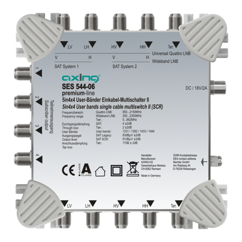
axing premium SES 544-06 User manual

axing

axing premium SES 544-06 User manual

axing premium-line Series User manual

axing

axing premium-line Series User manual

axing SPU 48-01 User manual

axing

axing SPU 48-01 User manual

axing basic-line SPU 21-01 User manual

axing

axing basic-line SPU 21-01 User manual

axing SPU 56-05 User manual

axing

axing SPU 56-05 User manual

axing SPU 1708-06 User manual

axing

axing SPU 1708-06 User manual

axing SES 984-06 User manual

axing

axing SES 984-06 User manual

axing premium-line SPU 556-09 User manual

axing

axing premium-line SPU 556-09 User manual

axing basic SPU 54-05 User manual

axing

axing basic SPU 54-05 User manual

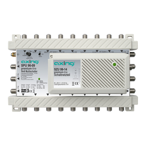
axing premium-line SPU 94-09 User manual

axing

axing premium-line SPU 94-09 User manual

Popular Switch manuals by other brands

AMX Triple Switch Module 20A RDM-3SWM Installation sheet

AMX

AMX Triple Switch Module 20A RDM-3SWM Installation sheet

D-Link DGS-3000-52X Quick installation guide

D-Link

D-Link DGS-3000-52X Quick installation guide

Linear LTC7860 Demo Manual

Linear

Linear LTC7860 Demo Manual

Comnet CNGE2FE24MSPOE Installation and operation manual

Comnet

Comnet CNGE2FE24MSPOE Installation and operation manual

Targus USB-2.0 Mobile Mini Hub user guide

Targus

Targus USB-2.0 Mobile Mini Hub user guide

TP-Link TL-SF1016DS installation guide

TP-Link

TP-Link TL-SF1016DS installation guide

socomec 97232010 quick start

socomec

socomec 97232010 quick start

socomec ATyS UL 1008 instruction manual

socomec

socomec ATyS UL 1008 instruction manual

EtherWAN TG103H installation guide

EtherWAN

EtherWAN TG103H installation guide

Entone Amulet 500 Series quick start guide

Entone

Entone Amulet 500 Series quick start guide

Ruijie RG-S29 Series Command reference manual

Ruijie

Ruijie RG-S29 Series Command reference manual

Cisco Catalyst 3850 Deployment guide

Cisco

Cisco Catalyst 3850 Deployment guide

StarTech.com VS421HD4KA Quick install guide

StarTech.com

StarTech.com VS421HD4KA Quick install guide

Cisco Catalyst 4500 Series overview

Cisco

Cisco Catalyst 4500 Series overview

Lindy IPower Control 2x6 user guide

Lindy

Lindy IPower Control 2x6 user guide

Cisco Catalyst 4000 series Hardware troubleshoot

Cisco

Cisco Catalyst 4000 series Hardware troubleshoot

Steren USB-524 instruction manual

Steren

Steren USB-524 instruction manual

Digitus DN-651154 Quick installation guide

Digitus

Digitus DN-651154 Quick installation guide

manuals.online logo
manuals.online logoBrands
  • About & Mission
  • Contact us
  • Privacy Policy
  • Terms and Conditions

Copyright 2025 Manuals.Online. All Rights Reserved.