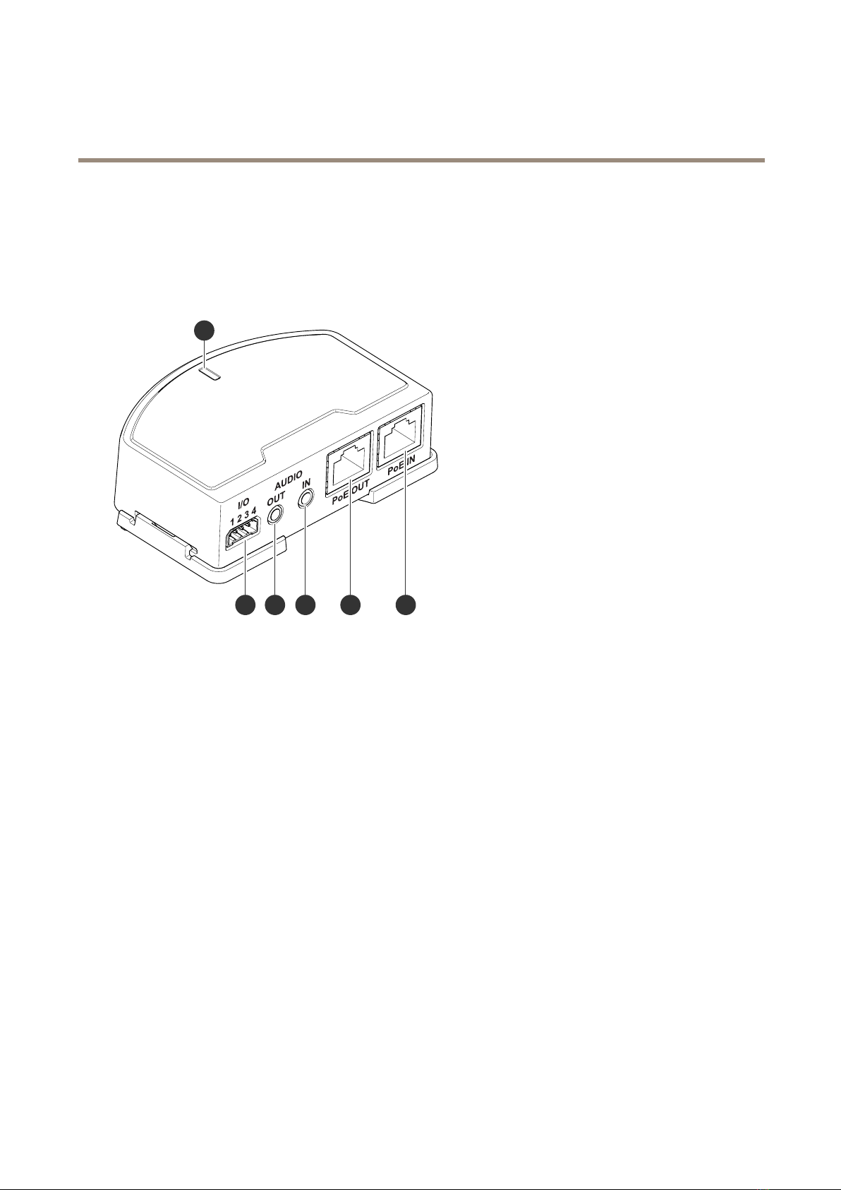
AXIST61MkIIAudioandI/OInterfaceSeries
Configureyourdeice
5.SelecttheConditionthatmustbemettotriggerthecameratostartrecording.Itcan,forexample,beatimescheduleor
motiondetection.
6.Inthelistofactions,selectRecordvideo.Selectastoragespace.Selectastreamproleorcreateanew.Alsosetthe
PrebufferandPostbufferasrequired.
7.Savetherule.
8.CreateasecondruleandselectthesameConditionasintherstrule.
9.Inthelistofactions,selectToggleI/Ohiletheruleisactive,andthenselecttheporttheAXISI/OIndicationLEDis
connectedto.SetthestatetoActive.
0.Savetherule.
OtherscenarioswhereAXISI/OIndicationLEDcanbeusedareforexample:
•ConguretheLEDtoturnonwhenthecamerastarts,toindicatethepresenceofthecamera.SelectSystemreadyas
acondition.
•ConguretheLEDtoturnonwhenlivestreamisactivetoindicatethatapersonoraprogramisaccessingastreamfrom
thecamera.SelectLivestreamaccessedasacondition.
Openthelocktoaatewhensomeoneisnearby
Thisexampleexplainshowtodirectthecameraandopenagatewhensomeonewantstoenterduringdaytime.Thisisdoneby
connectingaPIRdetectortotheproduct’sinputportandaswitchrelaytotheproduct’soutputport.
Requiredhardare
•MountedPIRdetector
•Switchrelayconnectedtothegatelock,inthiscasetheswitchisnormallyclosed(NC)
•Connectingwires
Physicalconnection
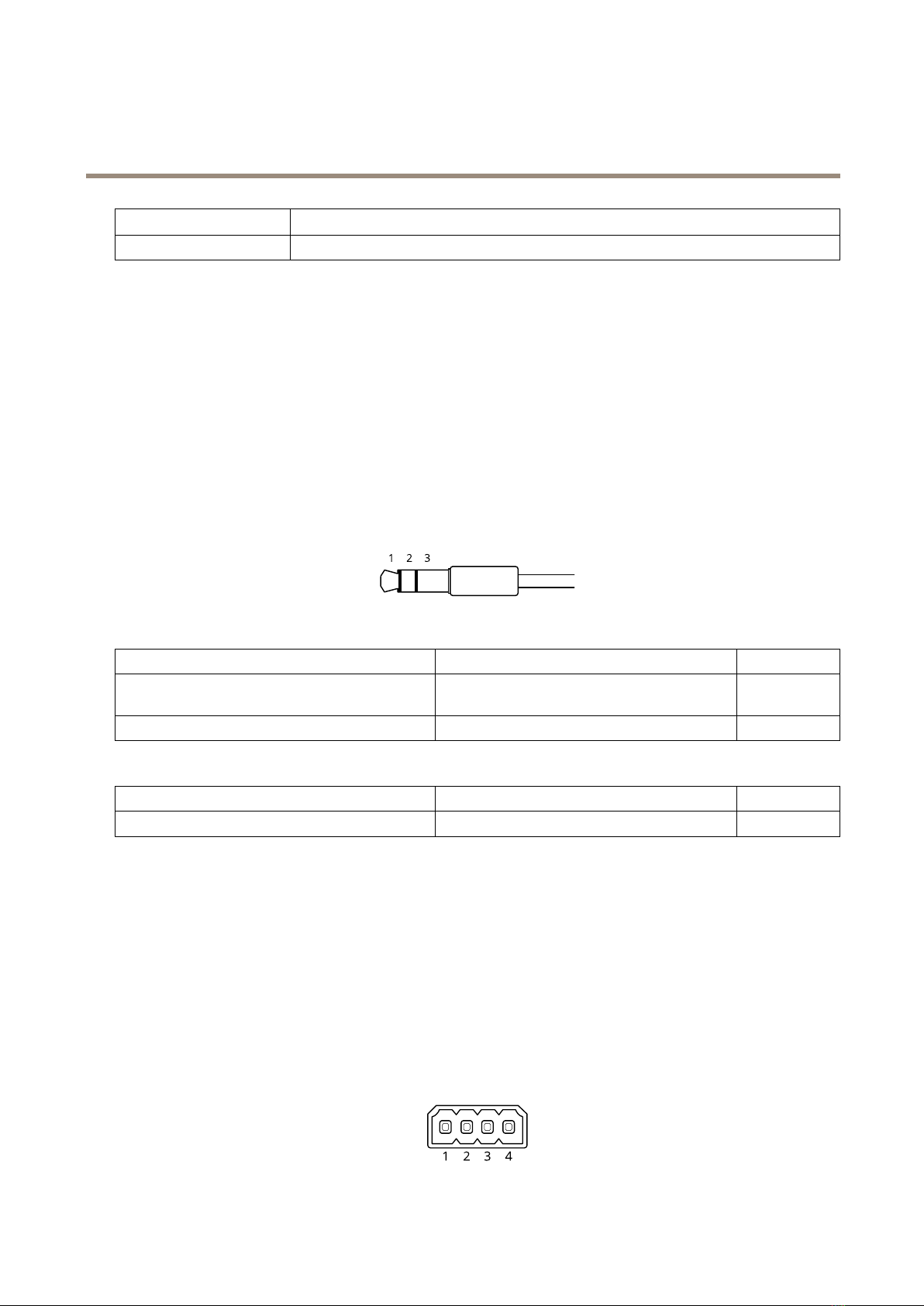
.ConnectthewiresfromthePIRdetectortotheinputpin,seeI/Oconnectoronpage1.
2.Connectthewiresfromtheswitchtotheoutputpin,seeI/Oconnectoronpage1
ConureI/Oports
Youneedtoconnecttheswitchrelaytothecamerafromthecamera’swebpage.First,conguretheI/Oports:
SetthePIRdetectortoaninputport
.GotoSystem>Accessories>I/Oports.
2.Clicktosetthedirectiontoinputforport.
3.Givetheinputmoduleadescriptivename,forexample“PIRdetector”.
4.IfyouwanttotriggeraneventwheneverthePIRdetectorsensesmotion,clicktosetthenormalstatetocircuitopen.
Setthesitchrelaytoanoutputport
.Clicktosetthedirectiontooutputforport2.
2.Givetheoutputmoduleadescriptivename,forexample“Gateswitch”.
5