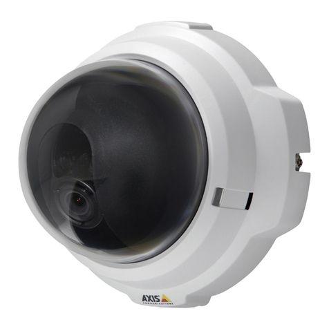
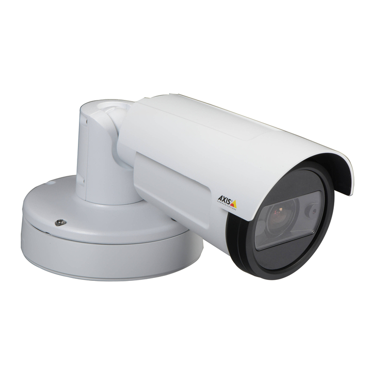
Axis T90C User manual

ENGLISH DEUTSCH ITALIANO ESPAÑOL
INSTALLATION GUIDE
FRAN
Ç
AIS
AXIS T90C10 Fixed Dome IR-LED
AXIS T90C20 Fixed Dome IR-LED

Legal Considerations
Video and audio surveillance can be prohibited by laws that
vary from country to country. Check the laws in your local
region before using this product for surveillance purposes.
Electromagnetic Compatibility (EMC)
This equipment has been designed and tested to fulfill
applicable standards for:
• Radio frequency emission when installed according to the
instructions and used in its intended environment.
• Immunity to electrical and electromagnetic phenomena
when installed according to the instructions and used in
its intended environment.
USA - This equipment has been tested using a shielded
network cable (STP) and found to comply with the limits for
a Class B digital device, pursuant to part 15 of the FCC
Rules. These limits are designed to provide reasonable
protection against harmful interference in a residential
installation. This equipment generates, uses and can radiate
radio frequency energy and, if not installed and used in
accordance with the instructions, may cause harmful
interference to radio communications. However, there is no
guarantee that interference will not occur in a particular
installation. If this equipment does cause harmful
interference to radio or television reception, which can be
determined by turning the equipment off and on, the user is
encouraged to try to correct the interference by one or more
of the following measures:
• Reorient or relocate the receiving antenna.
• Increase the separation between the equipment and
receiver.
• Connect the equipment into an outlet on a circuit
different from that to which the receiver is connected.
• Consult the dealer or an experienced radio/TV technician
for help.
Europe - This digital equipment fulfills the
requirements for RF emission according to the Class B limit
of EN 55022.
This product fulfills the requirements for immunity
according to EN 55024 office and commercial
environments.
Canada - This Class B digital apparatus complies with
Canadian ICES-003.
Australia - This digital equipment fulfills the
requirements for RF emission according to the Class B limit
of AS/NZS CISPR 22.
Japan - この装置は、クラスB 情報技術装置です。
この装置は、家庭環境で使用することを目 的として
いますが、この装置がラジオやテレビジョン受信機
に近接して使用されると、 受信障害を引き起こすこ
とがあります。 取扱説明書に従って正しい取り扱い
をして下さい。
Korea -
ࢇЕɼࢽࡈ%ࢷળࢶଢԻ۰
࣯Իɼࢽ߾۰یࡈଜЕʨࡶּࢶࡳԻଜֲֻҘ
ࠇ߾۰یࡈଟܹݡТЬ
Safety
This product complies to EN/IEC 60950-1 and EN/IEC
60950-22, Safety of Information Technology Equipment.
The power supply used with this product shall fulfill the
requirements for Safety Extra Low Voltage and Limited
Power Source according to EN/IEC/UL 60950-1.
Equipment Modifications
This equipment must be installed and used in strict
accordance with the instructions given in the user
documentation. This equipment contains no
user-serviceable components. Unauthorized equipment
changes or modifications will invalidate all applicable
regulatory certifications and approvals.
Liability
Every care has been taken in the preparation of this
document. Please inform your local Axis office of any
inaccuracies or omissions. Axis Communications AB cannot
be held responsible for any technical or typographical errors
and reserves the right to make changes to the product and
documentation without prior notice. Axis Communications
AB makes no warranty of any kind with regard to the
material contained within this document, including, but not
limited to, the implied warranties of merchantability and
fitness for a particular purpose. Axis Communications AB
shall not be liable nor responsible for incidental or
consequential damages in connection with the furnishing,
performance or use of this material. This product is only to
be used for its intended purpose.
RoHS
This product complies with both the European RoHS
directive, 2002/95/EC, and the Chinese RoHS
regulations, ACPEIP.
WEEE Directive
The European Union has enacted a Directive
2002/96/EC on Waste Electrical and Electronic
Equipment (WEEE Directive). This directive is
applicable in the European Union member states.
The WEEE marking on this product (see right) or its
documentation indicates that the product must not be
disposed of together with household waste. To prevent
possible harm to human health and/or the environment, the
product must be disposed of in an approved and
environmentally safe recycling process. For further
information on how to dispose of this product correctly,
contact the product supplier, or the local authority
responsible for waste disposal in your area.
Business users should contact the product supplier for
information on how to dispose of this product correctly. This
product should not be mixed with other commercial waste.
Support
Should you require any technical assistance, please contact
your Axis reseller. If your questions cannot be answered
immediately, your reseller will forward your queries through
the appropriate channels to ensure a rapid response. If you
are connected to the Internet, you can:
• download user documentation and firmware updates
• find answers to resolved problems in the FAQ database.
Search by product, category, or phrases
• report problems to Axis support by logging in to your
private support area
• chat with Axis support staff (selected countries only)
• visit Axis Support at www.axis.com/techsup/
ENGLISH
Safeguards
Please read through this Installation Guide carefully before installing the Axis product. Keep the
Installation Guide for further reference.
• Store the Axis product in a dry and ventilated environment.
• Avoid exposing the Axis product to vibration, shocks or heavy pressure. Do not install the
product on unstable brackets, unstable or vibrating surfaces or walls, since this could cause
damage to the product.
• Only use applicable tools when installing the Axis product; excessive force could cause
damage to the product.
• Do not use chemicals, caustic agents, or aerosol cleaners. Use a damp cloth for cleaning.
• Use only accessories that comply with technical specification of the product. These can be
provided by Axis or a third party.
• Use only spare parts provided by or recommended by Axis.
• Do not attempt to repair the product by yourself, contact Axis or your Axis reseller for ser-
vice matters.
• This Axis product shall be used in compliance with local laws and regulations.
• To use this Axis product outdoors, it shall be installed in an approved outdoor housing.
• The Axis product should be installed by a trained professional. Observe relevant national
and local regulations for the installation.
Transportation
• When transporting the Axis product, use the original packaging or equivalent to prevent
damage to the product.


AXIS T90C10/T90C20 Installation Guide Page 5
ENGLISH
AXIS T90C10/T90C20 Fixed Dome IR-LED
Installation Guide
This guide provides instructions for installing the AXIS T90C10/ AXIS T90C20 IR-LED with the
following fixed dome cameras:
• AXIS P3343-VE
• AXIS P3344-VE
• AXIS P3346-VE
To install the camera, refer to the installation guide supplied with the product.
The contents of this guide are as follows:
1. Package Contents. See below.
2. Installation, on page 8.
3. Specifications, on page 12.
Package Contents
Item Models/variants/notes
Lighting Module PoE Cat 5 cable
(for AXIS T90C20 Fixed Dome IR-LED)
18-56V DC Power Control cable
(for AXIS T90C10 IR-LED)
Printed materials AXIS T90C10/T90C20 Fixed Dome IR-LED Installation Guide
(this document)

Page 6 AXIS T90C10/T90C20 Installation Guide
Hardware Overview
AXIS P33 Fixed Dome camera
Photocell
IR-LED
PoE Cat 5 or 18-56 V DC Power
(pre-mounted)
5-meter cable
Specifications subject to change without notice. Installation to be carried out by trained and qualified personnel.

AXIS T90C10/T90C20 Installation Guide Page 7
ENGLISH
Recommendations
This Axis product is delivered with the LED block facing the front and this positioning is appropriate
for most installations; it is however possible to move the LED block to face other directions. See
page 10.
Note: Use screws appropriate for your wall material.
20-30m
Max illumination
Less illumination Less illumination
120˚

Page 8 AXIS T90C10/T90C20 Installation Guide
Installation
Notes:
• When the IR-LED is installed, the camera cables can only be routed through the wall (not along the wall).
•The
IR-LED is controlled by the level of ambient light which is detected by the unit's photocell. Ensure that
the photocell is not obstructed or covered.
1. If the camera is already installed, disconnect power from the camera; remove the weather
shield, and the dome cover on the camera; remove the unit casing from the mounting bracket;
detach the camera unit.
If the camera is not already installed, attach the mounting bracket to the wall. Please check the
camera’s installation guide for this and further installation procedures.
2. Remove the side lid from the unit casing; save the screw.
If the camera lens is to face right or left, please read the information on page 10 before you
proceed.
3. Remove the gasket from one of the side holes and
from the corresponding back hole in the unit casing,
for cabling. (The cable for the IR-LED should enter
the hole to the left in the unit casing)
Route the IR-LED cable through the side hole and
through the back hole in the unit casing.
4. Force the 2 gaskets on the cable through the side
hole.
Mounting bracket
Unit casing
Dome cover
Weather shield
Side holes
Back hole
Back hole
Side lid
Screw
Unit casing
Gaskets in side
and back holes

AXIS T90C10/T90C20 Installation Guide Page 9
ENGLISH
5. Plug the gaskets into the side and back holes. The gaskets should fit snugly in the holes with no
folds or bends.
6. Place the IR-LED beneath the unit casing
aligning the screw hole on the back of the
IR-LED with the screw hole in the unit
casing; screw the IR-LED on to the unit
casing with the single screw.
7. Attach the unit casing to the mounting
bracket.
8. For vandal-resistant installation do the following:
a. Detach the cover on the IR-LED.
b. Screw the IR-LED to the wall with 2 screws.
c. Replace the cover after ensuring the gasket is in place.
9. Connect the network cable from the IR-LED to the PoE switch or midspan (AXIS T90C20); or
connect the DC cable to the PSU (AXIS T90C10).
10. To complete the camera installation please refer to the installation guide provided with the
network camera.
Screw IR-LED
Back view
Screw here
Screw here
Front view

Page 10 AXIS T90C10/T90C20 Installation Guide
AXIS T90C20
When camera lens faces left
1. Remove the 3 screws located on the LED block. Detach the LED block from the mounting block
and separate the LED block insulator from the LED block.
2. Unscrew the ground wire from the screw hole to the left and attach to a screw hole to the
right.
3. Remove 2 screws from the mounting block and place it to the left, fasten the 2 screws again.
4. Mount the LED block insulator between the LED block and the mounting block. Align the LED
block with the screw holes to the left and fasten the 3 screws again.
When camera lens faces right
1. Remove the 3 screws located on the LED block. Detach the LED block from the mounting block
and separate the LED block insulator from the LED block.
2. Unscrew the ground wire from the screw hole to the left and attach to a screw hole to the
right.
3. Loosen the cable gland and pull a greater length of the cable so it can reach the left side of the
IR-LED.
4. Remove 2 screws on the control board, remove the control board together with the control
board insulator. Fasten the control board together with the control board insulator to the left.
5. Remove 2 screws from the mounting block and place it to the right, fasten the 2 screws again.
6. Fix the LED block together with the LED block insulator on the mounting block, fasten with the
3 screws.
.
LED block
Control board
LED block insulatorControl board insulator
Cable gland
LED block
LED block
LED block in the center LED block to the right
LED block to the left

AXIS T90C10/T90C20 Installation Guide Page 11
ENGLISH
AXIS T90C10
When camera lens faces left
1. Remove 2 screws located on the top on either side of the LED block and detach the LED block.
2. Move the ferrite to the center (see image below).
3. Remove 2 screws on the control board and fasten the control board to the right.
4. Align the LED block with the screw holes to the left and fasten the 2 screws again.
When camera lens faces right
1. Remove 2 screws located on the top on either side of the LED block and detach the LED block.
2. Move the ferrite to the center (see image below).
3. Loosen the cable gland and pull a greater length of the cable so it can reach the left side of the
IR-LED.
4. Remove 2 screws on the control board and fasten the control board to the left.
5. Fix the LED block to the right (see image below).
LED block
2 screws on LED block
2 screws on control
board
LED block
Control board
Cable gland
Ferrite
LED block to the center LED block to the right
LED block to the left

Page 12 AXIS T90C10/T90C20 Installation Guide
Specifications
AXIS T90C10 IR-LED
AXIS T90C20 IR-LED
Model AXIS T90C10 Fixed Dome IR-LED
Power 18 - 56 V DC input, consumption: 13W
Type 850 nm semi-covert
Casing IP66- and NEMA 4X-rated, impact-resistant
aluminium casing and lexan cover
Angle 120°
Maximum illumination
distance
20 - 30m (67 - 98 ft) depending on environment and installation
Operating conditions -40 °C to +55 °C (-40 °F to 131 °F)
Accessories included Pre-mounted 5 m power cable
Dimensions 130 x 256 x 47 mm (5.1" x 11" x 1.8")
Weight 700 g (1.5 lb.) LB
Optional accessory Mains adaptor for T90C10
Model AXIS T90C20 Fixed Dome IR-LED
Power Power over Ethernet IEEE802.3af; consumption: 13W
Type 850 nm semi-covert
Casing IP66- and NEMA 4X-rated, impact-resistant
aluminium casing and lexan cover
Angle 120°
Maximum illumination
distance
20 - 30m (67 - 98ft) depending on environment and installation
Operating conditions -40 °C to +55 °C (-40 °F to 131 °F)
Accessories included Pre-mounted 5 m standard CAT 5 network cable
Recommended
accessories
AXIS PoE Midspan 1-Port
Dimensions 130 x 256 x 47 mm (5.1" x 11" x 1.8")
Weight 700 g (1.5 lb.) LB

AXIS T90C10/T90C20 Installation Guide Page 13
ENGLISH
Troubleshooting
Warranty
For information about Axis' product warranty and thereto related information, see
www.axis.com/warranty
Problem Solution
IR-LED will not turn on • Check RJ45 connector is securely inserted
(AXIS T90C20 IR-LED)
• Check that supply voltage of PSU is 18-56V DC; ensure correct
polarity (AXIS T90C10 IR-LED)
• Adjust photocell (+ increases sensitivity; - decreases sensitivity)
• Check if photocell is working; cover photocell, LEDs should turn
on; if not, please contact Axis.
If the image is too bright • Adjust power (see image below)
0%100%
-
+
Photocell adjuster
Adjust power
Move cables to see photocell adjuster


FRAN
Ç
AIS
Mesures de sécurité
Lisez attentivement le présent Guide d'installation avant d'installer le produit Axis. Conservez le
Guide d'installation pour une utilisation ultérieure.
• Conservez le produit Axis dans un environnement sec et aéré.
• Évitez d'exposer le produit Axis aux vibrations, aux chocs ou à une forte pression.
N'installez pas le produit sur un support instable, ou des surfaces ou des murs instables ou
vibrants, car cela pourrait l'endommager.
• N'utilisez que les outils applicables pour installer le produit Axis ; une force excessive
pourrait endommager le produit.
• Pour le nettoyage, n’utilisez ni produits chimiques, ni substances caustiques ou aérosols.
Utilisez un chiffon humide pour le nettoyage.
• N’utilisez que des accessoires conformes aux caractéristiques techniques du produit. Ceux-
ci peuvent être fournis par Axis ou par un fournisseur tiers.
• Utilisez uniquement des pièces de rechange fournies ou recommandées par Axis.
• Ne tentez pas de réparer le produit vous-même, contactez Axis ou votre revendeur Axis
pour toute réparation.
• Ce produit Axis doit être utilisé conformément aux lois et réglementations locales en
vigueur.
• Pour pouvoir être utilisé à l'extérieur, ce produit Axis doit être placé dans un boîtier
d'extérieur homologué.
• Le produit Axis doit être installé par un professionnel qualifié. Veuillez vous conformer aux
règlements nationaux et locaux relatifs à l'installation.
Transport
• Pour transporter le produit Axis et éviter de l'endommager, utilisez l'emballage d'origine ou
un emballage équivalent.


Guide d'installation de l’AXIS T90C10/T90C20 Page 17
FRAN
Ç
AIS
Guide d’installation de l’AXIS T90C10/T90C20
DEL infrarouges pour dôme fixe
Vous trouverez dans ce guide les instructions nécessaires à l’installation du système d’éclairage à
DEL infrarouges AXIS T90C10 / AXIS T90C20 sur les modèles suivants de caméras à dômes fixes :
• AXIS P3343-VE
• AXIS P3344-VE
• AXIS P3346-VE.
Pour installer la caméra, reportez-vous au guide d’installation fourni avec le produit.
Le guide se présente comme suit :
1. Contenu de l’emballage. Voir ci-dessous.
2. Installation, à la page 20.
3. Caractéristiques techniques, à la page 25.
Contenu de l’emballage
Article Modèles/variantes/remarques
Module d’éclairage Câble PoE Cat-5
(pour AXIS T90C20 DEL infrarouges pour dôme fixe )
Câble d’alimentation 18-56 V CC
(pour AXIS T90C10 DEL infrarouges pour dôme fixe)
Documentation Guide d’installation de l’AXIS T90C10/T90C20 DEL
infrarouges pour dôme fixe (le présent document)

Page 18 Guide d’installation de l’AXIS T90C10/T90C20
Présentation du matériel
Caméra à dôme fixe AXIS P33
Cellule photoélectrique
DEL infrarouges
PoE Cat-5 ou alimentation 18-56 V CC
(prémonté)
Câble de 5 mètres
Les spécifications sont susceptibles d’être modifiées sans préavis.
L’installation doit être effectuée par du personnel formé et qualifié.
Installer dans un en
droit bien ventilé
Ne pas regarder conti-
mellement le bloc à DEL

Guide d'installation de l’AXIS T90C10/T90C20 Page 19
FRAN
Ç
AIS
Recommandations
Ce produit Axis est livré avec le bloc à DEL orienté vers l’avant. Ce positionnement est approprié
pour la plupart des installations. Il est cependant possible de déplacer ce bloc pour l’orienter dans
d’autres directions. Reportez-vous à la page 23.
Note: Utilisez des vis adaptées au matériau de votre mur.
20-30m
120°
Eclairage maximal
Peu d’éclairagePeu d’éclairage

Page 20 Guide d’installation de l’AXIS T90C10/T90C20
Installation
Remarques :
• Après l’installation des DEL infrarouges, les câbles de la caméra peuvent seulement être acheminés à travers
le mur (pas le long du mur).
• L’éclairage par DEL infrarouges est contrôlé par le niveau de lumière ambiante détecté via la cellule
photoélectrique de l’unité. Assurez-vous que cette cellule n’est ni obstruée ni couverte.
1. Si la caméra est déjà installée, mettez-la hors tension, retirez la protection étanche et la bulle
du dôme. Retirez ensuite le boîtier de l’unité du support mural et détachez la caméra.
Si la caméra n’est pas encore installée, fixez le support de fixation au mur. Reportez-vous au
guide d’installation de la caméra à ce sujet et pour en savoir plus sur les procédures
d’installation.
2. Retirez le couvercle latéral du boîtier de l’unité et mettez la vis de côté.
Si l’objectif de la caméra doit être orienté vers la droite ou la gauche, veuillez lire les
informations figurant à la page 23 avant toute manipulation.
Support de fixation
Boîtier de l’unité
Bulle du dôme
Protection étanche
Trous latéraux
Trou arrière
Trou arrière
Couvercle
Vis
Boîtier de l’unité
latéral
This manual suits for next models
2
Table of contents
Languages:
Other Axis Security Camera manuals

Axis
Axis M3905-R User manual

Axis
Axis AXIS M3024-LVE User manual

Axis
Axis M30 Series User manual

Axis
Axis T90C10 User manual

Axis
Axis Network Camera AXIS 221 User manual

Axis
Axis M3113-R User manual

Axis
Axis P13 Series User manual

Axis
Axis Network Camera AXIS 221 User manual

Axis
Axis Q6225-LE User manual

Axis
Axis P8535 User manual