AXITEC AXIbox 11K User manual

Installation and operation Manual
AXIbox 11K

Installationsanleitung AXIbox 11K
EN211103 2
INDEX
1TARGET GROUP OF THIS DOCUMENT.....................................................................3
2GENERAL REGULATIONS AND SAFETY MEASURES ............................................3
3DESCRIPTION OFT HE PRODUCT.............................................................................4
3.1 Function and intended use................................................................................................................. 4
3.2 Scope of delivery................................................................................................................................. 4
3.3 Technical data...................................................................................................................................... 4
4OPERATION.................................................................................................................5
4.1 Operation with Acces restriction ....................................................................................................... 5
4.1.1 Starting the charging process with RFID-Card......................................................................... 5
4.1.2 Ending the charging process ..................................................................................................... 5
4.1.3 Control via App............................................................................................................................ 5
4.2 Plug & Play mode ................................................................................................................................ 5
4.2.1 Starting the charging process.................................................................................................... 5
4.2.2 Ending the charging process ..................................................................................................... 6
4.3 Changing the operation mode............................................................................................................ 6
4.4 Behaviour in the event of an error..................................................................................................... 6
5REQUIREMENTS .........................................................................................................7
5.1 Electrical requirements....................................................................................................................... 7
5.1.1 Supply cable................................................................................................................................. 7
5.1.2 Protection devices....................................................................................................................... 7
5.2 Requirements for the installation site ............................................................................................... 7
6INSTALLATION............................................................................................................8
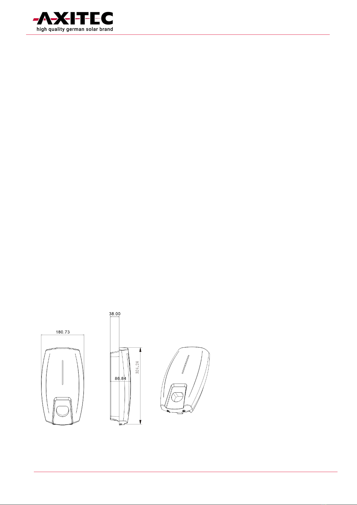
6.1 Wall mounting the housing................................................................................................................. 8
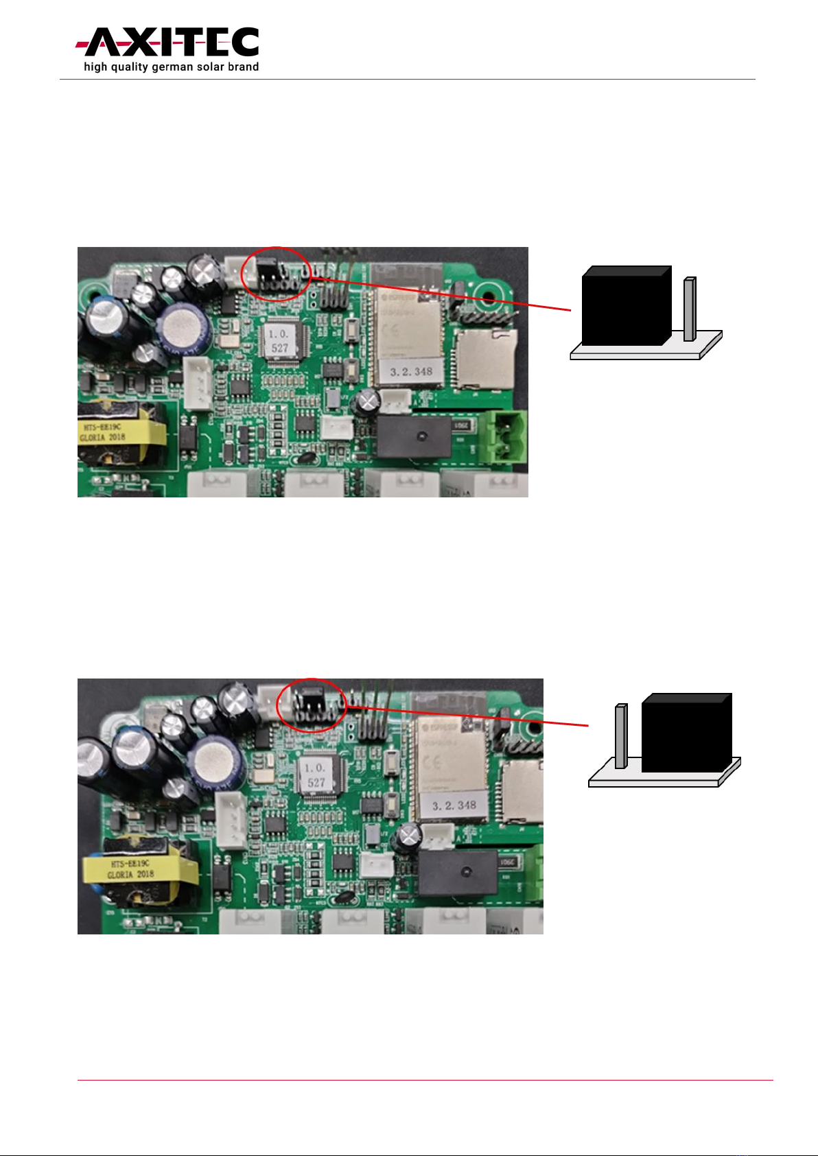
6.2 Setting the operating mode ................................................................................................................ 9
6.2.1 Control via RFID........................................................................................................................... 9
6.2.2 Plug & Play................................................................................................................................... 9
6.3 Electrical installation......................................................................................................................... 10
6.4 Final work........................................................................................................................................... 10
7TROUBLESHOOTING................................................................................................11
7.1 Error detection via LED-indicator .................................................................................................... 11
7.2 Possible solutions............................................................................................................................. 12
8DISPOSAL..................................................................................................................13

Installationsanleitung AXIbox 11K
EN211103 3
1 Target group of this document
This document refers to the assembly, installation and operation of the AXIbox 11K charging station and is
intended for the installer and the users. Chapters 5-7 are intended exclusively for the charging station
installer with the appropriate qualification.
2 General regulations and safety measures
Installation must be carried out by a qualified electrician who is familiar with the contents of the
installation instructions and knows about and can apply the applicable standards and laws. National and
regional regulations must be observed for assembly and installation.
Read these installation instructions before installation.
Read these operating instructions before operating the AXIbox 11K and ensure that this charging station is
only operated by persons who have read these instructions. Keep these instructions in a safe place.
Non-observance of these instructions as well as non-intended use of the charging station can lead to
injuries or even death as well as damage to property.
Persons with pacemakers should not carry out any installation or maintenance work on the AXIbox.
Do not operate the charging system near explosive or flammable materials, chemicals, vapours and other
hazardous objects.
Do not clean the vehicle with a pressure washer while the charging cable is connected.
Do not disconnect the charging station from the vehicle during charging.
Check the charging system for damage to the housing, cable or plug before use. A damaged wallbox must
not be put into operation.
Do not immerse the wallbox and the charging plug in water and protect the connections from moisture.
Keep the charging socket dry and clean.
When operating the charging coupler, always grasp the handle of the plug. Do not touch the contacts of the
plug or hold it by the cable.
As a user, do not open the housing of the wallbox.
No modifications or conversions may be carried out on the charging station.
No adapters or cable extensions may be used.
The input and output voltages of this unit are dangerous
high voltages that can endanger human life. Please be sure
to observe all warnings and operating instructions on the
unit and in the manual. Unauthorised and unprofessional
service personnel should not remove the cover of this unit.

Installationsanleitung AXIbox 11K
EN211103 4
The charging cable must not be kinked, pinched, run over or otherwise damaged.
Keep children away from the charging station.
The car must not be driven during charging.
3 Description oft he product
3.1 Function and intended use
The AXIbox 11K is used for charging electric cars. There is a choice of two modes, which can be set during
installation: In Plug & Play mode, no authentication by the user is necessary. Charging can be started
without unlocking after inserting the charging plug into the car's charging socket. If, on the other hand, the
charging mode with access restriction is selected, the charging process does not start automatically when
the plug is inserted, but must first be authorised by an RFID card at the wallbox or with the App. This
prevents unauthorised use.
3.2 Scope of delivery
The AXIbox 11K is delivered with the following parts:
•1 x AXIbox 11K housing with electronics and pre-installed charging cable with type 2 plug
•6 x Screws with associated expansion pipes for wall mounting
•1 x Seal for sealing the screw connection
•1 x Cable clamp for fixing the supply cable with associated screws
•1 x Cable holder
•5 x Wire end ferrules
•2 x RFID cards
•1 x Template for drilling the holes for wall mounting
•1 x Allen key for opening and closing the housing
3.3 Technical data
Charging power
11 kW
Charging current
16 A per phase
Rated voltage
400 V AC
Plug
Type 2
Cable length
7 m
Size (HxBxT)
325 x 181 x 87 mm
Weight
3,6 kg
DC fault current monitoring
>6 mA DC
Protection classes
IP65, IK10
Grid connection
3P+N+PE
400 V AC
16 A
50/60 Hz

Installationsanleitung AXIbox 11K
EN211103 5
4 Operation
4.1 Operation with Acces restriction
In this operating mode, the wallbox is locked against unauthorised use. Authentication with one of the
supplied RFID cards or control via App is required for operation.
4.1.1 Starting the charging process with RFID-Card
1. Connect the wallbox to the car to be charged via the cable. Make sure that the cable is completely
unwound. The LED flashes yellow every 1 second.
2. Unlock the wallbox by holding the RFID card at the point marked "CARD" on the housing of the
AXIbox.
3. The charging process starts. During the charging process, the LED flashes green every 1 second.
4.1.2 Ending the charging process
1. Stop the charging process at the car. When the car is fully charged, charging will stop.
2. Disconnect the charging plug from the vehicle and stow it at the wallbox.
4.1.3 Control via App
The AXIbox can be controlled via the Chargein app. The charging process can be started and stopped, and a
charging schedule can be created. The variation of the charging current is also possible via the app. The
RFID cards can also be integrated into the app and additional users can be activated. Illustrated instructions
for connecting to the app are enclosed with the unit (Charger Network Configuration).
Installation and Sign in
•Download the Chargein App
•Create an account
•Sign in to your account
Connect with the AXIbox 11K
•Requirements: 2,4 GHz W-LAN; Bluetooth, W-LAN and location must be activated at the
smartphone
•Select your Charger under User / Charger Management / Add Charger and confirm the serial
number.
•Connect to your W-LAN
•After 10 to 60s, the AXIbox should be online, in the main menu it should show “In Standby”.
•Now, the charger can be controlled with the App.
ATTENTION: Do not activate Load Balance!
4.2 Plug & Play mode
No authentication is required in this operating mode.
4.2.1 Starting the charging process
1. Connect the wallbox to the car to be charged via the cable. Make sure that the cable is completely
unwound.
2. Start the charging process on the vehicle. During the charging process, the LED flashes green every
1 second.

Installationsanleitung AXIbox 11K
EN211103 6
4.2.2 Ending the charging process
1. Stop the charging process at the car. When the car is fully charged, charging will stop.
2. Disconnect the charging plug from the vehicle and stow it in the wallbox.
4.3 Changing the operation mode
The change between the operating modes Plug & Play and operation with RFID card can only be carried out
by an electrician. The change that must be made to the internal electronics is described under Fehler!
Verweisquelle konnte nicht gefunden werden..
4.4 Behaviour in the event of an error
In the event of a fault, switch off the associated building-side fuse of the charging system and thus
disconnect it from the power supply. Ensure that the fuse is not switched on again before rectifying the
fault. Contact a qualified electrician.

Installationsanleitung AXIbox 11K
EN211103 7
5 Requirements
5.1 Electrical requirements
When making the electrical connection, the country-specific regulations, standards and application rules
must be observed.
5.1.1 Supply cable
The power supply of the wallbox must be three-phase (3P + N + PE; min. 5 x 2,5 mm2, depending on the
locally applicable regulations, environmental conditions and installation type). The required conductor
voltage is 400 V AC and a current of 16 A per phase with 50 Hz mains frequency.
5.1.2 Protection devices
The phases of the supply line must each be protected with miniature circuit breakers and residual current
devices. The national regulations must be observed when dimensioning the miniature circuit breakers and
residual current devices.
The AXIbox 11K has residual current monitoring for currents >6 mA DC. Therefore, the charging station
must be fused with an RCD with at least type A. No other circuits may be connected to the residual current
circuit breaker.
5.2 Requirements for the installation site
To control the AXIbox with the app, a W-Lan connection with 2.4 GHz is required at the installation site.
The AXIbox may only be mounted and operated vertically.
Mounting is permitted up to a maximum altitude of 2000 m above sea level.
The ambient temperature must not fall below -30°C and must not exceed 50°C.
The humidity must be in the range between 5% and 95%.
Do not install the charging station near explosive or flammable substances.

Installationsanleitung AXIbox 11K
EN211103 8
6 Installation
Electrical device should be installed, operated, serviced, and maintained only by qualified personnel. No
responsibility is assumed by the manufacturer for any consequences arising out of the use of this device. A
qualified person is one who has skills and knowledge related to the construction, installation and operation
of electrical device and who has received safety training to recognize and avoid the hazards involved.
All applicable local, regional, and national regulations must be respected when installing, repairing, and
maintaining this device.
6.1 Wall mounting the housing
To mount the AXIbox on the wall, follow the steps below:
1. Align the drilling template horizontally on the wall and mark the 3 drill holes on the wall.
2. Drill the 3 holes for the wall mounting of the wallbox and, if necessary, also the 3 holes for the
cable holder. The top two screws can already be fastened in the wall with the expansion pipes so
that the AXIbox can be hung from them later.
3. Open the two screws on the underside of the AXIbox to open the housing.
4. Hang the back of the housing on the two screws on the wall and fix the AXIbox in the wall with the
third screw.
5. Seal the hole for the screw with the seal included in the scope of delivery.

Installationsanleitung AXIbox 11K
EN211103 9
6.2 Setting the operating mode
The AXIbox has two operating modes. The changeover may only be carried out by a specialist, taking into
account all necessary safety precautions.
6.2.1 Control via RFID
When delivered, the AXIbox is protected against unauthorised use by a lock. The charging process is started
by the RFID cards supplied. If this operating mode is desired, no changes need to be made.
In order to use the RFID cards to activate the charging process, the jumper marked in the above image must
be in the position shown. If the AXIbox was previously in Plug & Play mode, the jumper must be moved
back to the position shown above to switch to RFID mode.
6.2.2 Plug & Play
In Plug & Play mode, charging can be started after inserting the charging plug into the car's charging socket
without further activation. To switch to this mode, the jumper marked in the image below must be placed
in the position shown.

Installationsanleitung AXIbox 11K
EN211103 10
6.3 Electrical installation
The electrical supply to the wallbox is three-phase, a cable with 3 conductor phases, a neutral conductor
and a PE conductor is required.
Feed the cable through the left-hand opening at the bottom of the AXIbox housing. Clamp the wires of the
cable into the terminals provided. Use the wire end ferrules supplied and fix the cable inside the AXIbox
with the sleeve.
Schematic representation of the wiring
6.4 Final work
Put the housing cover back on the base and close the housing again with the two screws. The AXIbox is now
ready for use as soon as the power supply is switched on.
Before commissioning, check the following:
•Der gewählte Standort gewährleistet eine einfache Bedienung und Reparatur
•Die Ladestation wurde ordnungsgemäß installiert
•Die Schutzschalter der Zuleitung sind angemessen
•Es liegen keine Geräte und Gegenstände auf der Ladestation

Installationsanleitung AXIbox 11K
EN211103 11
7 Troubleshooting
7.1 Error detection via LED-indicator
State
Description
LED State
Standby
Normal
Flashing green, 1S on, 4S off
Charging
Normal
Breathing green, 1S on, 1S off
Cable connected
Normal
Breathing yellow, 1S on, 1S off
Software upgrade
Normal
Green light flash
Ground warning
Normal
Flashing yellow, 2S on, 2S off
Relay adhesion
Fault
Red light normally on
Input polarity reverse
Fault
Flashing red, 500ms on, 500ms off, 1 time, 3S off, Cycle
CP fault
Fault
Flashing red, 500ms on, 500ms off, 2 times, 3S off, Cycle
Leakage current fault
Fault
Flashing red, 500ms on, 500ms off, 3 times, 3S off, Cycle
Input terminal
overtemperature
Fault
Flashing red, 500ms on, 500ms off, 4 times, 3S off, Cycle
Relay overtemperature
Fault
Flashing red, 500ms on, 500ms off, 5 times, 3S off, Cycle
Under voltage fault
Fault
Flashing red, 500ms on, 500ms off, 6 times, 3S off, Cycle
Over voltage fault
Fault
Flashing red, 500ms on, 500ms off, 7 times, 3S off, Cycle
Overload fault
Fault
Flashing red, 500ms on, 500ms off, 8 times, 3S off, Cycle
Over frequency fault
Fault
Flashing red, 500ms on, 500ms off, 9 times, 3S off, Cycle
Other frequency fault
Fault
Flashing red, 500ms on, 500ms off, 10 times, 3S off, Cycle
Leakage current loop
abnormal
Fault
Flashing red, 500ms on, 500ms off, 11 times, 3S off, Cycle

Installationsanleitung AXIbox 11K
EN211103 12
7.2 Possible solutions
Problems
Possible Causes
Solutions
Input over voltage
AC input voltage may be too
high.
1. Check the input voltage from the backend.
2. If the voltage is over 276Vac for a short time,
wait till the power grid recovers to normal voltage
range.
Input low voltage
AC input voltage may be too
low.
1. Check the input voltage from the backend.
2. If the voltage is under 184Vac for a short time,
wait till the power grid recovers to normal voltage
range.
Output overload
AC output current may be too
large.
1. Shut off the leakage current protection switch of
power distribution cabinet immediately.
2. Check whether there is low resistance connection
between AC output cables of the charger.
Input over frequency
AC input frequency may be too
high.
1. Check the input voltage frequency from the
backend.
2. If the frequency exceeds 63Hz for a short time,
wait till power grid recover to normal voltage
range.
Input low frequency
AC input frequency may be too
low.
1. Check the input voltage frequency from the
backend.
2. If the frequency is lower than 47Hz for short
time, wait till power grid recover to normal voltage
range.
Over temperature
Temperature may be too low
inside the charger.
1. Check the surrounding conditions of chargers
installed whether there is heating device nearby.
Make sure environmental temperature is under
60℃.
Over leakage current
Leakage current to the earth
may be too high.
1. Shut off the leakage current protection switch of
power distribution cabinet immediately.
2. Check whether there is broken of AC output
cables or low resistance connection to the earth.
Reverse connection
Reverse connection of L/N
input cable.
1. Shut off the leakage current protection switch of
power distribution cabinet immediately.
2. Check if AC input/output cables are normal, and
if inverse connection of L/N input cables.
Charging cable connection
abnormal
Poor connection of charging
cable with EV/Charger.
1. Check if charging cable connection is correct and
firm.

Installationsanleitung AXIbox 11K
EN211103 13
8 Disposal
The AXIbox is subject to the EU Directive 2012/19/EU on Waste Electrical and Electronic Equipment (WEEE).
The AXIbox must therefore not be disposed of with household waste, but must be disposed of in
accordance with national and regional regulations for electrical and electronic equipment. The unit should
be rendered inoperable before disposal.
Table of contents