Axpert MLV-5KW-48V User manual

LV 5KVA-48V
INVERTER / CHARGER
Version: 1.0
User Manual

Table of Contents
ABOUT THIS MANUAL ..................................................................................................................... 1
Purpose............................................................................................................................................. 1
Scope................................................................................................................................................ 1
SAFETY INSTRUCTIONS.................................................................................................................. 1
INTRODUCTION.............................................................................................................................. 2
Features ............................................................................................................................................ 2
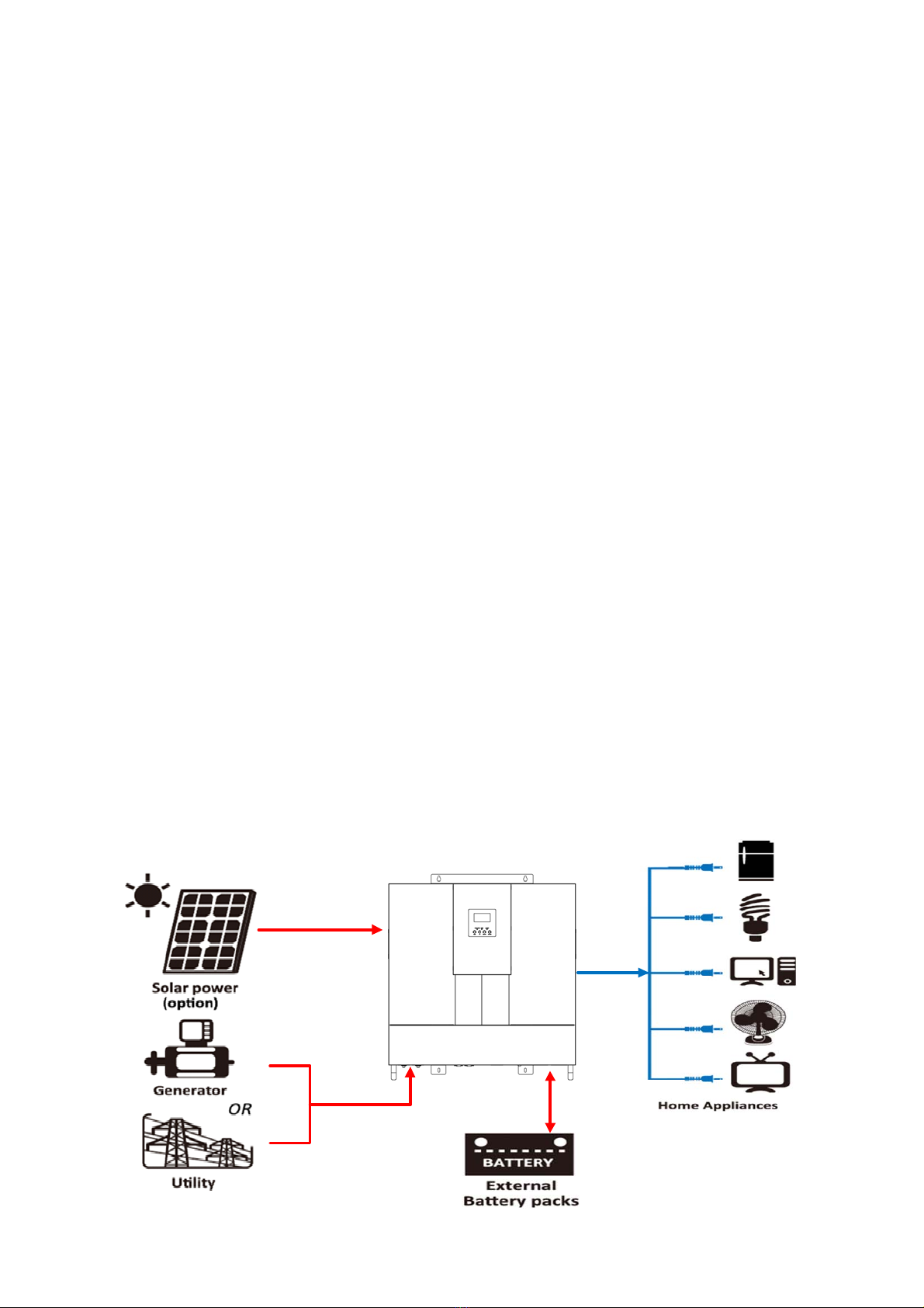
Basic System Architecture ................................................................................................................... 2
Product Overview ............................................................................................................................... 3
INSTALLATION................................................................................................................................ 4
Unpacking and Inspection ................................................................................................................... 4
Preparation ........................................................................................................................................ 4
Mounting the Unit............................................................................................................................... 4
Battery Connection ............................................................................................................................. 6
AC Input/Output Connection................................................................................................................ 7
PV Connection.................................................................................................................................... 9
Final Assembly ................................................................................................................................. 10
Communication Connection ............................................................................................................... 12
Dry Contact Signal............................................................................................................................ 12
OPERATION................................................................................................................................... 13
Power ON/OFF ................................................................................................................................. 13
Operation and Display Panel .............................................................................................................. 13
LCD Display Icons............................................................................................................................. 14
LCD Setting...................................................................................................................................... 16
Display Setting ................................................................................................................................. 23
Operating Mode Description .............................................................................................................. 25
Fault Reference Code........................................................................................................................ 27
Warning Indicator............................................................................................................................. 28
SPECIFICATIONS .......................................................................................................................... 29
Table 1: Line Mode Specifications ...................................................................................................... 29
Table 2: Inverter Mode Specifications................................................................................................. 30
Table 3: Charging Mode Specifications................................................................................................ 31
Table 4 General Specifications ........................................................................................................... 32
TROUBLESHOOTING ..................................................................................................................... 33
Appendix I: Approximate Back-up Time Table............................................................................. 34
Appendix II: Parallel function....................................................................................................... 35

1
ABOUT THIS MANUAL
Purpose
This manual describes the assembly, installation, operation and troubleshooting of this unit. Please read
this manual carefully before installations and operations. Keep this manual for future reference.
Scope
This manual provides safety and installation guidelines as well as information on tools and wiring.
SAFETY INSTRUCTIONS
WARNING: This chapter contains important safety and operating instructions. Read and
keep this manual for future reference.
1. Before using the unit, read all instructions and warnings marked on the unit, the batteries and all
appropriate sections of this manual.
2. CAUTION --To reduce risk of injury, charge it with only deep-cycle lead acid type rechargeable
batteries. It might cause burst or result in physical injury and damage if you charge it with other types
of the batteries.
3. Do not disassemble the unit at will. For servicing or repairs, it’s advised to take it to an authorized
service center. Incorrect re-assembly may result in a risk of electric shock or fire.
4. To reduce the risk of electric shock, unplug all wirings from the wall outlet before any maintenance or
cleaning. Turning off the unit will not reduce this risk.
5. CAUTION – Only qualified personnel can install this device with battery.
6. NEVER charge a frozen battery.
7. For optimum operation of this inverter/charger, please follow required spec to select appropriate cable
size. It’s very important to correctly operate this inverter/charger.
8. Be very cautious when working with metal tools on or around the batteries. A potential risk exists when
you drop tools on or around the batteries. Spark, short circuited batteries or other electrical parts might
cause an explosion.
9. Please strictly follow installation procedure when you want to disconnect AC or DC terminals. Please
refer to the INSTALLATION section of this manual for the details.
10. Fuses are provided for over-current protection of the battery supply.
11. GROUNDING INSTRUCTIONS -This inverter/charger should be connected to a permanent grounded
wiring system. Be sure to comply with local requirements and regulation to install this inverter.
12. NEVER cause AC output and DC input short circuited. Do NOT connect to the mains when DC input
short circuits.
13. Warning!! Only qualified service staffs are able to operate this device. If errors still persist after
following the troubleshooting table, please send this inverter/charger back to the local dealer or service
center for maintenance.

2
INTRODUCTION
This is a multi-functional inverter/charger, combining the functions of inverter, MPPT solar charger and battery
charger to offer uninterruptible power support with portability. Its comprehensive LCD display offers
user-configurable and easy-accessible button operation such as battery charging current, priority setting for
AC/solar charger, and acceptable input voltage setting to suit different applications.
Features
Pure sine wave inverter
Built-in MPPT solar charge controller
Configurable input voltage range for home appliances and personal computers via LCD setting
Configurable battery charging current to suit different applications via LCD setting
Configurable priority of AC/Solar Charger via LCD setting
Compatible to mains voltage or generator power
Automatic restart while AC is recovering
Overload/ Over temperature/ short circuit protection
Smart battery charger design to optimize battery performance
Cold start function
Basic System Architecture
The following illustration shows basic application of this inverter/charger. It also includes the following devices
to complete the whole running system:
Generator or Utility.
PV modules
Consult your system integrator for other possible system architectures depending on your requirements.
This inverter can power all kinds of appliances at home or in the office, including motor-type appliances such as
tube light, fan, refrigerator and air conditioner.
Figure 1 Hybrid Power System

3
Product Overview
1. Battery input
2. Power on/off switch
3. Dry contact
4. USB communication port
5. RS232 communication port
6. PV input
7. Parallel communication port (only for parallel model)
8. Current sharing port (only for parallel model)
9. Parallel ID
10. AC output
11. Circuit breaker
12. AC input
13. LCD display
14. Status indicator
15. Charging indicator
16. Fault indicator

4
INSTALLATION
Unpacking and Inspection
Before installation, please inspect the unit. Be sure that nothing inside the package is damaged. You should
have received the following items inside the package:
The unit x 1
User manual x 1
Communication cable x 1
Software CD x 1
Preparation
Before connecting all wirings, please take off the cover of the bottom by removing the six screws as shown
below.
Mounting the Unit
Consider the following points before selecting where to install:
Do not mount the inverter on any flammable construction
materials.
Mount this inverter on a solid surface
Install this inverter at eye level in order to read the LCD display at
all times.
The ambient temperature should be between 0°C and 55°C to
ensure optimal operation.
The inverter should be adhered to the wall vertically.
Be sure to keep other objects away and leave the space in a
minimum as shown in the right diagram to guarantee sufficient
heat dissipation and enough space for replacing wires.
SUITABLE FOR MOUNTING ON CONCRETE OR OTHER NON-COMBUSTIBLE SURFACE ONLY.
Install the unit by screwing four screws as shown in the diagram.
It’s recommended to use M5 screws.

5

6
Battery Connection
CAUTION: For safety operation and regulation compliance, it’s requested to install a separate DC over-current
protector or disconnect the device between battery and inverter. It may not be necessary to disconnect the
device for some applications, however, it’s requested to have over-current protection installed. Please refer to
the typical amperage in the table below as required fuse or size of the breaker.
WARNING! All wiring must be performed by a qualified personnel.
WARNING! It's very important for system safety and efficient operation to use
appropriate cable for battery connection. To reduce risk of injury, please use proper
cables and suitable size of terminal recommended below.
Recommended battery cables and size of terminal:
Model Typical
Amperage Battery
Capacity Wire Size Ring Terminal Torque
Value
Cable
mm2Dimensions
D (mm) L (mm)
5KW 220A 200AH
1*1/0AWG 60 8.4 49.7 5~6 Nm
2*4AWG 44 8.4 49.7
Please follow the steps below to implement the battery connection:
1. Assemble battery ring terminal based on recommended battery cable and terminal size.
2. Connect all battery packs as units requires. It’s suggested to connect at least 200Ah capacity battery for
5KW model.
3. Insert the ring terminal of battery cable flatly into battery connector of inverter and make sure the bolts are
tightened with torque of 5-6 Nm. Make sure polarity at both the battery and the inverter is correctly
connected and ring terminals are tightly screwed to the battery terminals.
4. Connect all battery packs as below chart.
Ring terminal:

7
WARNING: Shock Hazard
Installation must be performed with care due to high battery voltage in series.
CAUTION!! Do not place anything between the flat part of the inverter terminal and the ring
terminal. Otherwise, overheating may occur.
CAUTION!! Do not apply any anti-oxidant substance on the terminals before the terminals are
connected tightly.
CAUTION!! Before making the final DC connection or closing DC breaker/disconnector, be sure
positive (+) must be connected to positive (+) and negative (-) must be connected to negative
(-).
AC Input/Output Connection
CAUTION!! Before connecting to AC input power source, please install a separate AC breaker between
inverter and AC input power source. This will ensure the inverter can be securely disconnected during
maintenance and fully protected from over current of AC input. The recommended spec of AC breaker is 40A
for 5KVA.
CAUTION!! There are two terminal blocks with “IN” and “OUT” markings. Please do NOT mis-connect input
and output connectors.
WARNING! All wiring must be performed by the qualified personnel.
WARNING! The AC input N wire must be connected, Otherwise, the inverter will NOT detect AC input;
WARNING! It's very important for system safety and efficient operation to use appropriate cable for AC input
connection. To reduce risk of injury, please use the recommended cable size as below.
Suggested cable requirement for AC wires
Model Gauge Torque Value
5KVA 10 AWG 1.4~ 1.6Nm
There are three applications for different AC input as shown in the figure below. For phase angle operation,
please refer to LCD #28

8
MLV 5KW
L1
N
Grid
connection Load
Output
L1
N
L2 L2
L1
L2
N
L1
N
120V
120V
120V
120V
L2
0V 0V
When the phase angle between L1 and L2 is 0°.
MLV 5KW
L1
N
Grid
connection Load
Output
L1
N
L2 L2
L1
L2
N
L1
N
120V
120V
120V
120V
L2
208V 208V
When the phase angle between L1 and L2 is 120°.
MLV 5KW
L1
N
Grid
connection Load
Output
L1
N
L2 L2
L1
L2
N
L1
N
120V
120V
120V
120V
L2
240V 240V
When the phase angle between L1 and L2 is 180°.
Please follow below steps to implement AC input/output connection:
1. Before making AC input/output connection, be sure to open DC protector or disconnector first.
2. Remove insulation sleeve 10mm from the six conductors. And short-circuit phase L and neutral conductor N
3 mm.
3. Insert AC input wires according to polarities indicated on terminal block and tighten the terminal screws. Be
sure to connect PE protective conductor ( ) first.
→Ground (yellow-green)
L1→LINE (black)
L2→LINE (brown)
N→Neutral (blue)

9
WARNING:
Be sure that AC power source is disconnected before attempting to hardwire it to the unit.
4. Then, insert AC output wires according to polarities indicated on terminal block and fasten the terminal
screws. Be sure to connect PE protective conductor ( ) first.
→Ground (yellow-green)
L1→LINE (black)
L2→LINE (brown)
N→Neutral (blue)
5. Make sure the wires are securely connected.
PV Connection
CAUTION: Before connecting to PV modules, please install separately a DC circuit breaker between inverter
CAUTION: Important
Be sure to connect AC wires with correct polarity. If L and N wires are connected reversely, it may cause
utility short-circuited when these inverters are worked in parallel operation.
CAUTION: Appliances such as air conditioner are required at least 2~3 minutes to restart because it’s required
to have enough time to balance refrigerant gas inside of circuits. If a power shortage occurs and recovers in a
short time, it will cause damage to your connected appliances. To prevent this kind of damage, please check with
the manufacturer of the air conditioner if it’s equipped with time-delay function before installation. Otherwise,
this inverter/charger will cause overload fault and cut off the output to protect your appliance but sometimes it
still causes internal damage to the air conditioner.

10
and PV modules.
WARNING! All wiring must be performed by a qualified personnel.
WARNING! It's very important for system safety and efficient operation to use appropriate cable for PV
module connection. To reduce risk of injury, please use the recommended cable size as below.
NOTICE! When only one MPPT is used, please use MPPT1 first.
Model Typical Amperage Cable Size Torque
5KVA 80A 8 AWG 1.4~1.6 Nm
PV Module Selection:
When selecting proper PV modules, please be sure to consider the parameters below:
1. Open circuit Voltage (Voc) of PV modules can’t exceed the maximum voltage of the PV array open circuit of
the inverter.
2. Open circuit Voltage (Voc) of PV modules should be higher than the minimum voltage of the battery.
Please follow the steps below to implement PV module connection:
1. Remove insulation sleeve 10 mm from positive and negative conductors.
2. Check the correct polarity of connected cable from PV modules and PV input
connectors. Then, connect positive pole (+) of connection cable to positive
pole (+) of PV input connector. Connect negative pole (-) of connection
cable to negative pole (-) of PV input connector.
3. Make sure the wires are securely connected.
Final Assembly
After connecting all wirings, please put the bottom cover back by fixing two screws as shown below.
Solar Charging Mode
Solar Charger Type MPPT
Number of MPPT 2
Max. PV Array Open Circuit Voltage 145Vdc
PV Array MPPT Voltage Range 60~115Vdc
Min. battery voltage for PV charge 34Vdc

11

12
Communication Connection
Please use supplied communication cable to connect to inverter and PC. Insert bundled CD into a computer and
follow the on-screen instructions to install the monitoring software. For the detailed software operations,
please check user manual of software inside the CD.
Dry Contact Signal
There is one dry contact (3A/120VAC) available on the rear panel. It could be used to deliver signal to external
device when battery voltage reaches warning level.
Unit
Status Condition Dry contact port:
NC & C NO & C
Power Off Unit is off and no output is powered. Close Open
Power On
Output is powered from Utility. Close Open
Output is
powered
from Battery
or Solar.
Program
01 set as
Utility
Battery voltage < Low DC warning
voltage Open Close
Battery voltage > Setting value in
Program 13 or battery charging
reaches floating stage
Close Open
Program
01 is set
as SBU or
Solar first
Battery voltage < Setting value in
Program 12 Open Close
Battery voltage > Setting value in
Program 13 or the battery
charging reaches the floating
stage
Close Open
Parallel ID
1 2 3 4 Parallel ID
OFF OFF OFF * 0
ON OFF OFF * 1
OFF ON OFF * 2
ON ON OFF * 3
OFF OFF ON * 4
ON OFF ON * 5
OFF ON ON * 6
ON ON ON * 7
* Not used

13
OPERATION
Power ON/OFF
Once the unit has been properly installed and the batteries are connected well, simply press On/Off switch
(located on the right corner of the rear panel) to turn on the unit.
Operation and Display Panel
The operation and display panel, as shown in the chart below, are on the front panel of the inverter. It
includes three indicators, four function keys and an LCD display, indicating the operating status and
input/output power information.
LED Indicator
LED Indicator Messages
Green Solid On Output is powered by utility in Line mode.
Flashing Output is powered by battery or PV in battery mode.
Green Solid On Battery is fully charged.
Flashing Battery is charging.
Red Solid On Fault occurs in the inverter.
Flashing Warning occurs in the inverter.
Function Keys
Function Key Description
ESC To exit setting mode
UP To go to previous selection
DOWN To go to next selection
ENTER To confirm the selection in setting mode or enter setting mode
LCD display
LED indicators
Function keys

14
LCD Display Icons
Icon Function description
Input Source Information
Indicates the AC input.
Indicates the PV input
Indicates the input 1, output 1.
Indicates the input 2, output 2.
Indicates input voltage, input frequency, PV voltage, battery voltage and
charger current.
Configuration Program and Fault Information
Indicates the setting programs.
Indicates the warning and fault codes.
Warning: flashing with warning code.
Fault: lighting with fault code
Output Information
Indicate output voltage, output frequency, load percent, load in VA, load in
Watt and discharging current.
Battery Information
Indicates battery level by 0-24%, 25-49%, 50-74% and 75-100% in battery
mode and charging status in line mode.
In AC mode, it will present battery charging status.
Status Battery voltage LCD Display
Constant
Current mode /
Constant
<2V/cell 4 bars will flash in turns.
2 ~ 2.083V/cell Bottom bar will be on and the other three
bars will flash in turns.
2.083 ~ 2.167V/cell Bottom two bars will be on and the other
two bars will flash in turns.

15
Voltage mode > 2.167 V/cell Bottom three bars will be on and the top
bar will flash.
In floating mode, batteries are fully charged. 4 bars will be on.
In battery mode, it will present battery capacity.
Load Percentage Battery Voltage LCD Display
Load >50%
< 1.717V/cell
1.717V/cell ~ 1.8V/cell
1.8 ~ 1.883V/cell
> 1.883 V/cell
50%> Load > 20%
< 1.817V/cell
1.817V/cell ~ 1.9V/cell
1.9 ~ 1.983V/cell
> 1.983
Load < 20%
< 1.867V/cell
1.867V/cell ~ 1.95V/cell
1.95 ~ 2.033V/cell
> 2.033
Load Information
Indicates overload.
Indicates the load level by 0-24%, 25-50%, 50-74% and 75-100%.
0%~25% 25%~50% 50%~75% 75%~100%
Mode Operation Information
Indicates unit connects to the mains.
Indicates unit connects to the PV panel.
Indicates load is supplied by utility power.
Indicates the utility charger circuit is working.
Indicates the DC/AC inverter circuit is working.
Indicates the PV charger circuit is working.

16
Mute Operation
Indicates the alarm is disabled.
LCD Setting
After pressing and holding the ENTER button for 3 seconds, the unit will enter setting mode. Press “UP” or
“DOWN” button to select setting programs. And then, press “ENTER” button to confirm the selection or ESC
button to exit.
Setting Programs:
Program Description Selectable option
00 Exit setting mode
Escape
01
Output source priority:
To configure load power
source priority
Solar first
Solar energy provides power to the
loads as first priority.
If solar energy is not sufficient to
power all connected loads, battery
energy will supply power to the loads
at the same time.
Utility provides power to the loads
only when any one condition stated
below happens:
- Solar energy is not available
- Battery voltage drops to either low
DC warning voltage or the setting
point in program 12.
Utility first (default)
Utility will provide power to the loads
as first priority.
Solar and battery energy will provide
power to the loads only when utility
power is not available.
SBU priority
Solar energy provides power to the
loads as first priority.
If solar energy is not sufficient to
power all connected loads, battery
energy will supply power to the loads
at the same time.
Utility provides power to the loads
only when battery voltage drops to
either low DC warning voltage or the
setting point in program 12.
02
Maximum charging current:
To configure the total
charging current for solar
and utility chargers.
(Max. charging current =
utility charging current +
solar charging current)
20A
30A

17
02
Maximum charging
current: To configure the
total charging current for
solar and utility chargers.
(Max. charging current =
utility charging current +
solar charging current)
40A
50A
60A 70A
80A 90A
100A 110A
120A
130A (only for 5KVA with MPPT
models)
140A
150A
160A
170A
180A
190A
200A
210A
220A
03 AC input voltage range
Appliances (default) If selected, acceptable AC input
voltage range will be within
90-280VAC.
UPS If selected, acceptable AC input
voltage range will be within
170-280VAC.
05 Battery type
AGM (default) Flooded

18
User-Defined
If “User-Defined” is selected, battery
charge voltage and low DC cut-off
voltage can be set up in program 26,
27 and 29.
06 Automatically restart when
overload occurs
Restart disable
(default)
Restart enable
07 Automatically restart when
over temperature occurs
Restart disable
(default)
Restart enable
08 Output voltage
110V 120V (default)
09 Output frequency
50Hz (default) 60Hz
11 Maximum utility charging
current
2A 10A
20A 30A (default)
40A 50A
60A
12
Setting voltage point back
to utility source when
selecting “SBU priority” or
“Solar first” in program 01.
44.0V
45.0V (default)
46.0V
47.0V
48.0V
49.0V
50.0V
51.0V
Table of contents
Other Axpert Batteries Charger manuals