Axmin UE-153DV1 User manual


Table of Contents
1. General Safety Rules .............................................................................................................1
Electrical schematic .................................................................................................................2
Before cutting...........................................................................................................................3
Pump grease ...........................................................................................................................3
2. The Quick Vise and Work Set Up ..........................................................................................3
Usage of the vise .....................................................................................................................3
Work set up..............................................................................................................................3
3. Special Safety Rules for Metal Saw ......................................................................................4
Before using the saw ...............................................................................................................4
Before each use.......................................................................................................................4
Whenever saw is running.........................................................................................................5
4. Power Supply .........................................................................................................................5
Motor specifications .................................................................................................................5
Earth ........................................................................................................................................6
Motor safety protection.............................................................................................................6
Wire sizes ................................................................................................................................6
5. Unpacking and Checking Contents ......................................................................................6
6. Description and Characteristics ...........................................................................................7
7. Operating................................................................................................................................7
Information before operation ....................................................................................................7
Auto cutting..............................................................................................................................8
Manual cutting ........................................................................................................................8
Angle cutting ............................................................................................................................8
Changing blade........................................................................................................................9
Magnetic switch .....................................................................................................................10
8. Adjusting ..............................................................................................................................10
Adjusting blade guide.............................................................................................................10
Adjusting poor cutting ............................................................................................................10
Changing the motor carbons brushes ....................................................................................11
9. Part List & Explosion Drawings ..........................................................................................12

- 1 -
1. General Safety Rules
WARNING
1. Read and understand instructions of this manual entirely before operating the machine.
2. Always wear approved safely glasses /face shields when using the machine.
3. Make certain the machine is properly grounded.
4. Before machine in operation, remove tie, ring, watch, other jewelry, and roll your sleeves up to
above elbows. Remove loose clothing and confine long hair.
5. Keep the floor around this machine clean and free of scrap material, oil and grease.
6. Keep machine guards in place at all times when the machine is in use. If it removed for
maintenance purpose, pay extra attention and replace these guards at once.
7. Do not over reach. Keep a balanced stance all the time so that you don’t fall lean against
blade or some other moving parts.
8. Whenever make any adjustments or maintenance with the machine must unplug the power
source.
9. Use the right tool. Don’t force a tool or attachment to do a job that it was not designed for.
10. Replace warning labels if they have become obscured or removed.
11. Make certain the motor switch is in “off” position while connecting the machine into the power
supply.
12. Pay your work undivided attention. Looking around, and carrying on a conversation, or
“Horse-play” are careless acts, which might result in serious injury.
13. Keep visitors a safe distance from the work area.
14. Use recommended accessories, and parts. Improved accessories may be hazardous.
15. From the good habit of checking, to see keys and wrenches are removed before turning on
this machine.
16. Always keep hands & fingers away from the black when this machine is running.
17. Never hold a material with this saw in the horizontal position. Please be sure always use the
vise to clamp it securely.
18. Read and understand warnings that posted on the machine.
19. Always provide necessary support for long and heavy material.
20. Use a sharp blade and always keep machine clean for a best and safest performance.
21. Failure to comply with any of these warnings may cause serious injury.

- 2 -
Electrical Schematic

- 3 -
Before Cutting
Fig. 1
Release the lock pin (A) in Fig.1 to free this saw.
After service, must relock in the pin to the saw
head properly for your safety and carry. Failure
to comply with the warning could result in
personal injury and machine damage
Pump Grease
ATTENTION
Pump grease into the gear reducer every
week to lubricate the gears avoid gears got
high temperature when machine be used
continuously.
Choose super high-density grease.
Grease nipple located at rear of gear reducer.
Use grease gun pump in grease from grease
nipple.
2. The Quick Vise and Work Set
Up
Usage of the Vise
The vise is mounted on the machine base.
Follow the easy steps to open or close the vise.
Fig. 2
1. Turn the handle (A) in Fig.2 counter
clock-wise to open the vise jaw to allow the
width of vise can load work piece.
2. Make sure the work piece is well located on
the table. Turn the handle (A) clock-wise to
close the vise jaw to clamp the work piece.
CAUTION !
NEVER OPERATE SAW WITHOUT BLADE
GUARDS IN PLACE.
Work Set Up
1. Raise saw head to proper position in Fig.3.
2. Open vise to accept the piece to be cut by
turning the hand lever to open the vise.
3. Place work piece on saw bed if the piece is
long, support the end.
Fig.3
A
A
Grease Nipple

- 4 -
3. Special Safety Rules for Metal
Saw
WARNING: For your own safety, do not
operate your metal saw until it is
completely assembled and installed
according to the instructions…and until
you have read and understood the
following.
Before Using the Saw
1. Assembly and alignment.
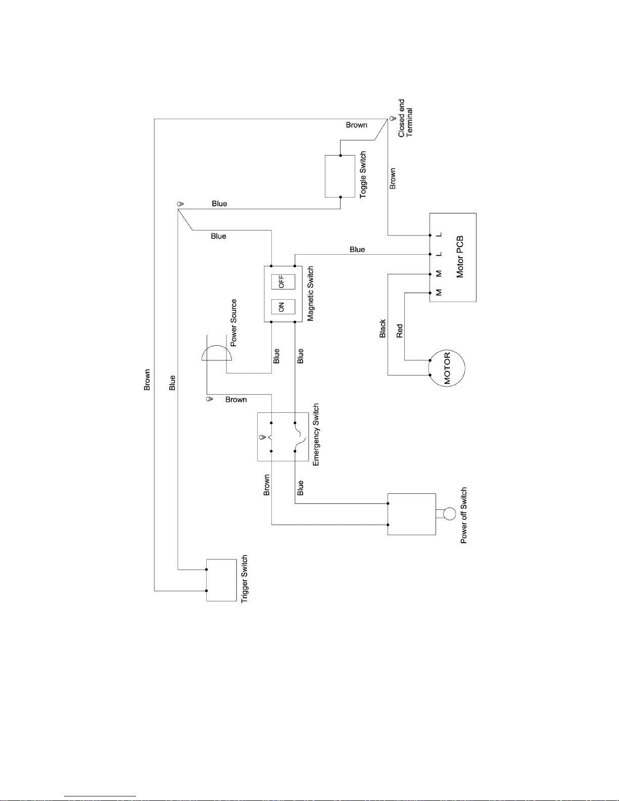
2. Learn the function and proper use of:
A. The on-off start switch, trigger switch,
blade speed knob and stop button.
B. The lower blade guards.
C. The fixing saw bow latch.
D. The bevel clamp, fence clamps, and
metal lock handle.
3. Read and understand all safety instructions
and operating procedures throughout the
manual.
4. Read the warning labels on the metal saw.
Before Each Use
1. Inspect your saw. If any part of this metal
saw was missing, or bent, or has failed in
any way, or any electrical parts do not work
properly, turn the saw off and unplug the
saw. Replace damaged, missing, or failed
parts before using the saw again.
2. Plan your work to protect your eyes, hands,
face and ears.
A. Wear safety goggles (not glasses) that
comply with DIN 58214 (show on
package). Using any power tool can
result in foreign objects being thrown
into the eyes, which can result in
permanent eye damage. Goggles are
available at stores. Use of glasses or
use of goggles not in compliance with
DIN 58214 could result in severe injury
from breakage of the eye protection.
B. For dusty operations, wear a face
shield along with safety goggles.
C. To avoid injury from jams, slips or
thrown piece:
˙It is important to choose the right
blade for the material and the type
of cutting you plan to do. This saw
is equipped with a bi-metallic
blade which can be used to cut
stainless steel, steel, iron, brass,
aluminum, wood, plastic and so
on.
˙Make sure the direction of rotation
arrow on the blade matches the
direction arrow on the saw. The
blade teeth should always point
downward at the front of the saw.
˙Make sure the blade is sharp,
undamaged and properly aligned.
With the saw unplugged, push the
power-head all the way down.
Head spin the blade and check for
clearance. If the blade hits
anything, make the adjustments
shown in the Maintaining
Maximum Cutting Capacity
section.
˙Make sure the blade and arbor
collars are clean.
˙Make sure all clamps and locks
are tight and there is no excessive
play in any parts.
˙Never cut freehand:
a. Brace your work piece solidly
against the fence and table top so
it will not rock or twist during the
cut. Make sure no debris is caught
beneath the work piece.
b. Make sure no gaps between the
work piece, fence and table will let
the work piece shift after it is cut in
two.
c. Use jigs, fixture or a different tool
for unstable work pieces.
˙Never cut more than one work
piece at a time.
˙Make sure the cut-off piece can
move sideways after it is cut off.
Otherwise, it could be wedged
against the blade and thrown
violently.
˙Make sure bystanders are clear of
the tool and work piece. Keep
them clear of the area behind the
saw where debris will be thrown.
˙Never turn your metal saw “ON”
before clearing everything except
the work piece and related support
devices off the table.
D. To avoid risk of hearing damage, wear
earplugs or muffs during extended
period of operation.
E. To avoid being suddenly pulled into the
blade:
˙Do not wear gloves.
˙Remove all jewelry and loose
clothing.

- 5 -
˙Tie back long hair.
˙Roll long sleeves above the elbow.
F. To avoid injury from accidental starting,
always unplug saw before
disconnecting the guard, installing or
removing any blade, accessory or
attachment, or making any adjustment.
G. To avoid an electrical shock, make
sure your fingers do not touch the
metal prongs on the plug when
inserting or removing the plug to or
from a live outlet.
H. Never put lubricants on the blade while
it is spinning.
I. To avoid burns or other fire damage,
never use the saw near flammable
liquids, vapors or gases.
J. To avoid injury from unsafe
accessories use only accessories
shown on the recommended
accessories list in this manual.
Whenever Saw is Running
WARNING: Do not allow familiarity
(gained from frequent use of your metal
saw) to cause a careless mistake.
Always remember that a careless
fraction of a second is enough to cause
a severe injury.
1. Before actually cutting with the saw, let it
run for a while. If your saw makes an
unfamiliar noise or if it vibrates excessively,
stop immediately. Turn the saw off. Unplug
the saw. Do not restart until finding and
correcting the problem.
2. Never confine the piece being cut out.
Never hold it, clamp it, touch it, or use
length stops against it. It must be free to
move sideways. If confined, it could get
wedged against the blade and thrown
violently.
3. Avoid awkward hand positions where a
sudden slip could cause a hand to move
into the blade.
4. Let the blade reach full speed before
cutting.
5. Feed the saw into the work piece only fast
enough to let the blade cut without bogging
down or binding.
6. Before freeing jammed material, turn the
switch off and unplug the saw. Wait for all
moving parts to stop.
7. After finishing a cut, keep holding the power
head down, release the switch, and wait for
all moving parts to stop before moving your
hands.
WARNING: Read the following warning
labels found on the front of the saw.
DANGER
˙Keep hands out of saw blade path.
˙Never cut anything freehand.
˙Never reach behind or beneath blade.
˙To avoid electric shock, do not expose to
rain.
DANGER
˙Tighten arbor screw and all clamps
before turning power on.
4. Power Supply
Motor Specifications
The DC motor is used in this saw as the
following specifications:
Maximum capacity (kW) 0.375
Voltage (V) 115 / 230
Saw blade speed (MPM) 35~85
Blade rotating direction counter-clockwise
Weight N.W (kg) 55
WARNING: To avoid electrical hazards,
fire hazard, or damage to the tool, use
proper circuit protection or circuit breaker
to avoid shock or fire, if power cord is
worn or cut, or damaged in any way,
have it replaced immediately.
Noise information according to DIN 45635
No load under 60 dB
Working 60-65 Db

- 6 -
Earth
This metal saw is single insulated tool, so the
earth system is provided to protect you from
being shocked. The appropriate earth system is
set up as soon as this machine is plugged into
the proper power supply system. Therefore, the
standard power supply system, shall be
provided for this machine in order to protect you
from the risk of shock.
DANGER: To avoid electric shock
1. Do not change the power cord and
plug to another specification not
provided by the manufacturer.
2. Do not use in rain or where floor is
wet. This tool is intended for indoor
residential use only.
Motor Safety Protection
CAUTION: To avoid motor damage, this
motor should be blown out or vacuumed
frequently to keep sawdust from
interfering with normal motor ventilation.
1. Connect this tool with a fuse or circuit
breaker. Using the wrong size fuse can
damage the motor.
2. If the motor does not start, press the stop
button down immediately. UNPLUG THE
TOOL. Check the saw blade to make sure
it turns freely. If the blade is free, try to start
the motor again.
3. If the motor still does not start that have to
check the motor’s carbon brushes which
can be used 600~800 hours if carbon
brushes has been worn, please change the
new one.
4. If the motor suddenly stalls while cutting
material, press the stop button off, unplug
the tool, and free the blade from the
material. Then you may restart the motor
and finish the cut.
5. Fuses may “blow” or circuit breakers may
trip frequently if:
a. Motor is overloaded-overloading can
occur if you feed too rapidly or make
too many start/stops in a short time.
b. Voltage not more than 10% above or
below the nameplate voltage can
handle normal loads. For heavy loads,
however, the voltage (caused by a
small size wire in the supply circuit or
an overly long supply circuit wire) may
drop too low for the motor to operate.
Always check the connections, the
load and the supply circuit whenever
motor does not work well. Check wire
sizes and length with the Wire Size
Chart below.
6. Most motor troubles may be trace to loose
or incorrect connections, overload, low
voltage (such as small size wire in the
supply circuit) or to overly long supply
circuit wire. Always check the connections,
the load and the supply circuit whenever
motor doesn’t work well. Check wire size
and length with the Wire Size Chart below.
Wire Sizes
The use of any extension cable will cause some
loss of power. To keep this to a minimum and to
prevent overheating and motor burn-out, use the
table below to determine the minimum wire size
(lead cross-section) of an extension cable.
For circuits that are more than 40m away from
the electrical service box, the wire size must be
increased proportionately in order to deliver
ample voltage to the saw motor.
Length of the
Conductor
Wire Sizes Required
For 220V
up to 15m
15-40m
1.5mm2
2.5mm2
5. Unpacking and Checking
Contents
The Metal Saw is shipped complete in one
carton. Separate all parts from packing material,
check each item with illustration, and Make
certain all items are accounted for, before
discarding any packing material.
WARNING: If any parts are missing, do
not try to assemble the metal saw, plug
in the power cable or turn the switch on
until the missing parts are obtained and
installed correctly.

- 7 -
Fig. 4
Item
Attached Parts
Q’ty
1 Stop Rod Assembly (E) 1 set
2 Instruction Manual 1
6. Description and Characteristics
1. This 153DV small band saw is made for
your fitness to transport to any worksites.
2. The frame of this machine is cast by
aluminum and the base is by the cast iron
so that body construction becomes
stronger and smoother.
3. During operation, the noise level of this
machine is about 70 db, which is much less
than any of the other band saws, and of
course, it can present a comfortable
working environment.
4. This machine is made ready for the blade
tension adjustment by holding the handle
knob to give a little turn for the tension
increasing, or decreasing properly during
the period of blade replacement or machine
in operation. In addition, a compression
spring was attached to reduce vibration
that is from a defective work piece popping
while machine is running. It permits the
blade to be used much longer.
5. The drive of this machine is through gear
transmission that gives steadier, stronger,
and smoother cuts superior to any of pulley
drive band saws, and make less trouble
after service. Note: If anything unusual
happens on your gear transmission system,
do not try to fix or restore it personally.
Send it back to your dealer for check-up or
repair. Failure to comply can result in
machine damage.
6. The machine combines miter, and
horizontal cutting and is designed for full
efficiency and operator convenience in
each position.
WARNING
SHUT OFF THE POWER SOURCE ALL THE
TIME, BEFORE THIS MACHINE IS IN
MAINTENANCE, OPERATION, ADJUSTMENT,
OR REPAIRMENT.
WARNING
Disconnect machine from the power source!
No matter when, where, or how. Pay extra
attention to the saw during it in transportation,
operation, maintenance, or adjustment.
Failure to comply may cause serious injury!
7. Operating
Information before Operation
Be sure the blade isn’t in contact with the work
when the motor is started.
Run the motor allow the saw to come to full
speed. Begin the cut by letting the head down
slowly onto the work.
DO NOT DROP. Let the weight of the saw
provide the cutting force or use the trigger switch
handle operating by hand.
Press green button down (Fig. 5) for auto cutting,
feed rate by bow weight, the trigger switch (Fig.6)
for manual cutting.
Finished cutting or stop the cutting by press
down the red button or switch off the trigger
switch.
Fig. 5
Fig. 6
Trigger switch
ON/OFF switch
E

- 8 -
Auto Cutting
Feed Rate by spring holding
Turn toggle switch to lower location. (Fig. 7)
Select spring as outer location. (Lower photo
Fig.8) Press green button down (Fig. 5) to start
auto cutting.
Fig.7
Fig.8
Manual Cutting
Feed Rate by Handle with Trigger
Switch
Turn toggle switch to upper location. (Fig. 7)
Select spring as inner location. Screw in from
outer to inner location for 50mm (upper photo
Fig. 8)
Push down the trigger switch in for cutting
material by handle. (Fig. 9)
Fig. 9
Angle Cutting
The machine uses a swivel miter base for angle
cutting from 0~60 degree. On the sawing arm,
there is an attached angle scale (Q) in Fig.10.
This machine is preset zero degree before
leaving the factory. Angle cutting is adjusted as
follows.
1. Loosen handle (R) Fig.10 to release the
arm.
2. Move this swivel arm forward along the
scale to search a right index for the work to
be cut.
3. If the pointer matches the right index on the
scale. Tighten the handle, and a perfect
angle cut will be given.
Fig. 10
WARNING
Disconnect machine from the power source!
No matter when, where, or how. Pay extra
attention to the saw during it in transportation,
operation, and maintenance. Or adjustment.
Failure to comply may cause serious injury!
R
Q
Trigger switch
Toggle switch
Screw in
50mm
For manual cutting
For auto cutting

- 9 -
Changing Blade
1. Raise this saw head up-to proper position
by lifting up the arm Fig.11.
Fig. 11
2. Remove the blade guard by loosening two
screws (U) in Fig. 12 on the saw frame.
Fig. 12
3. Remove blade cover by loosening blade
cover’s screws on the saw frame as Fig.13.
Fig. 13
4. Turn the blade tension knob W in Fig.14,
Counter-clockwise let the blade slip off the
wheel.
Fig. 14
5. Remove blade from both wheels and blade
guides bearings in Fig.15.
Fig. 15
6. Place a new blade on the wheels but not
too tight, twist blade slightly and let it slip
into between each of guide bearings. Make
sure the teeth of blade face down toward
the bed.
7. Turn the tension knob clockwise to make
the blade tension be tensioned properly.
8. Replace blade cover in Fig.13 and guards
Fig.12.
9. Start the machine to see that the blade
runs properly.
Caution: Be sure that the machine is
disconnected from the power source before
attempting to service or take any
component away!
U
W
Blade guides bearings

- 10 -
Magnetic Switch
The band saw is equipped with magnetic switch
in Fig.16, which is designed for operating safety.
After power failure, the machine has to be
restarted by pushing the green “ON” button.
There is a red button, which depresses it to stop
all machine functions.
Fig. 16
8. Adjusting
Adjusting Blade Guide
An unbounded handle (A) in Fig.17 is mounted
on the unit for freely changing blade guide
device position by loosens it counter- clockwise.
Fig. 17
It’s designed for your convenience to adjust
blade guide easily and quickly at any time, and
under any situation. Adjustment of this blade
guide is in accordance with the sizes of work
pieces. The one located at the left of the saw
head can be adjusted and the other is fixed.
When cutting a small work, move the guide
toward the work as close as it can be. Both
cuttings will present you satisfactory jobs.
WARNING
Do not make any adjustments, or load, unload
work from vise when machine is running!
Adjusting Poor Cutting
The machine has been adjusted and
power-tested with several test cuts before
leaving the factory to insure proper cutting. If
there is any poor cuts occurred, correct it as
follows.
1. Bad cuts due to blade worn, replace a new
blade.
2. The saw uses fixed ball bearings and can
be adjusted ball bearing by eccentric
bearing shaft (B) in Fig.18, 19, (A) is to
keep the tolerance with the blade. For
keeping proper cutting, the best way is to
replace them every three or six months
depending on the frequency of service.
3. Poor cuts can be made because the nuts
(A) in Fig.18, 19 are getting loose. Then
tighten it properly.
Fig. 18
Fig. 19
WARNING
SHUT OFF THE POWER SOURCE BEFORE
THIS MACHINE IS IN ADJUSTMENT,
MAINTENANCE, OR REPAIRMENT.
A
B
A
ON
OFF
B
A

- 11 -
Changing the Motor Carbons
Brushes
If the motor is making an unusual noise then the
carbon brushes may need to be replaced.
1. Disconnect machine from power supply.
2. Remove two tap screws connected with
on/off switch’s box, and three Phillips head
screws around cover base. (Fig. 20)
Fig. 20
3. Opened the motor’s cover; there are two
plastic covers on the motor (Fig.21).
Remove plastic covers.
Fig. 21
4. There are coppers sheet with wiring
covered on the carbon brushes (Fig.22).
Fig. 22
5. Slide copper sheet to the one way (Fig.23),
the carbon brush will jumps out of the lock
(Fig.24).
Fig. 23
Fig. 24
6. Replace the carbon brushes (Fig. 25). Both
brushes must be replaced at the same
time.
Fig. 25
7. Replace the carbon brushes cover and
motor cover.
Carbon brush

Part No. Description Size No. Q'ty Part No. Description Size No. Q'ty
1Round head nut M8 240 Locking handle 3/8" 1
2Handle rod 142 Hook screw 3/8x1-3/4" 2
3Lead screw base 143 Hex. soc. cap screw M5x12 2
4Lead screw 144 Position plate 2
5Spacer 145 Nut M10x17 1
6Table 146 Adjusting hook 1
7Vise table 147 Tension spring 1
8E Ring E-9 1 48 Idle wheel shaft 1
9Damping bases 449 Slide plate 2
10 Hex. soc. cap screw M8x25 250 Flat head soc. screw M6x10 4
11 Vise lead nut 151 Flat head soc. screw M8x16 2
12 T Block 152 Slider 1
13 Hex. soc. cap screw M6x25 353 Ball bearing 6203ZZ 2
14 Spring pin Ø5x25 154 Set screw M8x6 1
15 Vise plate 155 C Ring R40 1
16 Flat head screw M6x15 256 Idle wheel 1
17 Spring pin Ø4x12 257 Flat washer M6x25x1.5 1
18 Length block 158 Spring washer M6 8
19 Length stopper 159 Round head soc. screw M6x16 1
20 Set screw M5x5 160 Blade guard 1
21 Hex. cap bolt M6x1.0x20 161 Power cable 1
22 Wing nut M6 162 Blade cover 1
23 Spring washer M6 163 Big round head screw M5x8 6
24 Spring washer M8 264 Blade 1
25 Angle scale 165 Saw head 1
25-1 Angle pointer 166 Set screw M5x5 2
25-2 Flat washer M5x10x1 167 Round head soc. screw M8x20 1
25-3 Round head screw M5x10 168 Spring washer M8 1
26 Rivet M2.3x4 369 Flat washer M10x30x2.5 1
27 Hex. cap bolt M8x13x45 170 Drive wheel 1
28 Nut M8x13x6 171 Drive wheel shaft 1
29 Swiveling disc 172 Key 5x5x10 1
30 Taper bearing 32004 273 Key 6x6x20 1
31 Saw head shaft 174 Gear box 1
32 Anti-dust plate 176 Set screw M8x10 1
33 Nut M20x1.5 277 Flat washer M8x16x1.5 4
34 Locking rod 178 Wires fixed ring 1
34-1 Spring 1 80 Hex. soc. cap screw M8x25 4
34-2 Pin 2.5x10 181 Hex. soc. cap screw M6x16 1
35 Knob M6 183 Flat washer M6x25x1.5 1
36 E Ring E-7 1 84 Output gear 1
37 Hex. cap bolt M8x13x20 185 Ball bearing 6904ZZ 2
38 Nut M8 186 Oil Nipple 1/16(1/4x28T) 1
39 Wing nut 3/8" 187 Ball bearing 607ZZ 10
39-1 Nylon nut 3/8" 188 C Ring S11 1
PARTS LIST
- 12 -

Part No. Description Size No. Q'ty Part No. Description Size No. Q'ty
89 Center gear 1145 Nut M10x17x8 2
90 Key 4x4x6 1146 Side bracket 1m/m 2
91 Center gear shaft 1147 Hex. cap bolt M8x13x16 8
92 Speed meter 1148 Flat washer M8x19x1.5 16
93 Motor base 1149 Nut 1/2" 4
93-1 Hex. soc. cap screw M5x25 4150 Adjusting bolt 4
94 Motor 1151 Front bracket 1m/m 2
95 Motor cover 1152 Nut M8x13x6 8
96 Hex. soc. cap screw M4x12 3153 Spring washer M8 8
97 Tap screw M3x15 2154 Wheel bracket 1
100 Switch box 1155 Wheel shaft 1
101 Wire fixed unit PG-9B 1 156 Wheels 5" 2
102 Magnetic switch 1157 Flat washer M16x25x1 4
103 Control board 1158 R lock pin R8 2
104 Tension bolt 1159 Nylon nut M12 1
105 Teeth washer M10x20x0.8 8160 Flat washer M12x28x2 1
106 Guide bracket 1161 Centric shaft 1
107 Set screw M6x45 1162 Toggle switch HY29H-2P 1
107-1 Flat washer M6x23x2 1163 Emergency switch set 1
107-2 Nylon nut M6 1166 Round head screw M4x10 2
108 Round head nut M6 4168 Round head screw M5x10 4
109 Round head soc. screw M8x45 1169 Limit switch bracket 1
110 Flat washer M8x24x2.5 1170 Round head screw M4x25 2
111 Locking handle M8 1171 Limit switch QKS7 1
112 Flat washer M6x13x1.5 4173 Nut M12 2
114 Eccentric shaft 4174 Hex. cap bolt M12x19x130 1
115 Blade guide (R) 1176 Nut 1/2x13 1
116 Vertical cutting plate 1177 Hex. cap bolt M12x19x25 1
117 Flat washer M6x16x2 2178 Spring bracket 1
120 Hex. soc. cap screw M5x10 1179 Spring washer M12 1
121 Flat washer M5x10x1 1180 Nut M8x13x6 1
128 Ball Bearing 625ZZ 2181 Cut off position seat 1
129 Pin Ø5x30 2182 Hex. cap bolt M8x13x25 1
134 Handling bended pipe 1183 Nut M6 1
134-1 Hex. soc. cap screw M6x16 2184 Chain 1
135 Handle (L) 1186 Hex. soc. cap screw M6x25 1
136 Handle (R) 1187 Hook 1
137 Handle button 1188 Round head soc. screw M8x16 1
138 Limit switch HY-50 1
139 Flat head soc. screw M4x8 4
140 Tap screw M3x15 3
141 Knob 1
142 Hex. cap bolt M10x17x90 2
143 Flat washer M10x21x2 4
144 Spring washer M10 2
PARTS LIST
- 13 -

Base Assembly
1040420-V6
- 14 -

Saw Arm Assembly
1040420-V5
- 15 -

1011210-V2
B Type Machine stand with four adjustabe screws. (optional)
A Type Machine stand with two adjustabe screws and two wheels. (optional)
- 16 -
Table of contents