Axminster Craft AC150WSG User manual

AT&M: 14/03/2019
BOOK REF : 105798
AC150WSG
Wide Stone Grinder
Code 105117
Original Instructions

Index of Contents
2
EU Declaration of Conformity 02
What’s Included 03
General Instructions for 230V Machines 03
Initial Assembly 04
Setting Up the Grinder 05
Specifications 05
Illustration and Parts Description 06
Specific Safety Precautions for Grinding Machines 07
Changing a Grinding Wheel 08-09
Dressing a stone 09
EU Declaration of Conformity
Fully read manual
and safety instructions
before use
Eye protection
should be worn
Ear protection
should be worn
HAZARD
Motor gets hot
Dust mask
should be worn
The symbols below advise the correct safety procedures when using this machine.
Cert No: MD3215BL
Axminster Tools & Machinery Ltd
Axminster Devon
EX13 5PH UK
axminster.co.uk
Type Wide Stone Grinder
Model AC150WSG and conforms to the machinery example for which the
EC Type-Examination Certificate No E8A 17 10 55256 598
has been issued by Yancheng Baoding Electrical Tools Co.,Ltd
at: Between south of century avenue and west of longcheng road Yandu District
224000 Yancheng City, Jiangsu Province People’s Republic of China
and complies with the relevant essential health and safety requirements.
2006/42/EC
2014/30/EU
EN 55014-1: 2006/A2:2011
EN 55014-2:2015
declares that the machinery described:-
This machine complies with the following directives:
EU Declaration of Conformity
EN 61000-3-2: 2014
EN 61000-3-3: 2013
Signed
Andrew Parkhouse
Operations Director Date: 24/10/2017

What’s Included
3
Quantity Item Model no.
1 150mm Grinding machine with grinding wheels fitted AC150WSG
2 Combined Eye Shield/ Spark guards
complete with:-
2 M5 Phillips Heads Screws
2 5mm Washers
2 5mm Spring Washers
2 M5 Nuts
2 Tool Rests
complete with:-
2 M6 Plastic Star Knobs
2 M6 Coach Bolts
2 6mm Washers
2 6mm Anti-vibration Washers
1 Instruction Manual
General Instructions for 230V Machines
The following will enable you to observe good working
practices, keep yourself and fellow workers safe and main-
tain your tools and equipment in good working order.
Mains Powered Tools
•Tools are supplied with an attached 13 Amp plug.
•Inspect the cable and plug to ensure that neither are
damaged. Repair if necessary by a suitably qualified
person.
•Do not use when or where it is liable to get wet.
Workplace
•Do not use 230V a.c. powered tools anywhere
within a site area that is flooded.
•Keep machine clean.
•Leave machine unplugged until work is about to
commence.
•Always disconnect by pulling on the plug body
and not the cable.
•Carry out a final check e.g. check the cutting tool
is securely tightened in the machine and the
correct speed and function set.
•Ensure you are comfortable before you start work,
balanced,not reaching etc.
•Wear appropriate safety clothing, goggles, gloves,
masks etc.Wear ear defenders at all times.
•If you have long hair wear a hair net or helmet to prevent
it being caught up in the rotating parts of the machine.
•Consideration should be given to the removal of rings
and wristwatches.
•Consideration should also be given to non-slip
footwear etc.
•If another person is to use the machine, ensure they are
suitably qualified to use it.
•Do not use the machine if you are tired or distracted.
•Do not use this machine within the designated safety
areas of flammable liquid stores or in areas where there
may be volatile gases.
•Check cutters are correct type and size,are
undamaged and are kept clean and sharp, this will
maintain their operating performance and lessen the
loading on the machine.
•OBSERVE…. make sure you know what is
happening around you and USE YOUR COMMON SENSE.
WARNING!! KEEP TOOLS AND
EQUIPMENT OUT OF REACH OF
YOUNG CHILDREN
KEEP WORK AREA AS
UNCLUTTERED AS IS PRACTICAL.
UNDER NO CIRCUMSTANCES
SHOULD CHILDREN BE ALLOWED
IN WORK AREAS.

4
Initial Assembly
Carefully unpack the machine and all the loose items
from the box. Check the contents against the “What is
in the box” list. If any items are missing please contact
our technical services department using the telephone
numbers that you will find in our catalogue. Having
removed all the items from the box, please dispose of your
unwanted packaging responsibly. A lot of the packaging is
biodegradable. Initially we suggest that you merely carry
out a ‘loose’ assembly of the various parts of the grinder.
After assembly has been completed we will set up the
various components correctly and tighten securely.
Identify the Tool Rests, both by hand and size and secure
them to the inside faces of the wheel covers using the
coach bolts/star nuts and washers provided. (See fig 1)
Identify the Eye Shield/ Spark guards. These assemblies are sized to fit over the appropriate stone; identify them and fit
to the hard point on the top of the stone cover part of the guard, using the M5 screws etc, provided. (See fig 2 & 3)
Fig 1.
Fig 2. Fig 3.
Tool rest
Bolts/star nut

5
Setting Up the Grinder
Please read the section entitled Illustration and
Parts Description, in order for you to understand the
terminology that we will use, so that you may better
understand the working and capability of your grinder.
Keep this manual to hand for reference for any other
personnel that may be required to use the grinder.
Having assembled all the grinder attachments loosely,
now the machine has to be set up correctly and all the
attachments securely fastened.
Place the grinder on a flat level surface.
Position the tool rests leaving a gap of approximately one
and a half millimetres between the grindstone and the
rest, with the rest horizontal (preferably) tighten the star
nuts securely. (See fig 4)
REMEMBER TO ADJUST THE TOOL
RESTS AS THE GRINDSTONES
WEAR DOWN.
Adjust the spark guards until they are just clear of the
grindstone; fasten the fixing bolts securely. (See fig 5)
REMEMBER TO ADJUST THE SPARK
GUARDS AS THE GRINDSTONES
WEAR DOWN.
Position the eye shields on their pivot bolts, (if necessary, ‘nip’ the clamping bolt of the eye shield clamp so that the eye
shields remain in place). If there is any tendency for the grinder to move, tip or tilt while it is being operated, it should be
bolted down; either to the bench or to a specific stand. It is a good idea to dress new grindstones before use, to remove
any possible irregularities, and ensure the stones are running concentrically.
Carry out a final check e.g. start the machine, check it runs
smoothly. On each side, check that the spark guard is
adjusted down to the stone, check the gap between the
tool rest and the stone is correct, check the stone is not
badly deformed (rounded edges, grooved face, etc; unless
you have specifically shaped the stone to these profiles)
check the eye shield is correctly positioned. Have a cooling
pot to hand if you need it, and remember safety goggles
are a good investment. (you are only issued with one pair
of eyes).
Fig 4.
Fig 5.
Star nut
Leave a gap of approximately
one and a half millimetres
between the grindstone
and the rest
Adjust the spark guards
until they are just clear
of the grindstone
Code 105117
Model AC150WSG
Rating Craft
Motor Power 200 W
Voltage 230 V
Speed 2,800 rpm
Wheel Width 20 mm & 40 mm
Wheel Diameter 150 mm
Shaft Diameter 12.7 mm (1/2”)
Weight 10 kg

6
Illustration and Parts Description
Grinding machine
Essentially a double ended motor, with a mounting base,
the motor flanges mount the wheel guards. The motor
base contains the On/Off NVR switch.
Wheel guards
Two formed metal guards that enclose the grinding
wheels. They are each formed in three parts. The inner
part is mounted onto the motor flange, The stone cover is
‘sprung’ into the lip of the inner part and the outer part is
located on it. The whole assembly is bolted together. There
are various ‘hard point locations’ that accept the fixing
bolts that secure the attachments of the machine.
Tool rests
Formed metal plates that bolt onto a hard point on the
inside cover of the wheel guard. There is an elongated slot
in the rest which gives adjustment along the coach bolt
fixing.
Eye shield/ spark guards
Clear protective shields that mount over the grindstone to
afford a view of the workpiece, but offer protection for the
eyes, They are mounted onto the spark guards making a
complete assembly that bolts through a hard point on the
upper part of the stone cover. The spark guard itself has an
elongated slot to allow positioning and adjustment as the
wheel diameter decreases. Their function is to contain,any
material (esp. sparks) that would be tracked around the
grindstone and sprayed out of the machine esp. over the
hands.
ON/OFF switch
A NVR double button switch panel, marked ‘I’ for On and
‘O’ for Off. The NVR function ensures the machine will
not be left in the ‘ON’ condition, in the event of a power
failure, and subsequent re-establishment of the supply.
Hold down holes
Four 8mm holes set in a matrix in the corner flanges of
the chassis to enable the grinder to be bolted down to the
bench or a stand.
Tool rest
Off
On
Grindstone
Hold down holes
Wheel guard
Grindstone
Eye shield/spark guard Work light

7
Specific Safety Precautions for Grinding Machines
1. Do not operate your machine until it is completely
assembled and installed according to the instructions.
2. If you are not familiar with the operation of grinding
machines obtain advice from your supervisor or
instructor or another qualified person.
3. Only use grinding wheels or attachments rated higher
than 3600 rpm with a 5/8”(16mm) arbor on this
machine.
4. Never use a chipped or cracked wheel. Always inspect
each wheel before mounting it on the grinder. If during
inspection you discover a damaged grinding wheel;
replace it immediately.
5. Do not over tighten wheel nuts.
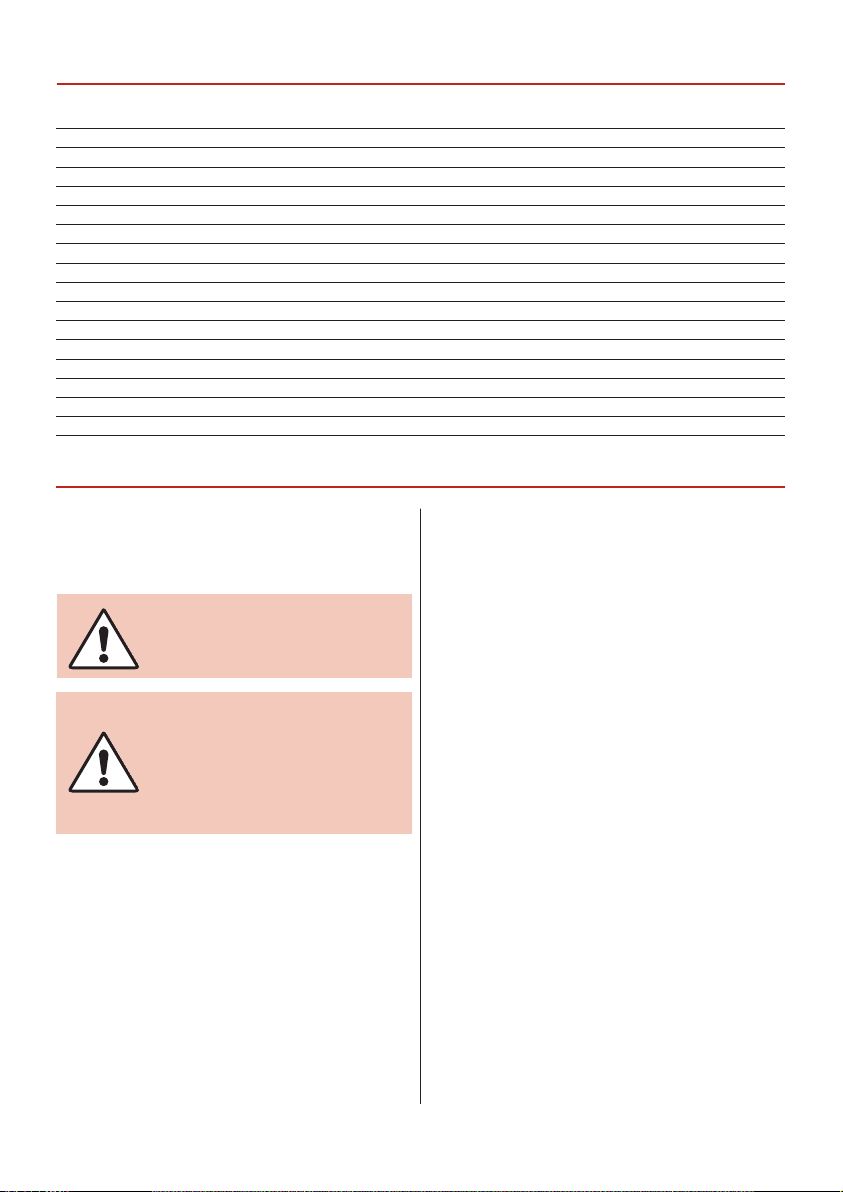
6. Always maintain a distance of 2mm or less between
the wheel and the tool rest. Adjust the tool rests as the
wheels decrease in size.
7. Ensure the tool rests are tightened so they cannot move
while in use.
8. Never grind on a cold wheel. The grinder should always
be run for at least one minute before applying work to it.
9. Never grind on the side of the wheel. Always grind on
the face of the wheel only.
10. Never apply coolant directly to a grinding wheel,
it may cause the bonding to fail. If the work piece
becomes hot, dip it into a water pot to cool it down.
11. Hot sparks are a hazard! Never carry out grinding
operations near flammable gas or liquid.
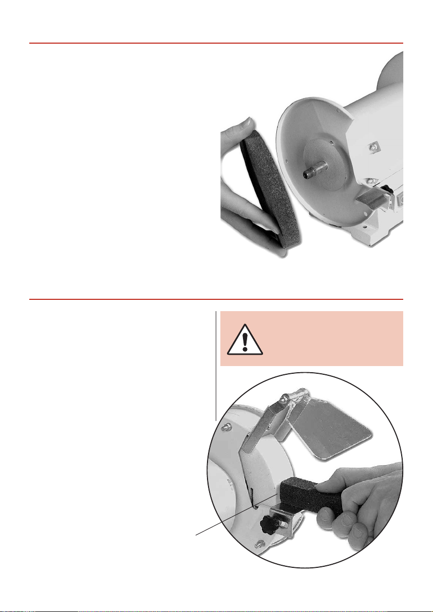
12. Always make sure the spark guards and eye shields are
in place, that they are properly adjusted and secured.
13. Keep the sparks guards close to the wheels and
re-adjust them as the wheels wear.
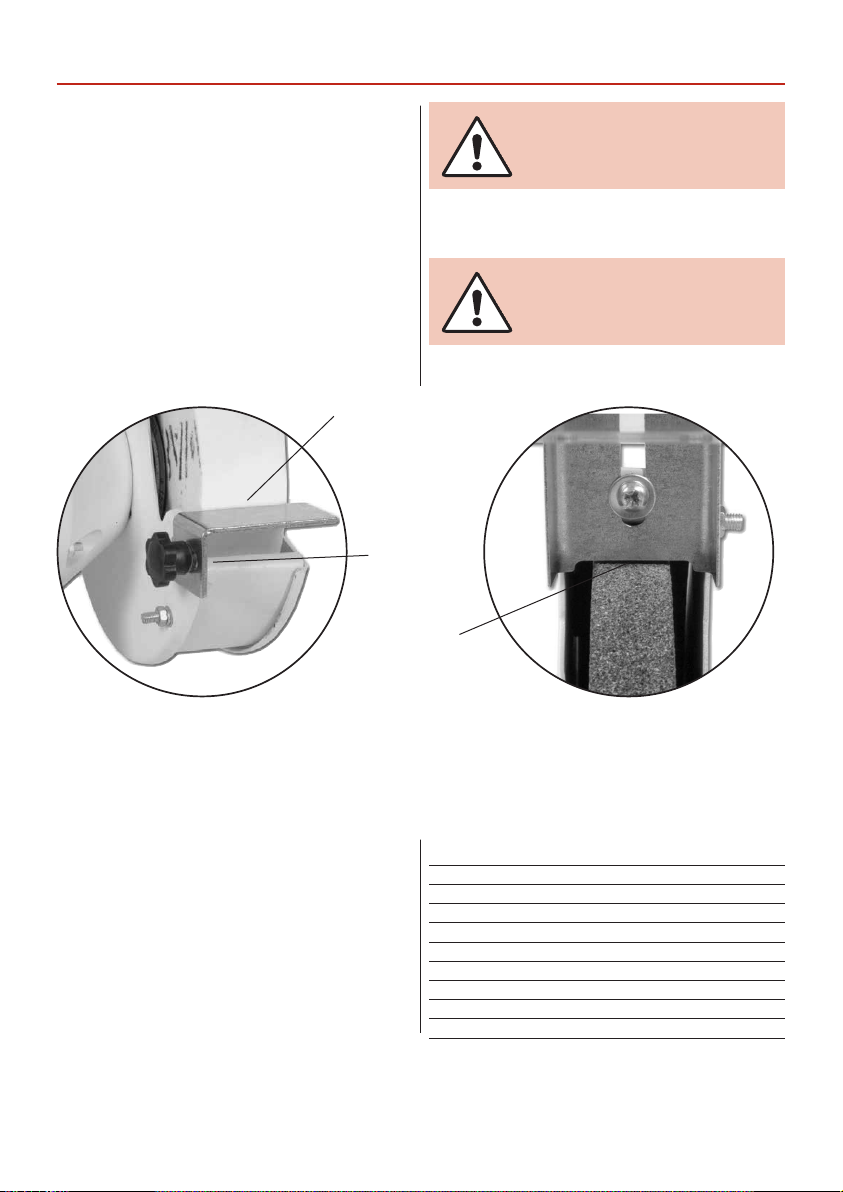
14. Ensure the soft washer and the flanges furnished
with the grinder, are used to mount any attachments
(grinding wheels, wire brushes, buffing wheels, etc)
onto the shaft.
15. Always stand to one side of the grinder when starting
the machine.
16. Avoid awkward hand positions where a sudden slip
could cause the hands to come into contact with a
grinding wheel, wire brush etc.
17. If the wheel requires dressing, dress only the front of
the wheel, do not dress the sides.
18. Do not use any attachments that causes the machine
to vibrate. If after changing grinding wheels or adding
attachments, the machine does vibrate; remove the
recently replaced item and change again.
19. Grinding creates heat. Do not touch the work face of
the work piece until you are sure it has cooled down
sufficiently.

8
Changing a Grinding Wheel
ENSURE THAT THE GRINDER IS
DISCONNECTED FROM THE MAINS
SUPPLY.
Undo the nuts and bolts that secure the outer shell of the
wheel guard to the inner shell. Remove the outer shell and
place it and the nuts, bolts and washers carefully aside.
(See fig 6)
BE VERY CAREFUL THAT THE STONE
COVER DOES NOT ‘SPRING’ OUT OF
ITS LOCATION LIP ON THE INNER
COVER, IT CAN SPRING OUT WITH
SOME FORCE. (SEE FIG 7)
Nut Plate flange
Fig 6. Fig 7.
Fig 8. Fig 9.
Loosen the nut holding the grinding wheel to the shaft. Carefully remove the nut, the plate flange and the soft washer
that is clamping the grindstone in place. (See figs 8 & 9) Then, very carefully remove the grindstone from the shaft, take
care that no damage or distortion is done to the bush (if one is fitted). (See fig 10) Now is a good time to clean out the
interior of the wheel guard, removing any loose or compacted material that may have accumulated. Carefully inspect the
new grinding wheel before it is fitted, check that there are no cracks, and there is no damage to either the front face or
the edges. If required, fit the bush to the grindstone. Carefully mount the grindstone onto the shaft, reposition the soft
washer and the wheel flange, replace the holding nut and tighten carefully. Do Not Overtighten. Refit the outside shell of
the wheel guard and secure with its nuts and bolts. Refit the tool rest, positioning as in “Setting up the grinder”. Fasten
securely.

9
Changing a Grinding Wheel
Dressing a Stone
Check that the spark guards and the tool rests are not
touching the grindstone. Reconnect the grinder to the
mains supply, give the grinder a ‘short burst’, by switching
it on and off quickly. Check the grinder is not subject to
any undue vibration. If the grinder does vibrate, strip it
down again and check that the bush (if fitted) is correctly
positioned and is the correct size for the stone and the
spindle. Check the bore of the stone is correct. If these all
seem correct, refit and carryout the ‘quick burst’ procedure
again. If the machine is still vibrating, discard the stone
and replace with another one. Run up to speed normally.
Leave the machine running for at least one minute before
carrying out any work. Apply a workpiece and check that
the spark guard is correctly positioned and that the tool
rest is securely fixed.
If necessary dress the new stone lightly to ensure a ‘good
face’ and good concentricity.
Fig 10.
If the grindstones wear unevenly, producing crests,
dips or rounded edges, they should be dressed out
using a suitable wheel dressing tool. (A selection of
stone dressing tools are available online. Please visit
axminster.co.uk.)
Switch the grinder on and allow it to run for at least one
minute. Rest the dressing tool on the tool rest and advance
it to the stone until it touches the maximum diameter;
gently move the dresser back and forth across the face of
the stone until all irregularities have been removed and
the edges of the stone are nice and sharp.
THIS IS NOT A PROCEDURE
THAT CAN BE RUSHED, IT MUST
BE CARRIED OUT SLOWLY AND
STEADILY.
Dressing the wheel
using a Wheel
Dressing Stick
Part No. 410074

10
Notes

11
Notes

Axminster Tools & Machinery Ltd
Axminster Devon EX13 5PH
axminster.co.uk
The packaging is suitable for recycling.
Please dispose of it in a responsible manner.
Do not dispose of electric tools together with household waste material.
By law they must be collected and recycled separately.
EU Countries Only
The Axminster guarantee is available on
Craft,Trade, Engineer, Air Tools & CNC Technology Series machines
Buy with confidence from Axminster!
So sure are we of the quality, we cover all parts and labour free of charge for three years!
For more information visit axminster.co.uk/3years
Table of contents
Other Axminster Craft Grinder manuals