Axminster Craft AC150SM User manual

Code 106178
Original Instructions
AT&M: 27/01/2020
BOOK REF : APT008074
BOOK VERSION: 1
AC150SM
Spindle Moulder

Index of Contents
2
The symbols below advise the correct safety procedures when using this machine.
Fully read manual
and safety instructions
before use
Eye protection
should be worn
Ear protection
should be worn
HAZARD
Dust mask
should be worn
Cert No: WS500F,
MX5111BF, MX5111BR
Axminster Tools & Machinery Ltd
Axminster Devon
EX13 5PH UK
axminster.co.uk
Type Spindle Moulder
Model AC150SM and conforms to the machinery example for which the
EC Type-Examination Certificate No AE 50390657
has been issued by Laizhou Planet Machinery Co., Ltd.
at:Yutai West Street, Laizhou, Shandong 261400, Shandong, China (Mainland)
and complies with the relevant essential health and safety requirements.
EN 61000-3-3:2013
EN 55014-1:2006+A1+A2
EN 55014-2:1997+A1+A2
EN 55014-1:2017
declares that the machinery described:-
This machine complies with the following directives:
EU Declaration of Conformity
EN 55014-2:2015
EN 61000-3-2:2014
Signed
Andrew Parkhouse
Operations Director Date: 15/12/2017
EU Declaration of Conformity
EU Declaration of Conformity 02
What’s Included 03
Optional Accessories 04
General Instructions for 230V Machines 04
Specific Safety Precautions 05
Specification 05
Assembly 06-07-08-09
Illustration & Parts Description 10-11-12-13
Positioning the Machine 14
Set Up and Adjustment
• Installing the Cutter Block 14-15-16-17
• Installing the Collet Adaptor 17-18
• Setting the Cast Iron Table 18
• Setting the Sliding Table 18-19
• Sliding Table Clearance 19
• Changing the Spindle Speed 19-20
Operating Instructions 21-22
Optional Accessories 22-23
Routine Maintenance 23
Trouble Shooting 24
Wiring Diagram 25
Exploded Diagrams/Lists 26-27-28-29
Notes 30-31

What’s Included
3
Quantity Item Part Model Number
AC150SM
1 Spindle Moulder (Main Body) A
1 Spindle Guard Assembly B
2 Spindle Guard Fences C
1 Guide Assembly Comprising: D
• Guide Arm
• Anti-kickback Plate
• Guide
1 Mitre Fence Work Clamp Assembly E
2 Side Panels & Front/Back Panels F
4 Lower Leg Columns G
1 Collet Adaptor H
2 Collets I
2 Insert Rings J
2 Collet Nuts (E0C12A-T22X1.5) K
1 22-24mm Spanner L
1 32mm Spanner M
2 M8 x 40mm Lift & Shift Handles N
1 5-6mm Hex Keys O
20 M8 Nuts P
20 M8 x 15mm Bolts Q
A
F
G
B
C
D
E
Front/Back
Panels
Side Panels
I
H
L
M
N
O
JK
P
Q

Optional Accessories
4
Quantity Item Part
1 AC150SM Bobbin Sander Attachment R Code: 106184
1 A150SM Bobbin Sander Abrasive SCode: 106185
R
S
General Instructions for 230V Machines
The following will enable you to observe good working
practices, keep yourself and fellow workers safe and maintain
your tools and equipment in good working order.
WARNING!! KEEP TOOLS AND EQUIPMENT
OUT OF REACH OF YOUNG CHILDREN
Mains Powered Tools
• Tools are supplied with an attached 16 Amp plug.
• Inspect the cable and plug to ensure that neither are
damaged. Repair if necessary by a suitably qualified person.
• Do not use when or where it is liable to get wet.
Workplace
• Do not use 230V a.c. powered tools anywhere
within a site area that is flooded.
• Keep machine clean.
• Leave machine unplugged until work is about to commence.
• Always disconnect by pulling on the plug body and not the
cable.
•Carry out a final check e.g. check the cutting tool
is securely tightened in the machine and the correct
speed and function set.
•Ensure you are comfortable before you start work,
balanced, not reaching etc.
•Wear appropriate safety clothing, goggles, gloves,
masks etc.Wear ear defenders at all times.
•If you have long hair wear a hair net or helmet to prevent it
being caught up in the rotating parts of the machine.
•Consideration should be given to the removal of rings and
wristwatches.
•Consideration should also be given to non-slip footwear etc.
•If another person is to use the machine, ensure they are
suitably qualified to use it.
•Do not use the machine if you are tired or distracted.
•Do not use this machine within the designated safety areas
of flammable liquid stores or in areas where there may be
volatile gases.
•Check cutters are correct type and size, are undamaged
and are kept clean and sharp, this will maintain their
operating performance and lessen the loading on the
machine.
•OBSERVE…. make sure you know what is happening
around you and USE YOUR COMMON SENSE.
KEEP WORK AREA AS UNCLUTTERED AS IS PRACTICAL.
UNDER NO CIRCUMSTANCES SHOULD CHILDREN BE
ALLOWED IN WORK AREAS.
See the full range of ‘Axcaliber Euro Cutter Heads’ in our
catalogue and on our web site at ‘axminster.co.uk’

Specific Safety Precautions
5
This machine is designed for shaping wood and wood derived
materials.
• Machining of other materials is not permitted and may be
carried out in specific cases only after consulting with the
manufacturer.
• The proper use also includes compliance with the operating
and maintenance instructions given in this manual
• The machine must be operated only by persons familiar with
its operation and maintenance and who are familiar with its
hazards.
• The required minimum age must be observed.
• The machine must only be used in a technically perfect
condition.
• When working on the machine, all safety mechanisms and
covers must be in operation.
• In addition to the safety requirements contained in these
operating instructions and your country’s applicable
regulations, you should observe the generally recognized
technical rules concerning the operation of woodworking
machines.
• Any other use exceeds authorisation.
• In the event of unauthorised use of the machine, the
manufacturer renounces all liability and the responsibility
is transferred exclusively to the operator.
• Woodworking machines can be dangerous if not used
properly.Therefore the appropriate general technical rules as
well as the following notes must be observed.
• Read and understand the entire instruction manual before
attempting assembly or operation.
• Keep these operating instructions close by the machine,
protected from dirt and humidity, and pass them over to the
new owner if you part with the tool.
• No changes to the machine may be made.
• Daily inspect the function and existence of the safety
appliances before you start the machine. Remove all loose
clothing and enclose long hair.
• Before operating the machine, remove tie, rings, watches,
other jewellery, and roll up sleeves above elbows.
• Wear safety shoes; never wear leisure shoes or sandals.
• Always wear the approved working outfit.
• Do not wear gloves while operating the machine.
• For the safe handling of cutting tools wear work gloves.
• Control the stopping time of the machine, it may not
exceed 10 seconds.
• Remove cut and jammed work pieces only when the
machine is at a complete standstill and motor is turned off.
• Install the machine so that there is sufficient space for safe
operation and work piece handling.
• Keep work area well lit.
Authorised Use General Safety Notes
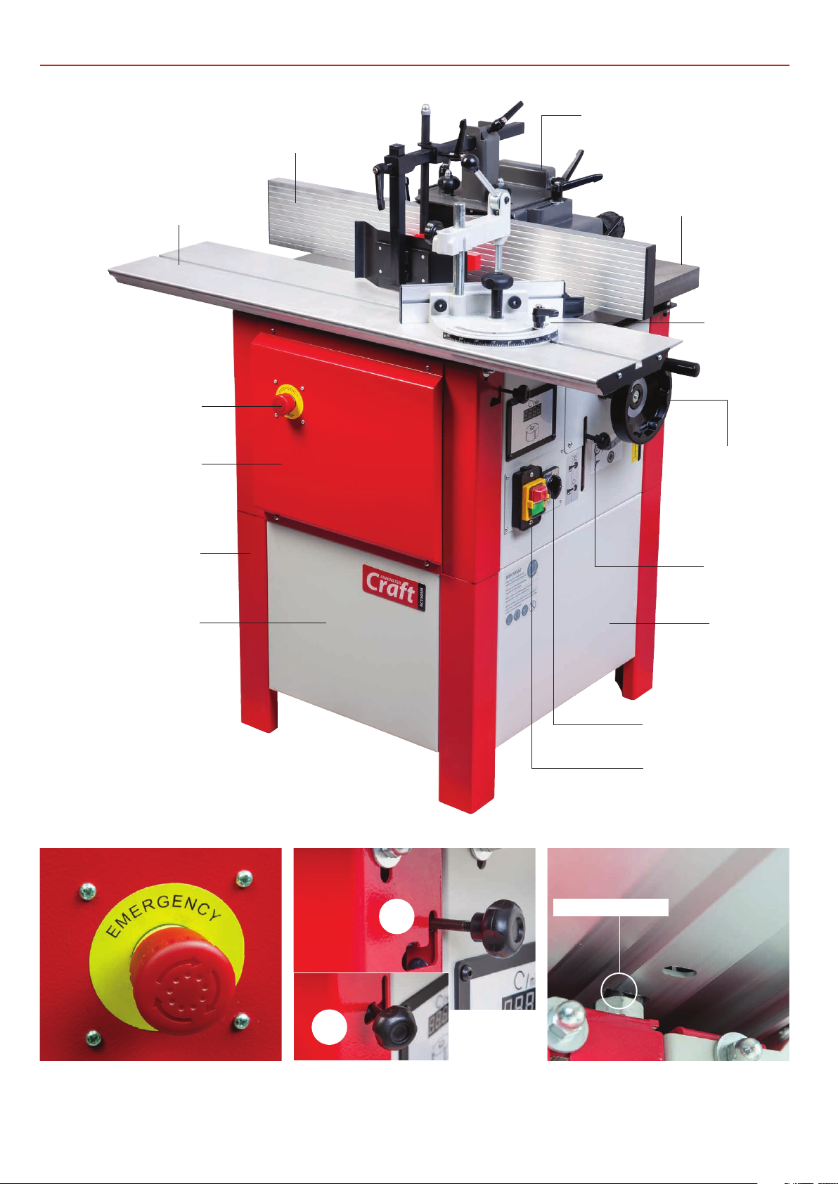
Specification
Code 106178
Model AC150SM
Rating Craft
Power 1.5 kW
Spindle Travel 105 mm
Spindle Diameter 30 mm
Spindle Speed 1,400, 4000, 6000, & 8,000 rpm
Sound Power Level [Uncertainty K] 68 dB(A)
Max Spindle Projection above Table 100 mm
Max Tooling Diameter Above Table 140 mm
Max Tooling Diameter Below Table 140 mm
Table Height 800 mm
Table Size 600 x 400 mm
Min Extraction Airflow Required 1,200 m³/hr
Dust Extraction Outlet 100 mm
Overall L x W x H 660 mm x 1,000 mm x 1,100 mm
Weight 100kg

Assembly
6
3
2
1
7
6
5
4
PLEASE NOTE: FOR YOUR OWN SAFETY IT
IS REQUIRED THAT TWO PEOPLE ASSEMBLE
THIS MACHINE!
Unpack all the boxes and check all the components against
the ‘What’s in Included’ list. If any parts or components are
missing, please contact our customer services department
using the procedures and telephone numbers listed on our
website, and you will be dealt with quickly and efficiently.
Having unpacked the boxes, (please dispose of any
unwanted packaging responsibly), put the parts and
components whereby they are readily to hand. Break down
the main box by knocking the sides away (be careful of
exposed nails etc.), but leave the machine sitting on its
pallet. Remove the protective grease film that is coating
all the unpainted parts of the machine.
Leg Assembly
Remove the motor door lift & shift handle to prevent it from
being damaged when the machine is turned on its side.
Secure the front and back panels as shown in fig 7.
Locate the four lower leg columns (G), M8 bolts & washer (P)
and nuts (Q). Mount the legs to each corner of the machine’s
base and secure in position. NOTE: Make sure the two holes on
the side of each leg are in the upward position as shown in fig 4.
Mounting
holes
G
F
Panel mounting holes
Front/back
panels

Assembly
7
10
11
8
9
3
2
1
12
Spindle Guard Assembly
Tighten all the fixings and with assistance place the spindle
moulder on its feet, see fig 10-11. Replace the door handle.
Secure the side panels as shown in fig 8-9.
Locate the spindle guard (B), spindle guard fences (C) and two
lift & shift handles/washers (N).
B
N
C
N
Mounting holes
Side
panels
Continues over...

Assembly
8
7
6
5
4
11
9
10
8
C
The fence is a two piece adjusting system.
Each fence is independently adjustable to
compensate for different cutting thick-
nesses. Place a steel straight edge across
both fences (C), loosen the fence advance
clamping handle (a) and adjust the fence
advancing knob/s (b). Adjust until both
are aligned, see fig 7. Nip-up the clamping
handle (a) to lock the setting.
Fence
clamping
knob
Slide the
fence over
the ‘T’ bolt
a
b
Make sure the fence is square to the work surface, place a 90°
square up against the fence and check it is perpendicular to
the work surface. If adjustment is required adjust the four grub
screws to the rear of the fence mounting plates, see fig 8.This
pivots the fence forward and aft. Adjust until correct, see fig
9-10.
Locate the guide assembly (D).Insert the guide arm through
the guide arm mounting bracket on the spindle guard
assembly (B). Note: align the guide arm angle bracket between
the mounting bracket and nip-up the clamping handle (c), see
fig 11-12-13-14.
Guide Assembly
D
Angle bracket
Grubscrew
Fence
Mounting Plate
Grub screws

Assembly
9
15
14
13
12
19
18
17
16
Mitre Fence Assembly
E
Table ‘T’ slot
Angle bracket
Square
Pointer Adjusting
screw
Mounting bracket
Locate the Mitre fence work clamp (E) and slide it into the
sliding tables ‘‘T’ slot, see fig 15. Using an engineers square, set
the mitre fence at 90˚ degrees to the spindle guard fence (C).,
see fig 16. Check the scale pointer is set to ‘zero’ and adjust if
necessarily. Tighten both the clamping knob and handle, see fig
17-18.
C

Illustration & Parts Description
10
Emergency stop
Twist clockwise to unlock
Sliding table locking lever in the locked position (A)
Lever in the unlocked position (B)
Sliding table
Access panel
Leg column
Front panel Side panel
Work table
Emergency stop button
Mitre fence &
work clamp
Fence
ON/OFF Control switch
Spindle control switch
Spindle lock
Spindle guard assembly
Spindle height
control wheel
Front View
B
A
Table locking slot

Illustration & Parts Description
11
Motor/Spindle assembly height locking knob Motor and spindle access door
Rear panel
Air vents
Work clamp lever
Window
Locking handle
Motor access door
Work table height
assembly
Rear View

Illustration & Parts Description
12
Anti-kickback clamp
Work guide
Anti-kickback
steel plate
Fence advancing
clamping handle
Spindle guard lid
locking knob
Fence adjusting knob
Fence advancing
control knob
Dust extraction outlet
Spindle guard clamp
Spindle guard hinged
lid locking handle
Work guide
clamping handle
Guide assembly locking handle
Mitre fence tilt
clamping handle
Mitre fence clamping knob
Clamp height locking knob

Illustration & Parts Description
13
ON/OFF control switch (A), Spindle control switch (B) Spindle height scale/pointer
Turn the spindle & press in the
locking knob to lock the spindle
Cutter block speed D.R.O.‘Digital Read Out’
Mitre fence/ work clamp assembly Spindle rise and fall control wheel (A)
Control wheel locking handle (B)
BA
A
B
(R) Clockwise
direction
OFF
(L) Anti-clockwise
direction

Positioning the Machine
14
Ascertain the orientation of the machine and move it to its
desired position in the workshop. Ensure that the machine is
positioned to allow sufficient clearance all round to cater for
the maximum length of timber you wish to machine.
The machine should be positioned on a flat level surface.
Manoeuvre the machine to the chosen location, then carefully
lower the machine down.
THE SPINDLE MOULDER IS A HEAVY
PIECE OF EQUIPMENT.YOU ARE
ADVISED TO SEEK HELP OR THE USE
OF SOME FORM OF LIFTING DEVICE,
(HOIST, ENGINE CRANE) BEFORE YOU
ATTEMPT TO LIFT OR MOVE THIS
MACHINE.
Set Up and Adjustment
1
2
4
3
Loosen the two locking knobs to either side spindle guard lid
and raise the lid. Nip-up the lid locking handle, see fig 4-5-6.
Raise the spindle to its maximum height by unlocking the
rise/fall control wheel locking handle and the locking knob
to the rear of the machine see fig 1-2.Turn the control wheel
clockwise to raise the spindle, see fig 3.
See the full range of ‘Axcaliber Euro Cutter Heads’ in our
catalogue and on our web site at ‘axminster.co.uk’
MAKE SURE THE MACHINE IS
DISCONNECTED FROM THE MAINS!
Installing the Cutter Block
Unlock

Set Up and Adjustment
15
7
8
10
11
6
59
Using the supplied 24mm spanner (L), remove the bolt (a)
and clamping block (b) from the spindle. Place safely aside
the spacer collars (c) and shims (d), see fig 10-11.
NOTE: Removing the insert rig from the arbor, see fig 12
may depend on what size of cutter block is being used and
what your machining. Introduce a spacer collar (c) down over
the arbor, see fig 13 on page 16.
Turn the spindle by hand and press the spindle lock rod in,
until the lock engages into the spindle’s machined hole.Thus
locking the spindle in place, see fig 7-8.
Lock handle
b
a
d
c
NOTE:THE MACHINE WILL NOT
START WITH THE SPINDLE LOCK
ENGAGED, SEE FIG 9!
Spindle lock micro switch prevents the machine from starting
accidentally, avoiding damage to the spindle mechanism.
Spindle lock
Continues over...
CLEAN ALL SURFACES OF SPINDLE
ARBOR BEFORE MOUNTING THE
CUTTER BLOCK.
12
L

Set Up and Adjustment
16
18
19
19
21
20
Cutter block
The base of the lower
blade tip should sit just
below the suface of the
table
Spacer collars & shims
14
16
17
15
Lower the cutter block down over the spindle arbor making
sure the description of the block is on top, see fig 14-15.
Replace the bolt (a) and tighten using the 24mm spanner.
Adjust the fences as close to the cutter block as possible but
not too close that it come into contact with the cutter.
Fence
Fence
Cutter block
Spacer collar
13
Lower the camping block
(b) down on top spindle
arbor making sure the
locating pin slots into the
keyway in the spindle.
Clamping
block
Keyway
Spacer collar
Shims
Locating pin
WEAR GLOVES WHEN CHANGING
OR REPLACING THE BLADES!
b
a

Set Up and Adjustment
17
23
24
22
Move the control select switch to the ‘R’ (Clockwise Direction),
see fig 24. Give the machine a‘quick’ burst check (i.e. quick ON-
OFF) to ensure everything is O.K. If everything is satisfactory,
switch off the machine and wait until it has come to a complete
stop.
Close the spindle guard lid and re-secure. Release the spindle
by pulling out the locking rod, see fig 23.
Installing the Collet Adaptor
REMOVE ALL TOOLS AWAY FROM
WORK AREA!
CONNECT THE MACHINE TO THE
MAINS SUPPLY!
DISCONNECT THE MACHINE FROM
THE MAINS SUPPLY!
A GENTLE PULL IS SUFFICIENT!
The spindle moulder can be converted into a router table by
fitting the ‘Collet Adaptor’ (H), see fig 1.
1
2
3
H
Press in the spindle lock.Remove the spindle arbor by
removing the centre Hex screw, see fig 2. Place to one side.
Use a soft mallet and tap the arbor top to release the vacuum
on the taper.
Hex key
I
K
4
Locating pin
Locating hole
Spindle cone
H
Continues over...
H

Set Up and Adjustment
18
5
9
8
7
6
1
2
10
Line up the locating pin with the hole to the base of the collet
adaptor and insert the adaptor (H) onto the spindle cone.
Replace the Hex screw and tighten. Insert the collet (I) and
screw on the collet nut (K), see fig 3-4-5-6-7-8-9-10.
The cast iron table can be adjusted by the two height bolts/
nuts, beneath the table.Two to each side, see fig 1. Place a level
on the table and adjust the bolts if required, see fig 2-3.
The sliding table needs to be set about 0.5mm above the main
table. If adjustment is required adjust the two domed head nuts
to two each side of the table, see fig 4-5.
Collet
Collet nut
H
I
K
Setting the Cast Iron Table
Setting the Sliding Table
Modern cutters have a safe hold (K) line and a maximum
running speed engraved upon the shank as a general
guide.
3
Safe hold ‘K’ Line

Set Up and Adjustment
19
8
6
7
4
5
1
10
9
Another method is to adjust the guide rollers beneath the
sliding table. First remove the access panel and place carefully
to one side, see fig 6-7.
Inside and above are two threaded nuts, see fig 8. Adjust the
nuts to raise or lower guide rollers, see fig 9.
Once completed replace the access panel.
0.5mm
Guide roller
Feeler gauge
CHECK THE TABLE IS STILLSQUARE
TO THE FENCE AND MAKE
ADJUSTMENTS IF REQUIRED!
Changing the Spindle Speed
Sliding Table Clearance
DISCONNECT THE MACHINE FROM
THE MAINS SUPPLY!
Open the motor access door to the side of the machine, see fig
1-2. Lower the spindle to its lowest point, if not done so already.
Adjust the two domed head nuts to two each side of the table,
see fig 5. Slot the feeler gauge down the gap between
the two tables from one side and adjust until the gap is set
between (0.5 to 2mm), repeat the procedure for the opposite
side, see fig 10.
Continues over...

Set Up and Adjustment
20
3
24
Loosen the locking handle (A) beneath the motor and
pivot the motor to the right using the operating lever (B).
Using the ‘Spindle Chart’ above and ‘Cutter Block Speed
Chart’ below reposition the ‘V’ belt to the appropriate
speed required. Make sure the grooves in the belt set
correctly in the pulley grooves. Push the motor back to
retention the belt.Tighten the locking handle to secure
the setting, see fig 3-4.
A
B
Spindle
Motor
‘V’ Belt
Cutter Block Speed Chart
Spindle Chart
Cutter Block Diameter (mm)
Spindle Speed (RPM)
1,400
RPM
Spindle
4,000
6,000
8,000
Motor
Table of contents
Other Axminster Craft Industrial Equipment manuals