10
Assembly Instructions
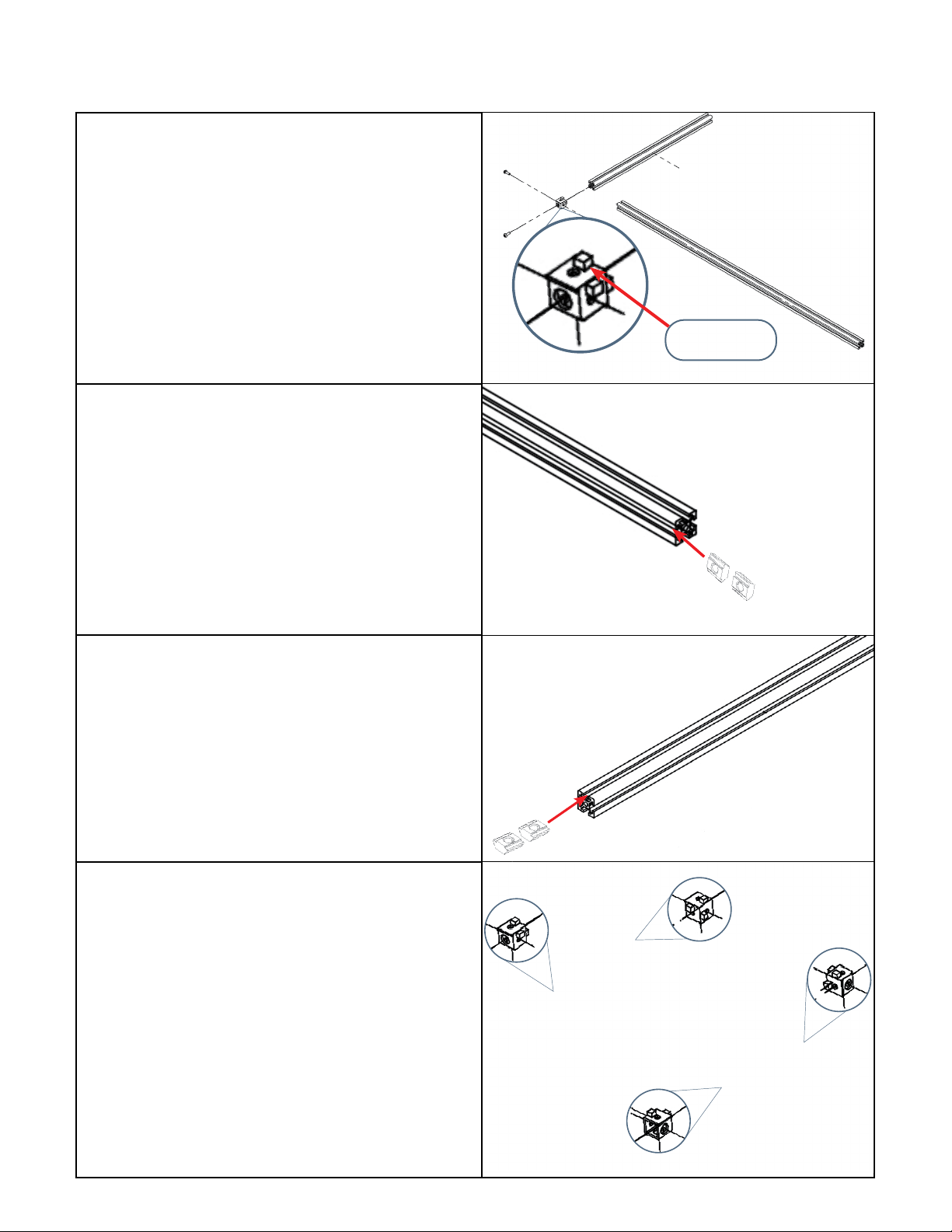
Bottom Frame Assembly
Step 1. Connect one S frame to one L frame
with an aluminum frame corner bracket and
(2) x I bolts to make one half of the bottom
frame.
Step 2. Connect another S frame to another L
frame with an aluminum frame corner bracket
and (2) x I bolts to make the other half of the
bottom frame.
Tool Required:
4 mm Allen key
Step 3. Slide two pre-assembly insertion short
nuts into the outer groove of each L frame (four
nuts total).
Step 4. Slide two pre-assembly insertion
short nuts into the top groove of one of the S
frames.
Note: The magnetic switch for the front door
will be attached to this S frame.
Step 5. Attach two aluminum frame corner
brackets to the other ends of the S frames
with (2) x I bolts to secure the pre-assembly
insertion short nuts inside the aluminum
frames.
Step 6. Connect one half of the bottom frame to
the other half with (2) x I bolts.
Note: Please refer to the drawing on page 24
for a larger exploded view of the bottom frame.
Tool Required:
4 mm Allen key
Ensure that the rivet is
facing upwards.