ABB CC1600-SC55 User manual

Page 1
© 2023 ABB. All rights reserved. CC1600SC55_QSG Rev 4.0
CC1600-SC55 Small Cell -48V Power Source
Document – 8600190737P
QUICK START GUIDE

Page 2
© 2023 ABB. All rights reserved. CC1600SC55_QSG Rev 4.0
Important Safety Instructions ........................................................................................................................3
Precautions ........................................................................................................................................................4
Introduction .......................................................................................................................................................5
Installation..........................................................................................................................................................5
1. Prepare a Location and mounting option for the Small Cell -48V Power Source
w/ Shield Base Option. 1...................................................................................................................5
2. Mount the Solar Shield Base w/ Solar Shield Base Option 1 ......................................................5
3. Prepare a Location & mounting for the Small Cell -48V Power Source
w/ Five (5”) Elevation Option. 2.......................................................................................................7
4. Mount the Base Rectifier .................................................................................................................8
5. Ground the Rectifier ..........................................................................................................................8
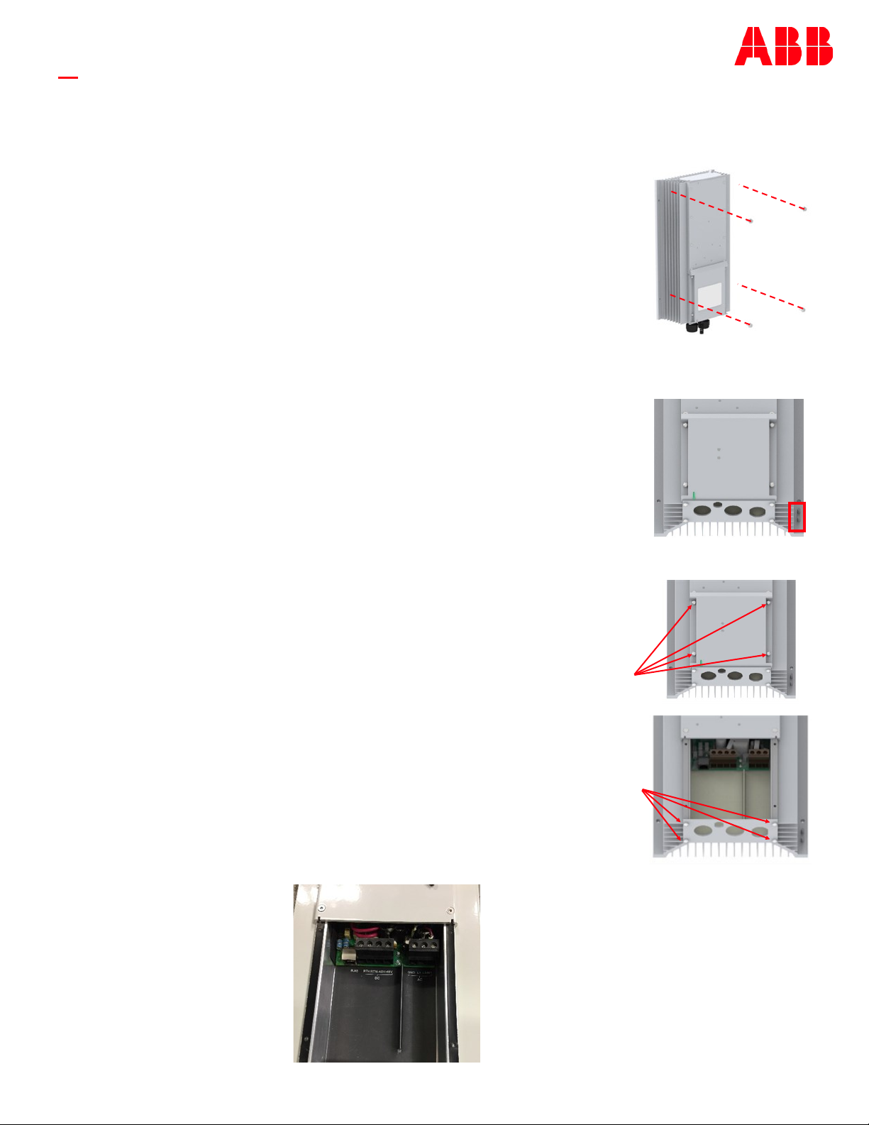
6. Open the Field Wiring Compartment .............................................................................................8
7. Wire the DC Output with Panel Option #1 .....................................................................................9
8. Wire the DC Output with Panel Option #2.....................................................................................10
9. Wire the Alarms ..................................................................................................................................11
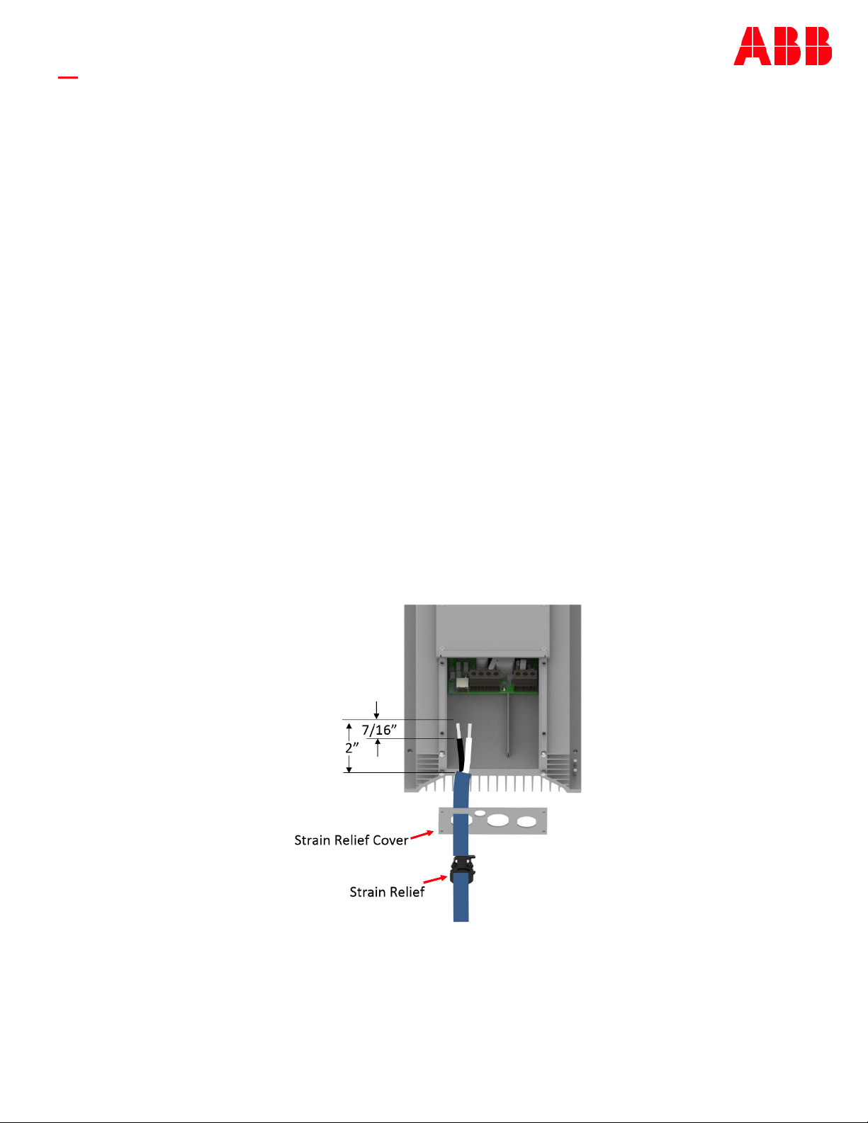
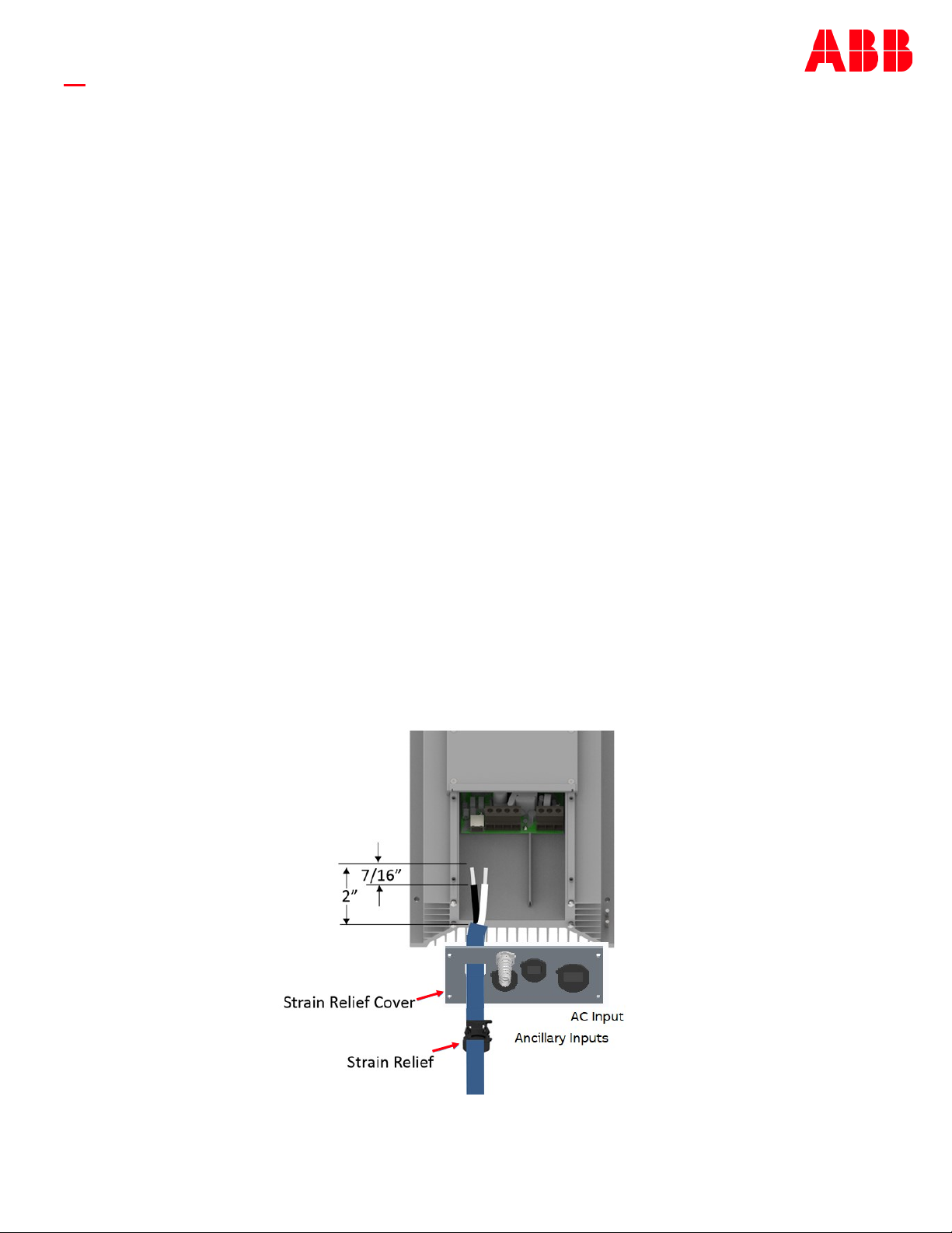
10. Wire the AC Input ...............................................................................................................................11
11. Close the Field Wiring Compartment.............................................................................................12
12. Apply AC Power and Confirm -48V Power Delivery ......................................................................13
13. Attach the Solar Shield Cover for Solar Option 1..........................................................................13
14. Attach the Solar Shield Cover for Solar Option 2..........................................................................14
Information:
Electrical Connections................................................................................................................................14
LED States ....................................................................................................................................................14
Pole Mount Bracket Detail for Option 1...................................................................................................16
Pole Mount Bracket Detail for Option 2...................................................................................................17
Parts List.............................................................................................................................................................18
Specifications & Application ...........................................................................................................................18
Reference Documents ......................................................................................................................................18
Contents

Page 3
© 2023 ABB. All rights reserved. CC1600SC55_QSG Rev 4.0
Important Safety Instructions
1. SAVE THESE INSTRUCTIONS – This document contains important safety and operating instructions for the Small Cell 48V
Power Source.
2. Before using the Small Cell 48V Power Source, read all instructions and cautionary markings on the AC Panel Feeding the
unit, the radio, and all other connected equipment.
3. Rules and Regulations - Follow all national and local rules and regulations when making field connections.
4. Field-wired Conductors - Follow all National Electric Code (NEC) and local rules and regulations.
a. Insulation rating: 90°C minimum; 105°C (minimum) if internal to enclosed equipment cabinets.
b. Size AC field-wired conductors with 75°C ampacity (NEC) equal to or greater than their panel board circuit breaker
rating.
c. Size DC field-wired conductors with 90°C ampacity (NEC) equal to or greater than 30A .
5. AC input disconnect/protection - Provide accessible devices to remove input power in an emergency.
6. Compression Connectors
a. U. S. or Canada installations - use Listed/Certified compression connectors to terminate Listed/Certified field-wire
conductors.
b. All installations - apply the appropriate connector to the correct size conductor as specified by the connector
manufacturer, using only the connector manufacturer’s recommended or approved tooling for that connector.
7. Electrical Connection Securing: Torque to the values specified on labels or in the product documentation.
8. Cable Dress - dress to avoid damage to the conductors and undue stress on the connectors. Always provide a drip loop to
shed water off cables before they enter the strain reliefs.
9. Alarm Signals - Provide external current limiting protection. Rating–60V (125V for 125V charger), 0.5A unless otherwise
noted.
10. Grounding - Connect the equipment chassis directly to ground.
11. This equipment is to be mounted directly and permanently above non-combustible surface, such as concrete or metal.
12. WARNING: Equipment is not designed to charge an external battery source.
13. WARNING: A battery can present a risk of electrical shock, burn from high short circuit current, fire or explosion from vented
gases. Observe proper precautions.

Page 4
© 2023 ABB. All rights reserved. CC1600SC55_QSG Rev 4.0
Precautions
• Install, service, and operate equipment only by professional, skilled and qualified personnel who have the necessary
knowledge and practical experience with electrical equipment and who understand the hazards that can arise when
working on this type of equipment.
• Do not disconnect permanent bonding connections unless all power inputs are disconnected.
• Verify that equipment is properly safety earth grounded before connecting power. High leakage currents may be possible.
• Exercise care and follow all safety warnings and practices when servicing this equipment. Hazardous energy and voltages
are present in the unit and on the interface cables and connectors that can shock or cause serious injury.
• Use safe lifting practices. The equipment is heavy. Lifting devices are recommended.
• Use the following precautions in addition to proper job training and safety procedures:
• Use only properly insulated tools.
• Remove all metallic objects (key chains, glasses, rings, watches, or other jewelry).
• Follow Lock Out Tag Out (LOTO) procedures: customer specified, site specific, or general as appropriate.
Disconnect all power input before servicing the equipment. Check for multiple power inputs.
• Wear safety glasses.
• Follow Personal Protective Equipment requirements: customer specified, site specific, or general as appropriate.
• Test circuits before touching.
• Be aware of potential hazards before servicing equipment.
• Identify exposed hazardous electrical potentials on connectors, wiring, etc.
• Avoid contacting circuits when removing or replacing covers;
• Use a personal ESD strap when accessing or removing electronic components.
• Follow all warning and precautionary battery instructions, including proper replacement and disposal procedures, to
minimize risk of injury.
• Personnel with electronic medical devices need to be aware that proximity to DC power and distribution systems can affect
medical electronic devices, such as pacemakers. Effects decrease with distance.

Page 5
© 2023 ABB. All rights reserved. CC1600SC55_QSG Rev 4.0
Installation
Regulations, standards, site engineering instructions, MOPs, etc. take precedence over these general installation
instructions.
• Steel toed safety shoes • Torque wrench - 0-65 in-lb (0-10
Nm) and 40 ft-lbs
• Sockets - as needed for mounting
hardware
• Wire cutters, strippers,
Termination & Channel Lock
Tools
• Volt Meter for Lock-Out Tag-Out
procedures.
• Screwdrivers - #2 pozi drive screwdriver.
Flat and Torx bit set with security pin
Tools required:
Step 1 – Prepare a Location and mounting option for the Small Cell -48V Power
Source w/ Shield Base Opt. 1
The unit can mount to a pole, to a wall with solar shield, or to location shaded from the sun. Step 1 is preparing the
foundation to receive either a solar shield, or the bare Small Cell -48V Power source.
When choosing a location for the Small Cell -48V Power Source, please keep in mind:
1. The rectifier must be mounted in “portrait” orientation so that air can flow vertically by natural convection.
2. Leave 3 inches above and below the unit to allow air to feed the fins and exit from the fins.
3. If the mounting location has sun exposure, a solar shield or cabinet must be used to protect the unit from
direct sun.
4. Mount the unit above the flood line. Weep holes to equalize pressure and drain any water/condensate that
may enter.
5. Orient the wiring entrance toward the ground and provide drip loops to shed any water running down the
jacket.
Introduction:
The Small Cell -48V Power Source provides -48Vdc power to next generation radios used in small cell sites. It
delivers 1200 Watts of DC Power from 120Vac source, or 1600 Watts of DC power from a 208-240Vac source.
Basic Features:
One DC output can be wired to 2 different devices. The positive voltage is referenced to ground. The output is -48V
nominal. It can be powered off of either 120Vac or 208-240Vac with operational parameters as shown here:
Input: 11.5 A @ 120Vac, Output: 21.8A @55Vdc / 1200 W Maximum.
Read and follow all safety statements, warnings, and precautions in this guide.

Page 6
© 2023 ABB. All rights reserved. CC1600SC55_QSG Rev 4.0
p/o Step 1 – Pole Locations For use with Solar Shield Option 1
A. Remove the pole mount bracket from the packaging.
B. Select an elevation and orientation on the pole. Note: Wires must dress out of the
bottom of the unit when installed. Use the bracket as a template to locate holes. 2
primary holes are on 10 inch centers.
C. Use 1/2 inch diameter hardware, 1.25 inch wide straps or 1/2 inch threaded rod to
attach the pole mount bracket to the pole. Torque lag bolts as specified on the bolt
corresponding to the pilot hole and material of the pole. Torque hdwr on 1/2 inch
threaded rod to 38 ft-lbs.
p/o Step 1 – Wall Locations For Use with Solar Shield Option 1
A. Remove the Solar Shield Cover and Solar Shield Base from the packaging. Put the
cover aside, or back into the packaging , to save for a later step.
B. Select a location for the Small Cell Power Source. Location should be above highest
recorded flood level. Note: Bracket must be mounted in “Portrait” orientation with
the shelf on the bottom edge, as shown here.
C. Drill holes to accept four 1/4” fasteners. Use the Solar Shield Base as a template.
Vertical hole centers are 15.6 inches apart. Horizontal hole centers are 10.4 inches
apart.
p/o Step 1 Wall Mount Shaded Locations
(With Shield Base Option 1)
A. Remove the Base Rectifier from the packaging.
B. Select a location for the Small Cell Power Source. Location should be above highest recorded flood level.
Note: Unit must be mounted in “Portrait” orientation with the wires at the bottom.
C. Drill holes to accept four 1/4” fasteners. Use the Base Rectifier as a template. Vertical hole centers are 12
inches apart. Horizontal hole centers are 8.87 (8 and 7/8 ) inches apart.
If a Solar Shield is called for, mount the Solar Shield Base to the four 1/4-20 holes in the
pole mount bracket, or the prepared holes in the wall prepared in Step 1. Torque bolts
as recommended by the wall anchor manufacturer, or to 65 in-lbs. if using the pole
mount bracket.
CAUTION: Use safe lifting practices. Lifting devices are recommended. Steel toed
shoes required.
The wall and fasteners must safely support 90 lbs. (3 times the weight of the
completed assembly).
Mount with 4 fasteners rated for at least 50 lbs. each
Step 2 – Mount the Solar Shield Base w/ Solar Shield Base Option 1

Page 7
© 2023 ABB. All rights reserved. CC1600SC55_QSG Rev 4.0
Step 3 – Prepare a Location & mounting for the Small Cell -48V Power Source
w/Five (5”) Elevation Option. 2
The unit can mount to a pole, to a wall with solar shield, or to location shaded from the sun. Step 3 is preparing
the foundation to receive either a solar shield, or the bare Small Cell -48V Power source.
When choosing a location for the Small Cell -48V Power Source, please keep in mind:
1. The rectifier must be mounted in “portrait” orientation so that air can flow vertically by natural convection.
2. Leave 3 inches above and below the unit to allow air to feed the fins and exit from the fins.
3. If the mounting location has sun exposure, a solar shield or cabinet must be used to protect the unit from
direct sun.
4. Mount the unit above the flood line. Weep holes to equalize pressure and drain any water/condensate that
may enter.
5. Orient the wiring entrance toward the ground and provide drip loops to shed any water running down the
jacket.
p/o Pole or Wall Locations For Five (5”) Elevation Bracket
(For Use with Solar Shield Option 2)
A. Remove the 5” Elevation bracket from the packaging.
B. Select an elevation and orientation on the pole. Note: Wires must dress out of the
bottom of the unit when installed. Use the bracket as a template to locate holes. 2
primary holes are on 13” inch centers.
C. Use 1/2 inch diameter hardware or 1/2 inch threaded rod to attach the pole mount
bracket to the pole. Torque lag bolts as specified on the bolt corresponding to the
pilot hole and material of the pole. Torque hardware on 1/2 inch threaded rod to 38
ft-lbs.
Wall or Pole Mount (in Shaded Location)
Five (5”) Elevation Bracket Option #2
A. Follow Steps A and B from above.
B. Use 1/2 inch diameter hardware or 1/2 inch threaded rod to attach the pole mount bracket to the pole. Torque
lag bolts as specified on the bolt corresponding to the pilot hole and material of the pole. Torque hardware on
1/2 inch threaded rod to 38 ft-lbs.

Page 8
© 2023 ABB. All rights reserved. CC1600SC55_QSG Rev 4.0
Step 4 – Mount the Base Rectifier
CAUTION: Use safe lifting practices. The Base Rectifier is heavy at 25 lbs. Steel toed
shoes are required. Lifting devices are recommended for elevated
applications.
1. If mounting to a wall, hold the rectifier so that the holes line up. If using the
Solar Shield kit, place the rectifier on the “shelf of the solar shield base” so that
the 4 holes for 1/4 inch hardware line up.
2. Use a 1/4 inch fastener to secure the Base Rectifier to the Solar Shield Wall or
Base.
3. Torque each of the 4 bolts as recommended by the wall anchor manufacturer,
or to 65 in-lbs. if using the Solar Shield.
Step 5 – Ground the Rectifier
There are #10-32 studs on 5/8 centers on the lower right corner of the rectifier. Use
this location to provide external grounding as required by code or network standard.
8 AWG minimum recommended ground wire.
Torque each nut to 26 in-lbs.
Step 6 – Open the Field Wiring Compartment
The field wiring compartment is located on the lower third of the unit. The front
cover is secured by 4 captive screws. The bottom cover that provides strain relief is
also secured by 4 captive screws.
1. Use a slotted screwdriver, or Torx security pin bit, to loosen each of the 4 captive
screws on the front face of the wiring cover.
2. Once all four screws are loose, remove the wiring cover. Wiring chamber will look
like this.
3. Use a slotted screwdriver, or Torx security pin bit, to loosen each of the 4 captive
screws on the face of the bottom cover.
4. Once all four screws are loose, remove the bottom cover that provides strain
relief.
The Field Wiring Compartment should now look like figure below.

Page 9
© 2023 ABB. All rights reserved. CC1600SC55_QSG Rev 4.0
Step 7 – Wire the DC Output Option #1
Two DC Output, One AC Input, Alarms
This rectifier configuration will accept up to 2 pairs of 8 AWG Wire in the terminal block located on the left side of
the wiring space. Select a wire and jacket suitable for the application. The DC strain relief hole is a 3/4” trade size
hole. If the supplied strain relief does not work with the wire selected, use a strain relief that does.
1. Run the DC output cable through the strain relief fitting, left hole on the strain relief cover .
2. Strip the outer jacket to reveal 2 inches of inner conductor.
3. If there are more than 2 conductors in the jacket, apply 1 inch of heat shrink tubing to the conductor that will
be unused, leaving 1/2 inch of free tubing past the end of the conductor to assure that that conductor will
never be energized.
4. Strip the inner jacket off the two conductors to expose 7/16 inches (11mm) of bare conductor.
5. Connect the first pair of the wires to the first set of + and -48V terminals, toward the left end of the terminal
block. One wire carries +. The other carries -48V. See Information Table on sheet 9
6. Torque each screw compression fitting to 12 in-lbs. using a flat bladed screw driver.3e, or #2 pozi drive
screwdriver.
7. Pull wire to verify.
8. Repeat 1-7 for the second output using the second strain relief and strain relief hole if desired.
View Shown with DC Output Panel Option #1

Page 10
© 2023 ABB. All rights reserved. CC1600SC55_QSG Rev 4.0
Step 8 – Wire the DC Output Option #2
Three DC Output, One AC Input, Alarms
For Dual load configurations up to two (2) 8 AWG wires can be used for the first and second strain relief and
terminal block positions. When using multiple loads, up to two 16 AWG wires can be combined into a single
ferrule lug and placed into each of the (+) and (-) terminal block positions. Add a piece of shrink tubing to cover
the wire crimp connections. Select a wire and jacket suitable for the application. The DC strain relief holes are a
3/4” trade size hole. If the supplied strain relief does not work with the wire selected, use a strain relief that
does.
1. Run the DC output cable through the strain relief fitting, left hole on the strain relief cover .
2. Strip the outer jacket to reveal 2 inches of inner conductor.
3. If there are more than 2 conductors in the jacket, apply 1 inch of heat shrink tubing to the conductor that will
be unused, leaving 1/2 inch of free tubing past the end of the conductor to assure that that conductor will
never be energized.
4. Strip the inner jacket off the two conductors to expose 7/16 inches (11mm) of bare conductor.
5. Connect the first pair of the wires to the first set of + and -48V terminals, toward the left end of the terminal
block. One wire carries +. The other carries -48V. See Information Table on sheet 10.
6. Torque each screw compression fitting to 12 in-lbs. using a flat bladed screw driver, or #2 pozi drive
screwdriver.
7. Pull wire to verify.
8. Repeat 1-7 for the second and third output using the second and third strain reliefs and strain relief holes if
desired.
View shown with DC Output Panel Option #2

Page 11
© 2023 ABB. All rights reserved. CC1600SC55_QSG Rev 4.0
Step 9 – Wire the Alarms
The Small Cell -48V Power Source provides two optional alarm contact
closures via an RJ-45 Jack and outdoor rated CAT-5 cable. See
Information Table on Sheet 9.
1. Plug a shielded outdoor rated CAT-5 cable terminated with a
shielded RJ-45 termination into the alarm connector on the PWB.
2. Run the other end of the wire through the smallest hole in the strain
relief.
3. Terminate the CAT-5 cable with an RJ-45 connector.
4. Pull wire to verify that the connection is latched.
Note: The shield in this cable is to be terminated to ground at both
ends. The ground termination on this end of the cable is made
through the shell. The RJ-45 connector used should have the
shield terminated to a shell that is like this one.
View Above shown using DC Output Option #1
Step 10 – Wire the AC Input
DANGER: Shock Hazard – Turn OFF and lock-out tag-out the AC source before making AC connections.
When connecting to AC mains, follow all local and national wiring rules.
CAUTION: Ensure that wires do not come in contact with sharp or rough
surfaces that may damage insulation and cause a short circuit.
Verify all AC breakers are off!
The rectifier is designed for 10 AWG 3 conductor outdoor rated cable to be
terminated in the terminal block located on the right side of the wiring space.
Select a wire and jacket suitable for the application. Note: 15A or 20A circuit
protection is required.
1. Run the AC input cable through the strain relief fitting, lower right hole on
the strain relief cover.
2. Strip the outer jacket to reveal 2 inches of inner conductor.
3. Strip the inner jacket off each of the 3 conductors to expose 7/16 inches (11mm) of bare conductor.
4. Connect the ground wire first toward the left end of the terminal block. See Information Table on Sheet 9.
5. Torque the screw compression fitting to 12 in-lbs. using a flat bladed screw driver, or #2 pozi drive
screwdriver.
6. Pull wire to verify.
7. Connect the Line 1 wire to the middle position of the terminal block. See Information Table on Sheet 9.
8. Torque the screw compression fitting to 12 in-lbs. using a flat bladed screw driver, or #2 pozi drive
screwdriver.
9. Pull wire to verify.
10. Connect the line 2 or neutral conductor to the right end of the terminal block.
See Information Table on Sheet 9.
11. Torque the screw compression fitting to 12 in-lbs. using a flat bladed screw driver, or #2 pozi drive
screwdriver.
12. Pull wire to verify.
View Shown with DC Output Option #1

Page 12
© 2023 ABB. All rights reserved. CC1600SC55_QSG Rev 4.0
Step 11 – Close the Field Wiring Compartment
The field wiring compartment is closed in two steps: A) Complete the wire
dress, strain relief and secure the bottom cover, and B) Close the front cover,
making sure to establish separate compartment for the AC and DC wiring.
Strain reliefs provided may be different by application.
Step 11A
1. Position the bottom cover on the chassis.
2. Use a flat bladed screw driver , or #2 pozi drive screwdriver, to secure all 4
captive screws.
3. Torque to 13 in-lbs.
4. Pull the leftmost DC cable out through the strain relief hole until it runs
straight from the terminal block to the strain relief hole.
5. Secure the strain relief fitting in the hole on the bottom cover, using
channel lock for snap in type strain relief as needed.
6. Again, pull the leftmost DC cable out through the strain relief hole until it
runs straight from the terminal block to the strain relief hole.
7. Dress the wire with a drip loop and visibly relaxed region outside the unit.
8. Strain relieve the external wire to the environment to maintain this relaxed region even under load.
9. If used, pull the second DC cable out through the strain relief hole until it runs straight from the terminal
block to the strain relief hole.
10. Secure the strain relief fitting in the hole on the bottom cover using channel lock for snap in type strain relief
as needed.
11. Again, pull the 2nd DC cable out through the strain relief hole until it runs straight from the terminal block to
the strain relief hole.
12. Dress the wire with a drip loop and visibly relaxed region outside the unit.
13. Strain relieve the external wire to the environment to maintain this relaxed region even under load.
14. Pull the AC cable out through the strain relief hole until it runs straight from the terminal block to the strain
relief hole.
15. Secure the strain relief fitting in the hole on the bottom cover by compressing and inserting from the
outside. Use a Channel Lock plier if mechanical assistance is needed.
16. Dress the wire with a drip loop and visibly relaxed region outside the unit.
17. Strain relieve the external wire to the environment to maintain this relaxed region even under load.
18. If used, pull the CAT-5 cable out through the strain relief hole until it runs straight from the RJ-45 to the strain
relief hole.
19. Secure the strain relief fitting in the hole on the bottom cover by compressing and inserting from the
outside.
20. Dress the wire with a drip loop and visibly relaxed region outside the unit.
21. Strain relieve the external wire to the environment to maintain this relaxed region even under load.
View above shown with DC panel option #1
1. Drip Loop dress and strain relief shall be
provided for each cable exiting the rectifier.

Page 13
© 2023 ABB. All rights reserved. CC1600SC55_QSG Rev 4.0
Step 11B
1. Inspect to see that the separation between the AC and DC compartments is clear of wires from the circuit
card all the way to the bottom cover.
2. Orient the cover with the LED showing in the
lower left corner when viewed from the front.
3. Gently push the cover on until each of the tails of
the captive screws is captured in the pilot holes.
4. Hand tighten the 4 captive screws, making sure
there is no undue force as would be encountered
if a wire were crossing from the AC
compartment the DC compartment underneath
the cover.
5. Torque each of the 4 captive screws to 13 in-lbs.
Step 12 – Apply AC Power and Confirm -48V Power Delivery
1. Terminate, insulate or protect the far end of the DC cables, as these will be energized when AC is applied.
2. Return to the AC panel feeding the unit.
3. Unlock the panel.
4. Energize the panel. (120Vac = 1200W max capacity; 240Vac = 1600W max capacity. 15A or 20A circuit
protection is required.)
5. Turn on the circuit breaker feeding the Small Cell -48V Power Source.
6. Observe the LED illuminates green, indicating that DC is present on the output terminations.
7. Confirm that DC is present on the outputs by observing a signal from the radio(s).
8. Test the alarm contacts by cycling the AC to off. Observe that both alarms are active when no AC is present.
Step 13 – Attach the Solar Shield Cover for Solar Option 1
1. Assemble the Solar Shield Cover to the Base, enclosing the rectifier.
2. Secure the Solar Shield Cover using the two captive screws toward the lower edge of the unit.
3. Torque to 26 in-lbs.
captive screws

Page 14
© 2023 ABB. All rights reserved. CC1600SC55_QSG Rev 4.0
Step 14 – Attach the Solar Shield Cover for Solar Option 2
A. Remove the Solar Shield Cover from the packaging.
B. With the 5” Elevation bracket mounted in the previous setup, take the Solar Shield
Cover and align the two top mounting hooks with the slots cut near the top
corners of the mounting bracket.
C. With the Solar Shield Cover held in place by the top latches, screw the bottom two
(2) fasteners into the mounting bracket. Torque
Pin # Signal Notes
1-4N/C
5Comm RFA
6RFA Open on Alarm indicating rectifier failure.
7Comm ACF
8ACF Open on Alarm indicating AC failure. Must be fast as radio must resolve and relay ACF as distinct from RFA in holdover
window.
Pin 1234
Potential RTN -48V RTN -48V
DC Output Terminal Block
Information – Electrical Connections
Alarm Closure pin definitions for isolated contact closures (relays rated at 60Vdc and 0.5A with 3 to 5 ms switching
times. Note: Shell of RJ-45 connector must be shielded and grounded at both ends.)
Note: The outputs are common and electrically protected from short circuit. Maximum current delivered is limited.
When the output is short circuited, the unit will cycle on and off with a interval of about 14 seconds. Short
circuit hiccup is disabled for the first 20 seconds after start up to support the inrush requirements of the
load.
AC Input Terminal Block
Pin 123
Potential Ground Line 1 Line 2/Neutral
Information – LED States
State State Description LED Color/State Customer Action
1No AC Input Dark Restore AC
2Rectifier FAULT asserted Red Replace the CC1600-SC55 Unit*
3DC output < 38V Yellow Replace Radio or Repair wiring to radio. The Rectifier is still good.
4DC Output >38V Green Good
*Unit Replacement
If the unit has been determined to be in state #2 replace the unit. Replacing the unit requires removal of all wiring,
using Lock-Out Tag-Out procedures, before the existing unit is removed.

Page 15
© 2023 ABB. All rights reserved. CC1600SC55_QSG Rev 4.0
Information – Lifting the Unit
The rectifier assembly is less than 80 lbs. and should have two installers to place the unit into position to the pole
or wall mounting bracket.
Information – External Icing
When external icing affects the access to the four hardware screws a plastic or rubber hammer can be used to
break the ICE to remove the securing screws.
Information – for Retrofit Applications
1. Remove the solar shield if applicable.
2. Turn off the power feeding the unit following Lock-Out Tag-Out procedures.
3. Remove the ACCESS cover and disconnect wiring.
4. Secure all wiring.
5. Remove hardware holding the rectifier in position by removing the four hardware screws.
6. Two installers shall remove the wall mounted or pole mounted unit.
7. Install the retrofit unit and secure with the appropriate hardware.
8. Install the electrical and dc output following removal using the installation procedure in reverse.
9. Close all openings and power the input and verify the LED is now green.
10. Close all openings and secure the access cover.
11. Replace the solar shield.
Information – Touch Up Paint
Should any part of the unit coating be damaged, repaint using:
LVP Powder and Paints
RAL7035 Touch Up Paint – Light Grey – 12 oz Spray Can.
https://www.lowvolumepowder.com/RAL-7035-12-Oz-Touch-Up-Paint

Page 16
© 2023 ABB. All rights reserved. CC1600SC55_QSG Rev 4.0
Information – Pole Mount Bracket Detail Drawing – Mounting Option #1
FRONT VIEW SIDE VIEW

Page 17
© 2023 ABB. All rights reserved. CC1600SC55_QSG Rev 4.0
Information – Pole Mount Bracket Detail Drawing – Mounting Option #2

Page 18
© 2023 ABB. All rights reserved. CC1600SC55_QSG Rev 4.0
Small Cell -48V Power Source Complete Kits Contain the Rectifier
Ordering Code Description Application
1600131299A Base Rectifier w/ Strain Relief
1600183819A Solar Shield Kit
1600183817A Pole Mount Kit
Additional Accessories (Mounting Hardware, Filters, etc.)
Ordering Code Description Application
Specifications and Application
• The AC input port of this device meets GR-1089 Table 4-2 First Level Lightning Surge test #21 (6kV, 3kA)
without external surge protection device (SPD). In regions that experience consistently higher lightning
activity, consider adding an external Surge Protective Device (SPD) consistent with region specific, and
network specific, best standard practice.
• Equipment Safety is Approved to UL6950-22 Equipment to be Installed Outdoors in environments with
ambient temperature up to 46°C.
• Equipment and subassembly ports:
1. are suitable for connection to intra-building or unexposed wiring or cabling;
2. can be connected to shielded intra-building cabling grounded at both ends.
• Grounding / Bonding Network – Connect to an Isolated Ground Plane (Isolated Bonding Network) or an
Integrated Ground Plane (Mesh-Bonding Network or Common Bonding Network).
• Installation Environment - Install where NEC applies.
Reference Documents
Part List

Page 19
© 2023 ABB. All rights reserved. CC1600SC55_QSG Rev 4.0
Notes:

Page 20
© 2023 ABB. All rights reserved. CC1600SC55_QSG Rev 4.0
Version Date Description of the change
4.0 07-07-2023 Updated as per ABB template
Change History (excludes grammar & clarifications)
Table of contents
Other ABB Industrial Equipment manuals
Popular Industrial Equipment manuals by other brands

Jäger
Jäger Z62-D360.51 S5AM manual

Turbovex
Turbovex TX 3100A User manual & installation guide

Seneca
Seneca Z110S quick start guide

schmersal
schmersal EX-AZM300 operating instructions

Siemens
Siemens SIPROTEC 5 Compact Hardware description

WAGNER
WAGNER Basic 8000 Translation of the original operating manual