GENERAL INSTRUCTIONS FOR 230V MACHINES
4
The following will enable you to observe good working
practices, keep yourself and fellow workers safe and
maintain your tools and equipment in good working order.
Mains Powered Tools
•Tools are supplied with an attached 13 Amp UK 3 pin
plug, fitted with 5 amp fuse.
•Inspect the cable and plug to ensure that neither are
damaged. Repair if necessary by a suitably
qualified person.
•Do not use when or where it is liable to get wet.
Workplace
•Do not use 230V a.c. powered tools anywhere
within a site area that is flooded.
•Keep machine clean.
•Leave machine unplugged until work is about to
commence.
•Always disconnect by pulling on the plug body
and not the cable.
•Carry out a final check e.g. check the cutting tool
is securely tightened in the machine and the
correct speed and function set.
•Ensure you are comfortable before you start work,
balanced,not reaching etc.
•Wear appropriate safety clothing, goggles, gloves,
masks etc.Wear ear defenders at all times.
•If you have long hair wear a hair net or helmet to prevent
it being caught up in the rotating parts of the machine.
•Consideration should be given to the removal of rings and
wristwatches.
•Consideration should also be given to non-slip
footwear etc.
•If another person is to use the machine, ensure they are
suitably qualified to use it.
•Do not use the machine if you are tired or distracted.
•Do not use this machine within the designated safety
areas of flammable liquid stores or in areas where there
may be volatile gases.
•Check cutters are correct type and size,are
undamaged and are kept clean and sharp, this will
maintain their operating performance and lessen the
loading on the machine.
•OBSERVE…. make sure you know what is
happening around you and USE YOUR COMMON SENSE.
WARNING!! KEEP TOOLS AND
EQUIPMENT OUT OF REACH OF
YOUNG CHILDREN
KEEP WORK AREA AS
UNCLUTTERED AS IS PRACTICAL.
UNDER NO CIRCUMSTANCES
SHOULD CHILDREN BE ALLOWED
IN WORK AREAS.
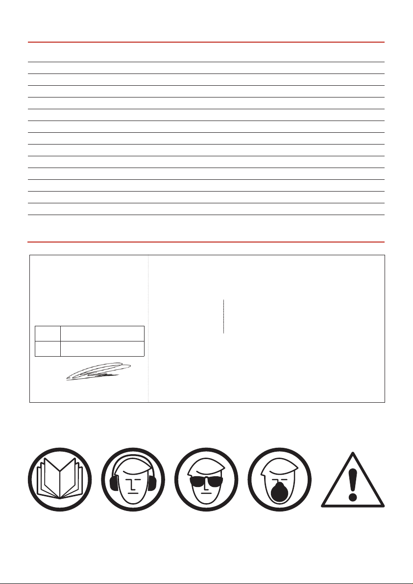
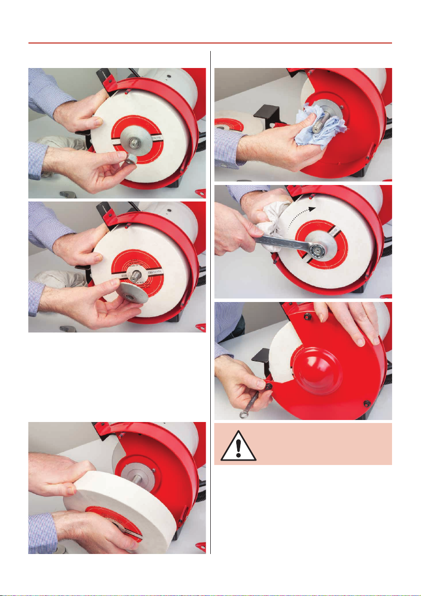
SPECIFIC SAFETY PRECAUTIONS FOR GRINDING MACHINES
1. Do not operate your machine until it is completely
assembled and installed according to the instructions.
2. If you are not familiar with the operation of grinding
machines obtain advice from your supervisor or instructor
or another qualified person.
3. Only use grinding wheels or attachments rated higher
than 3600 rpm with a 5/8”(16mm) arbor on this machine.
4. Never use a chipped or cracked wheel. Always inspect
each wheel before mounting it on the grinder. If during
inspection you discover a damaged grinding wheel, replace
it immediately.
5. Do not over tighten wheel nuts.
6. Always maintain a distance of 2mm or less between the
wheel and the tool rest. Adjust the tool rests as the wheels
decrease in size.
7. Ensure the tool rests are tightened so they cannot move
while in use.
8. Never grind on a cold wheel.The grinder should always
be run for at least one minute before applying work to it.
9. Never grind on the side of the wheel. Always grind on
the face of the wheel only.
10. Never apply coolant directly to a grinding wheel, it may
cause the bonding to fail. If the work piece becomes hot,
dip it into a water pot to cool it down.