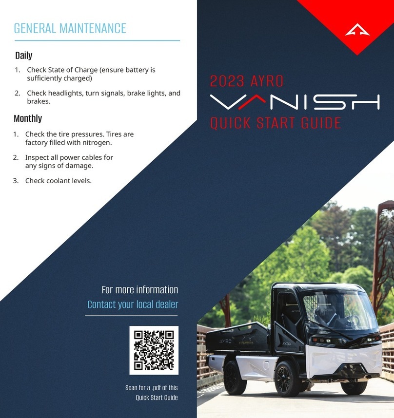
AYRO VANISH User manual

INTRO
Page 1of 48
Low
-
Speed Electric Vehicle
SERVICE MANUAL

CONTENTS
Page 2of 48
Table of Contents
1INTRODUCTION................................................................................................................................ 5
1.1 Applicability................................................................................................................................. 5
1.2 AYRO Service Department ........................................................................................................ 5
1.3 For Reference Only..................................................................................................................... 6
1.4 Compliance (NHTSA).................................................................................................................. 6
1.5 Applicability................................................................................................................................. 6
2GENERAL SAFETY.............................................................................................................................. 6
3CABIN .................................................................................................................................................. 7
3.1 Fascia and Trim............................................................................................................................ 7
3.1.1 Middle Front Fascia ............................................................................................................ 7
3.1.2 Upper Fascia ........................................................................................................................ 7
3.1.3 Lower Fascia ........................................................................................................................ 8
3.1.5 Interior Trim ......................................................................................................................... 9
3.1.6 Center Stack ........................................................................................................................ 9
3.1.7 Mirrors................................................................................................................................ 10
3.1.8 Wiper Arm ......................................................................................................................... 11
3.1.9 Wiper Motor assembly..................................................................................................... 11
3.1.10 Wiper Motor/Wiper Mechanism .................................................................................... 12
3.2 Upper Column Cover................................................................................................................ 12
3.2.1 Ignion switch................................................................................................................... 12
3.2.2 Lower dash panel .............................................................................................................. 12
3.3 Body ........................................................................................................................................... 13
3.3.1 Long Side Skirt................................................................................................................... 13
3.3.2 Short Side Skirt.................................................................................................................. 13
3.3.3 Rear Bumper...................................................................................................................... 13
4STEERING SYSTEM.......................................................................................................................... 15
4.1 Electric Power Steering (EPS).................................................................................................. 15
4.2 Rack and Pinion assembly........................................................................................................ 15
4.3 Steering wheel........................................................................................................................... 16
4.4 Steering Gearbox (90 degree).................................................................................................. 16
4.5 Tie Rods ..................................................................................................................................... 17

CONTENTS
Page 3of 48
4.6 Alignment................................................................................................................................... 17
5SUSPENSION.................................................................................................................................... 18
5.1 Front ........................................................................................................................................... 18
5.1.1 Upper Control Arm ........................................................................................................... 18
5.1.2 Lower Control Arm ........................................................................................................... 18
5.1.3 Coil-Over Shock ................................................................................................................ 19
5.1.4 Wheel Hub......................................................................................................................... 19
5.2 Rear............................................................................................................................................. 20
5.2.1 Leaf Springs ....................................................................................................................... 20
5.3 Motor Specificaons ................................................................................................................ 21
6JACK POINTS.................................................................................................................................... 22
7WHEELS/TIRES ................................................................................................................................ 23
7.1 Wheel Removal ......................................................................................................................... 23
1.2 Tire rotaon............................................................................................................................... 23
8BRAKES.............................................................................................................................................. 24
8.1 Verifying Brake Fluid Levels..................................................................................................... 24
8.2 Bleeding ..................................................................................................................................... 24
8.3 Brakes & Rotors ........................................................................................................................ 26
8.3.1 Brake Pads ......................................................................................................................... 26
8.3.2 Rotors ................................................................................................................................. 26
8.3.3 Calipers .............................................................................................................................. 27
8.3.4 Tools, Equipment, Materials:............................................................................................ 27
8.3.5 Removal.............................................................................................................................. 27
9CLIMATE CONTROL SYSTEM ........................................................................................................ 29
9.1 A/C System................................................................................................................................ 29
9.1.1 Compressor ....................................................................................................................... 29
9.1.2 Refrigerant and Fluids ...................................................................................................... 29
9.1.3 Condenser.......................................................................................................................... 29
9.1.4 Manifold and Hoses.......................................................................................................... 30
9.1.5 High/Low pressure switches ........................................................................................... 30
9.2 Heater System........................................................................................................................... 30
9.2.1 Blower Unit........................................................................................................................ 30

CONTENTS
Page 4of 48
9.2.2 Heang Element ............................................................................................................... 30
9.3 Common Issues with AC system............................................................................................. 30
10 COOLING SYSTEM ...................................................................................................................... 32
10.1 Radiator...................................................................................................................................... 32
10.1.1 Removal.............................................................................................................................. 33
10.1.2 Installaon ......................................................................................................................... 33
10.1.3 Removal.............................................................................................................................. 34
10.1.4 Installaon ......................................................................................................................... 34
11 Baery Charging & Maintenance................................................................................................ 35
11.1Baery Handling Precauons.................................................................................................. 35
11.2 CHARGING WARNING ........................................................................................................... 35
12 PAYLOAD CONFIGURATIONS................................................................................................... 38
13 DIAGRAMS/LAYOUTS (FUSES, WIRING)................................................................................. 39
13.1 Fuse Box..................................................................................................................................... 39
13.2 Wiring......................................................................................................................................... 40
14 SPARE PARTS LIST ............................................................................................................................ 41
14.1 Baeries and Charging System ............................................................................................... 41
14.2 Body ........................................................................................................................................... 42
14.3 Brakes, Disc ............................................................................................................................... 42
14.4 Coolant System ......................................................................................................................... 44
14.5 Suspension, Front & Rear......................................................................................................... 44
14.7 Wheel End Components.......................................................................................................... 46
14.8 Windshield................................................................................................................................. 46
14.9 Windshield Wiper & Washer system...................................................................................... 46

INTRODUCTION
Page 5of 48
1INTRODUCTION
AYRO designs and produces all-electric vehicles and e-delivery systems that redefine the very
nature of sustainability. We define sustainability as a ubiquitous construct. From re tread, fuel
cells, sound, and even discordant visuals, we apply engineering and arstry to every element of
our product mix.
Your vehicle(s) reflect our company’s commitment to advancing sustainable light electric
soluons, the passion of our leadership to deliver clean energy transportaon, and a beer
environment. These purpose-built and innovave EVs support a plurality of last-mile delivery,
micro distribuon, and campus / facility mobility needs.
The purpose of this Service Manual is to present informaon you require as an authorized
AYRO service representave. This Manual provides the instrucons and guidance needed for
the maintenance or repair of the AYRO Vanish Low Speed Electric Vehicle models (LSV and
Non-LSV).
Once you have read this Service Manual, you will:
•Be able to perform roune maintenance on the vehicle.
•Be able to find the informaon needed to service and support the vehicle.
•If so qualified, be able to perform service and maintenance on the vehicle’s electrical and
baery systems.
1.1 Applicability
This service manual applies to the following Model Years: 2023-2024
Baery Module Configuraon A applies to the following vehicle idenficaon numbers:
4A9AA11U1RR050006
4A9AA11U2RR050001
4A9AA11U3RR050007
4A9AA11U4RR050002
4A9AA11U5RR050008
4A9AA11U6RR050003
4A9AA11U8RR050004
4A9AA11UXRR050005
Baery Module Configuraon B applies to the following vehicle serial numbers and higher:
4A9AA11U7RR050009
1.2 AYRO Service Department
AYRO Service Department
Te l : +1 512.994.4917 Press 1 for Service Department (USA and Internaonal)
Email: su[email protected]
Web: www.AYRO.com

INTRODUCTION
Page 6of 48
1.3 For Reference Only
All informaon contained in this publicaon is based on the latest product informaon available
at the me of publicaon. Product improvements or changes may result in differences between
this Manual and the vehicle. Descripons, depicons, and/or procedures in this document are
intended for reference only.
No liability can be accepted for omissions or inaccuracies. AYRO, Inc. reserves the right to make
changes at any me, without noce and without incurring any obligaon to make the same or
similar changes to vehicles previously manufactured. Any reprinng or reuse of these
descripons, depicons, and/or procedures, whether in whole or in part, is expressly prohibited.
1.4 Compliance (NHTSA)
This vehicle complies with the U.S. Department of Transportaon Naonal Highway Traffic Safety
Administraon (NHTSA) low-speed vehicle regulaons and can be operated on many streets
posted with lower speed limits. Please familiarize yourself with all laws and regulaons
concerning the operaon of the vehicle in your area.
1.5 Applicability
This Manual applies to the following AYRO low-speed electric vehicles:
•AYRO Vanish LSV •AYRO Vanish Non-LSV
2GENERAL SAFETY
•Read your Owner’s Manual before operang this vehicle.
•Do not operate this vehicle under the influence of alcohol, drugs, or medicaon.
•This vehicle is not intended to be driven at speeds exceeding 25 MPH (40 km/h).
•Never exceed the passenger and cargo limits of this vehicle.
•Avoid sharp turns on inclines and at high speeds (may cause rollover).
•Reduce speed on wet and slippery surfaces and in turns.
•Set the park brake before performing maintenance, service, or leaving the vehicle.
•Remove key when leaving vehicle unaended.
•Stop vehicle before reversing direcon.
•Be aware of small children and objects behind you before reversing direcon.
•ALWAYS DRIVE SAFELY. FAILURE TO FOLLOW THESE WARNINGS COULD RESULT IN
SERIOUS OR FATAL INJURY.
WARNING: The voltage in the battery pack is enough to cause death by
electrocution. Never attempt to perform service on the
electric drive system, including the battery pack, unless you
are properly trained to work on electrical systems.

CABIN
Page 7of 48
3CABIN
3.1 Fascia and Trim
Tools, Equipment, Materials:
•Metric Allen hex wrench
•Metric wrench (typically 10 mm)
3.1.1 Middle Front Fascia
Tools, Equipment, Materials:
•Metric Allen hex wrench (typically 2.5 mm)
•Metric wrench (typically 10 mm)
Removal
1. Remove the two (2) screws from the driver side trim panel using a metric Allen wrench
and remove the panel. Repeat the step on the passenger side.
2. Remove the three (3) bolts that secure the driver side of the fascia to the cab frame using
a wrench. The middle fascia side bracket will come off as well. Repeat the step on the
passenger side.
3. Pop out the white front fascia.
Installaon
1. Align the middle front fascia with the proper slots for the tabs on the top and boom and
pop the fascia into posion.
2. Using the middle fascia side bracket and three (3) bolts, secure the middle fascia to the
cab frame with a wrench. Repeat the step on the passenger side.
3. Install the driver side trim panel by aligning the tabs on the trim piece with the proper
slots and secure with two (2) screws using a metric Allen wrench.
3.1.2 Upper Fascia
Tools, Equipment, Materials:
•Metric wrench (typically 10 mm)
Removal
1. Remove the middle front fascia (Ref. 3.1.1)
2. Remove the wiper arm (Ref. 3.1.8)
3. Remove the three (3) bolts that secure the upper fascia to the firewall bracket using a
wrench.

CABIN
Page 8of 48
4. Pop out the upper fascia and remove the windshield sprayer hose from the fing on the
inside of the fascia panel.
Installaon
1. Aach the windshield sprayer hose to the fing on the inside of the panel then insert the
upper fascia into posion by pung the top lip of the fascia under the windshield.
2. Secure the upper fascia to the firewall bracket with three (3) bolts using a wrench.
3.1.3 Lower Fascia
Tools, Equipment, Materials:
•Metric wrench (typically 10 mm)
Removal
1. Remove the middle front fascia (Ref. 3.1.1)
2. Remove the five (5) bolts that secure the lower fascia to the fire wall using a wrench.
3. Remove the lower fascia panel.
Installaon
1. Hold the lower fascia in place and secure it to the firewall using five (5) bolts and a
wrench.
Figure 1: Firewall locaon of Lower Fascia

CABIN
Page 9of 48
3.1.5 Interior Trim
Removal
1. Remove middle front fascia (Ref. 3.1.1).
2. Remove steering wheel (Ref. 4.3)
3. Remove upper column cover (Ref 3.2)
4. Remove Ignion switch. (Ref. 3.2.1)
5. Remove the four (4) nuts that secure the trim panel to the dash using a wrench; the outer
two (2) nuts have a trim retaining bracket that will need to be removed as well. Secure the
trim retaining brackets while removing the nuts so they do not get lost in the dash.
6. Remove the trim panel and trim insert.
***Process is the same for driver and passenger side interior trim panels***
3.1.6 Center Stack
Tools, Equipment, Materials:
•Metric Allen hex wrench (typically 2.5 mm)
•Metric wrench (typically 10 mm)
Removal
1. Remove the lower dash panel (Ref. 3.2.2).
2. Remove the pop-in cover behind the center stack.
3. Remove the two (2) boom center stack bracket bolts using a metric Allen hex wrench.
(Boom bolts are in the middle of the center stack, behind it, threaded in up towards the
roof of the cab)
4. Remove the top center stack bolts that secure the center stack to the upper dash frame
using a wrench. (The top bolts are visible once the pop-in cover is removed from the back
of the Center stack)
5. Remove the Center stack.
Installaon
1. Hold the center stack in posion and use two (2) bolts to mount the center stack to the
upper dash frame using a wrench.
2. Using a metric Allen wrench install the two (2) boom center stack bolts.
3. Install the pop-in cover behind the center stack.

CABIN
Page 10 of 48
3.1.7 Mirrors
Figure 2: Mirrors with 2 Bolts
Tools, Equipment, Materials:
•Metric Allen hex wrench (typically 6 mm)
Removal
1. Remove magnec cover from the mirror hinge.

CABIN
Page 11 of 48
2. Remove 2 mounng bolts securing the mirror hinge to the cab frame using a 6 mm Allen
wrench. Hold onto or secure the mirror so it does not fall or sustain damage when
removing the last bolt.
Installaon
1. Install the 2 mounng bolts that secure the mirror hinge to the cab frame using a 6 mm
Allen wrench.
2. Slide magnec cover into place.
3.1.8 Wiper Arm
Tools, Equipment, Materials:
•Marker o r Ta p e
•Metric wrench (typically 14 mm)
Removal
1. Mark the wiper arm angle.
2. Remove the wiper sprayer hose from the fascia fing.
3. Remove the wiper arm nut using a metric wrench.
4. Remove the wiper arm.
3.1.9 Wiper Motor assembly
Figure 3: Wiper Motor Assembly
•Tools, Equipment, Materials:

CABIN
Page 12 of 48
•Metric Allen hex wrench (typically 5 mm)
•Metric wrench (typically 10 mm)
Removal
1. Remove upper fascia (Ref. 3.1.2)
2. Disconnect the wiper motor connectors from the cab harness.
3. Remove the two (2) bolts that secure the wiper motor assembly to the firewall bracket
using an Allen wrench for the bolts and a metric wrench on the nut. (Ground wire secured
to driver side bolt)
3.1.10 Wiper Motor/Wiper Mechanism
Removal
1. Remove wiper motor assembly (Ref. 3.2.2)
2. Remove the 3 bolts that secure the wiper motor to the wiper mechanism using a wrench.
3.2 Upper Column Cover
Tools, Equipment, Materials:
•2.5 mm Allen hex wrench
•3 mm Allen hex wrench
Removal
1. Remove the steering wheel. (Ref. 4.3)
2. Remove grommets for instrument levers from the cover.
3. Remove 4 screws from the top half of the cover using 2.5 mm Allen wrench.
4. Remove the top cover.
5. Remove 3 bolts from the boom cover using a 3 mm Allen wrench.
6. Remove the boom cover.
3.2.1 Ignion switch
Removal
1. Squeeze the retaining tabs on both sides of the switch and push it out of the bracket.
2. Pull the switch out far enough to remove the connector from the back of the switch.
3.2.2 Lower dash panel
Tools, Equipment, Materials:
•Metric Allen hex wrench (typically 4 mm)

CABIN
Page 13 of 48
Removal
1. Remove mirrors. (Ref. 3.1.7)
2. Remove four (4) screws from the lower dash using a metric Allen wrench.
3. Remove the lower dash.
3.3 Body
3.3.1 Long Side Skirt
Tools, Equipment, Materials:
•Extracon tool for plasc trim rivet clips
•Metric wrench (typically 10 mm)
Removal
1. Remove six (6) plasc push-in tree clips that secure the side skirt to the wheel wells using
the proper removal tool. There are three (3) tree clips on each wheel well.
2. Remove the bolts that secure the side skirt to the front and middle skirt brackets using a
wrench. Each skirt bracket has two (2) bolts.
3. Remove the side skirt.
3.3.2 Short Side Skirt
Tools, Equipment, Materials:
•Extracon tool for plasc trim rivet clips
•Metric wrench (typically 10 mm)
Removal
1. Remove the three (3) plasc push-in tree clips that secure the side skirt to the rear wheel
well and two (2) tree clips that secure it to the rear bumper using the proper removal tool.
2. Remove the two (2) bolts that secure the skirt to the rear skirt bracket using a wrench.
3. Remove the side skirt.
3.3.3 Rear Bumper
Tools, Equipment, Materials:
•Extracon tool for plasc trim rivet clips
•Metric Allen hex wrench (typically 10 mm)
Removal
1. Remove the four (4) plasc push-in tree clips that secure the side skirts to the rear
bumper (2 on each side) using the proper removal tool.

CABIN
Page 14 of 48
2. Disconnect the 6-pin Deutsch connector that joins the chassis harness to the bumper
harness.
3. Disconnect the back-up camera cable connecon.
4. Remove the two (2) bolts that secure the bumper bracket to the chassis on the driver side
using a metric Allen hex wrench; repeat the step on the passenger side.
5. Remove the bumper.

STEERING SYSTEM
Page 15 of 48
4STEERING SYSTEM
4.1 Electric Power Steering (EPS)
Tools, Equipment, Materials:
•Metric wrench (typically 14 mm)
Removal
1. Disconnect the two connectors that are inserted into the EPS motor.
2. Loosen the two u-joints that are aached to the input and output shas of the EPS
motor.
3. Remove the four mounng bolts that secure the EPS motor using a wrench.
4. Remove the EPS motor.
Installaon
1. Install the EPS motor and secure with the four mounng bolts using a wrench. Tighten
unl seated.
2. Aach both the u-joints to the input and output shas of the EPS motor.
3. Connect the two connectors that plug into the EPS motor.
4.2 Rack and Pinion assembly
Tools, Equipment, Materials:
•Jack stands
•Imperial wrench (typically ½-in)
•Metric wrenches (typically 13 and 17 mm)
Removal
1. Place the vehicle on jackstands so that the front suspension and res off the ground.
2. Remove both front res. (Ref. in 7.1)
3. Remove e rod nut using a wrench. Remove e rod from wheel hub.
4. Remove the u-joint from the rack and pinion using a wrench.
5. Remove the four bolts that secure the rack and pinion to the mounng bracket using a
wrench on the bolt head and nut.
6. Remove the rack and pinion.
7. If the e rod ends are sll serviceable, remove them from the old rack and pinion and
install them on the new rack and pinion.
Installaon
1. Install the rack and pinion to the mounng bracket with the four bolts and nyloc nuts
using a wrench on the bolt head and on the nut. Tighten unl seated.

STEERING SYSTEM
Page 16 of 48
2. Insert the e rod into the wheel hub and secure it with the e rod nut using a wrench.
Tighten unl seated.
3. Aach the u-joint to the rack and pinion and ghten the u-joint bolt with a wrench.
4. Install the re. (Ref. 8.1)
5. Perform wheel alignment. (Ref. 4.6)
4.3 Steering wheel
Tools, Equipment, Materials:
•Metric Allen hex wrench (typically 5 mm)
•Metric socket (typically 24 mm)
•Steering Wheel Puller, if necessary
Removal
1. Remove three (3) bolts that aach the center steering wheel plate to the steering wheel
using a metric Allen.
2. Remove the steering wheel nut using a metric socket.
3. Remove the steering wheel. (Steering wheel puller may be necessary)
4.4 Steering Gearbox (90 degree)
Tools, Equipment, Materials:
•13 mm wrenches (typically 13 and 15 mm)
Removal
1. Remove lower fascia (Ref. 3.1.3)
2. Remove the bolt that secures the u-joint to the gearbox output sha using a metric
wrench. Do the same with the u-joint on the input sha.
3. Remove the four (4) bolts that secure the steering gearbox mounng bracket to the
chassis using a wrench.
4. Remove the steering gearbox mounng bracket bolts from the steering gearbox using a
wrench on the bolt and on the nut.
Installaon
1. Aach the steering gear box bracket to the new steering gear box.
2. Install the gearbox with four (4) bolts using wrenches. Tighten unl seated. Be sure to
insert the input sha of the gearbox into the carrier bearing that is mounted to the
firewall.
3. Connect the u-joints for the input and output sha of the steering gearbox using a
wrench.

STEERING SYSTEM
Page 17 of 48
4.5 Tie Rods
Tools, Equipment, Materials:
•Metric wrench (typically 17 mm)
•Marker or tape
Removal
1. Li the vehicle and place it on jackstands.
2. Remove the re. (Ref. 8.1)
3. Loosen the jam nut on the e rod.
4. Count the threads on the e rod or mark the threads with a marker to indicate how far to
thread the new e rod end on.
5. Remove the e rod nut that secures the e rod end to the wheel hub using a wrench.
6. Remove the e rod end from the e rod by unthreading it from the e rod.
Installaon
1. Install the new e rod end onto the e rod by threading it on to the mark on the treads or
to the thread count you took. (Do not ghten the jam nut)
2. Secure the e rod to the wheel hub with the e rod end nut using a wrench.
3. Install the re. (Ref. 7.1)
4. Perform wheel alignment. (Ref. 4.5.1)
5. Tighten the jam nut on the e rod.
4.6 Alignment
Tools, Equipment, Materials:
•Metric wrench (typically 14 mm)
1. Prepare the vehicle for an alignment using shop system setup.
2. Loosen the jam nut on both e rods when ready to make the adjustments.
3. Turn the e rod using a wrench to adjust the toe to get the correct alignment.
4. Tighten the jam nuts.

JACK POINTS
Page 18 of 48
5SUSPENSION
5.1 Front
5.1.1 Upper Control Arm
Tools, Equipment, Materials:
•Metric wrenches (typically 13, 17, and 18 mm)
Removal
1. Remove Wheel (Ref. 8.1)
2. Remove the coil-over shock. (Reference 5.1.3)
3. Disconnect brake line retaining mount bolt using a wrench.
4. Remove coer pin from castle nut on upper ball joint.
5. Remove castle nut using a wrench and separate upper ball joint from wheel hub.
6. Remove upper control arm mounng bolts using wrenches on the bolt and nut.
7. Remove the upper control arm.
Installaon
1. Install the upper control arm mounng bolts.
2. Insert the upper ball joint into the wheel hub and secure it with the castle nut using a
wrench. (Tighten the castle nut unl it is ght then back it off unl you can pass a coer
pin through the castle nut and ball joint).
3. Insert a new coer pin into the castle nut.
4. Secure the retaining bracket for the brake line onto the upper ball joint using a wrench.
5. Install the coil-over shock. (Ref. 5.1.3)
5.1.2 Lower Control Arm
Tools, Equipment, Materials:
•Metric wrenches (typically 16, 17, 18, and 21 mm)
Removal
1. Remove Wheel (8.1)
2. Remove the brake caliper and bracket. (Ref. 9.2.3)
3. Remove the e rod end from the wheel hub using a wrench on the e rod end nut.
4. Remove the lower shock mount bolt using wrenches on the bolt and nut.
5. Remove the lower ball joint nut using a wrench and separate the lower ball joint from the
wheel hub.
6. Remove the two lower control arm bolts using a wrench on the nut and bolt.
7. Remove the lower control arm.

SUSPENSION
Page 19 of 48
Installaon
1. Install the lower control arm using the two mounng bolts, thread on the lock nuts finger
ght. Do not ghten.
2. Aach the lower ball joint to the wheel hub and secure with the lower ball joint nut. Use
wrench and ghten unl seated.
3. Aach the lower shock mount with the shock mount bolt using a wrench on the bolt and
awrench on the nut. Tighten unl seated.
4. Tighten the lower control arm mount bolts unl seated.
5. Aach the e rod end to the wheel hub and secure with a wrench. Tighten unl seated.
6. Aach the brake caliper and bracket. (Ref. 8.2.3)
7. Install the wheel. (Ref. 7.1)
5.1.3 Coil-Over Shock
Tools, Equipment, Materials:
•Metric wrenches (typically 16 mm and 18 mm)
Removal
1. Remove Wheel (Ref. 8.1)
2. Remove lower shock mount bolt using wrenches on the bolt and nut.
3. Remove upper shock mount using wrenches on the bolt and nut.
4. Remove shock. (When removing the shock, secure from loss 2 each upper shock bushings
and sleeves.)
Installaon
1. Install the coil-over shock into the upper shock mount using the upper shock bolt. Tighten
the bolt and nut using a wrench on both. Ensure the shock bushings and sleeves are
correctly placed.
2. Secure the coil-over shock to the lower shock mount with the lower shock bolt using
wrenches on the bolt and nut.
5.1.4 Wheel Hub
Tools, Equipment, Materials:
•Metric wrench (typically 18 mm)
Removal
1. Remove Caliper and caliper bracket (Ref. 9.2.3).
2. Remove rotor (Ref. 9.2.2).
3. Remove the coer pin from the e rod castle nut then remove the castle nut with a
wrench and separate the e rod from the wheel (Ref. 4.5).

SUSPENSION
Page 20 of 48
4. Remove shock (Ref. 5.1.3)
5. Remove the coer pin from the upper ball joint and remove the castle nut with a wrench.
6. Separate the ball joint from the wheel hub.
7. Remove the lower ball joint nut using a wrench and separate the lower ball joint from the
wheel hub.
8. Remove the wheel hub.
5.2 Rear
5.2.1 Leaf Springs
Figure 4: Leaf Spring
Tools, Equipment, Materials:
•Metric wrenches (typically 13, 18, and 19 mm)
Removal
1. Gather all tools, materials, and proper PPE.
2. Ensure Vehicle is on a flat, level surface.
3. Verify work and parts to be serviced (Correct wheel, correct replacement parts etc.)
4. Li the vehicle and place jackstands on the frame; li high enough to remove the re.
5. Remove the re. (Ref. 8.1)
6. Place a jack underneath the axle and raise the axle to relieve tension on the leaf spring.
7. Use a wrench to remove the two U-bolts that secure the leaf spring to the axle.
8. Remove the two U-bolts and bump-stop bracket.
9. Remove the retaining nut that secures the leaf spring to the leaf spring retaining bolt.
10. Use a wrench to remove the front and rear leaf spring hanger bolts.
11. Remove the leaf spring.
Other manuals for VANISH
1
Table of contents
Other AYRO Utility Vehicle manuals