Midland SP-8 Quick start guide

1
www.roadwidener.com
Model SP-8 & 10
Midland Machinery Co., Inc.
101 Cranbrook Ext.
Tonawanda, NY 14150
Phone: 716-692-1200
Fax: 716-692-1206
www.midlandmachinery.com
SP-8 &10 Operation, Parts & Service Manual
Revision July 2012 Machine Serial Number : ______________


I
www.roadwidener.com
Model SP-8 & 10
Contents
1. IntroduCtIon And WArrAnty .................................................................... 2
1.1 Introduction...................................................................................................... 2
1.2 Serial Number .................................................................................................. 2
1.3 Warranty ........................................................................................................... 3
1.4 Engine Warranty .............................................................................................. 3
2. Component IdentIfICAtIon .......................................................................... 4
2.1 Overall Machine ............................................................................................... 4
2.2 Operators Console .......................................................................................... 5
3. speCIfICAtIons ........................................................................................... 6
3.1 SP-8/SPD-8 Specifications.............................................................................. 6
3.2 SP-10/SPD-10 Specifications.......................................................................... 6
4. sAfety ...................................................................................................... 7
4.1 Safety Alert Symbol And Signal Words ......................................................... 7
4.2 Hazards............................................................................................................. 7
4.2.1 mAIntenAnCe ..................................................................................................................... 7
4.2.2 Burn preventIon............................................................................................................... 7
4.2.3 pressurIzed HydrAulIC fluId And GreAse......................................................................... 8
4.2.4 HAzArdous CHemICAls ....................................................................................................... 8
4.2.5 fIre orexplosIon preventIon ......................................................................................... 8
4.3 Operation And Maintenance ........................................................................... 8
4.3.1 CAlIfornIA proposItIon 65 WArnInG ................................................................................ 10
4.3.2 prepAre for emerGenCIes............................................................................................... 10
4.3.3 donot AlloW rIders ..................................................................................................... 11
4.3.4 AvoId poWer lInes ......................................................................................................... 11
4.4 Hazards From Modifying Equipment ............................................................11
4.5 Safety Warning Labels .................................................................................. 12
5. operAtIon ............................................................................................... 18
5.1 Operational Safety ......................................................................................... 18
5.2 Startup Procedure ......................................................................................... 18
5.3 Strike-Off Blade Setup................................................................................... 19
5.3.1 posItIon BlAde .............................................................................................. 19
5.3.2 CHAnGe BlAde lenGtH..................................................................................................... 22
5.4 Push Roller Setup.......................................................................................... 24
5.4.1 pIvot pIn loCAtIon .......................................................................................................... 24
5.4.2 pusH roller dIstAnCe setup .......................................................................................... 25
5.4.3 HydrAulIC pusH roller dIstAnCe setup.......................................................................... 26
5.5 Set Hopper Gates........................................................................................... 26

www.roadwidener.com
II
Model SP-8 &10
5.6 Operation........................................................................................................ 27
5.7 Side Changeover For Material Discharge And Blade ................................. 28
5.7.1 sIde CHAnGeover for mAterIAl dIsCHArGe...................................................................... 28
5.7.2 BlAde sIde CHAnGeover ................................................................................................... 29
5.7.3 HydrAulIC extensIon CHAnGeover .................................................................................... 31
5.8 Loading For Transport................................................................................... 34
6. servICe And mAIntenAnCe ...................................................................... 36
6.1 Service Intervals ............................................................................................ 36
6.2 Drive Axle And Transmission Lubrication................................................... 38
6.3 Conveyor Belt ................................................................................................ 39
6.3.1 Adjust Conveyor Belt tensIon....................................................................................... 39
6.3.2 replACe Conveyor Belt.................................................................................................. 40
6.3.3 Conveyor Belt mAIntenAnCe ........................................................................................... 45
6.4 Hydraulic System Flushing Procedure........................................................ 46
6.4.1 flusH Conveyor system ................................................................................................. 47
6.4.2 flusH trACtIon drIve system ......................................................................................... 51
6.4.3 flusH Conveyor And trACtIon drIve system .................................................................. 52
7. revIsIon reCords ................................................................................... 53
7.1 Revision Record By Serial Number ............................................................. 53
8. fInAl AssemBly ....................................................................................... 54
8.1 Final Assembly (Dual Sided)......................................................................... 54
8.1.1 spd-8-001 rev-d (spd-8, duAl sIded) ........................................................................ 55
8.1.2 spd-10-001 rev-f (spd-10, duAl sIded) .................................................................... 55
8.2 Final Assembly (Single Sided)...................................................................... 56
8.2.1 sp-8-001 rev-H (sp-8, sInGle sIded).......................................................................... 57
8.2.2 sp-10-001 rev-f (sp-10, sInGle sIded) ........................................................................ 57
9. CHAssIs AssemBly ................................................................................... 58
9.1 Chassis Assembly (SP-8 & SPD-8), SP-005 Rev-F...................................... 59
9.2 Chassis Assembly (SP-10 & SPD-10), SP-395 Rev-F.................................. 61
9.3 Manual Shift Assembly SP-534 Rev-A ......................................................... 62
9.4 Trailer Axle And Brake Assembly SP-144 Rev-C ........................................ 64
9.4.1 InstruCtIons for BrAke yoke InstAllAtIon And Adjustment: .......................................... 65
10. Conveyor And Hopper AssemBly ......................................................... 66
10.1 Conveyor And Hopper Assembly, Dual Sided, SPD-808 .......................... 66
10.2 Conveyor And Hopper Assembly, Single Sided, SP-808.......................... 68
10.3 Adjustable Discharge Gate Assembly, SP-276 Rev-A .............................. 70
10.4 Deflector Assembly, SP-717 Rev-A ............................................................ 71
10.5 Bib Assembly, SP-718 ................................................................................. 72

III
www.roadwidener.com
Model SP-8 & 10
10.6 Push Roller Assembly SP-151 Rev-A......................................................... 73
11. BlAde And Column AssemBly ............................................................... 74
11.1 Blade And Column Assembly SP-8/SPD-8.................................................. 74
11.1.1 BlAde And Column AssemBly, rIGHt sIde, sp-579 rev-A ............................................. 74
11.1.2 BlAde And Column AssemBly, left sIde, sp-593 rev-A............................................... 76
11.2 Blade And Column Assembly SP-10/SPD-10............................................. 78
11.2.1 BlAde And Column AssemBly, rIGHt sIde, sp-420 rev-B ............................................. 78
11.2.2 BlAde And Column AssemBly, left sIde, sp-588 rev-A............................................... 80
11.3 Hydraulic Blade Extension Installation For SP-8, SP-751........................ 82
11.4 Hydraulic Blade Extension Installation For SP-10, SP-752...................... 83
11.5 Hydraulic Blade Extension Assembly, SP-470 Rev-A............................... 84
11.6 Adjustable Edger Plate Assembly , SP-744 Rev-A.................................... 85
12. enGIne And Controls AssemBly............................................................ 86
12.1 Engine And Controls Assembly SP-8/SPD-8............................................. 86
12.2 Engine And Controls Assembly SP-10/SPD-10......................................... 88
13. eleCtrICAl InstAllAtIon ........................................................................ 90
13.1 Electrical Install’n, Standard Config’n, Single Sided, SP-772 Rev-A ...... 90
13.2 Electrical Installation, Optional Neutral Position Brake Switch Safety .. 93
13.3 Electrical Installation, Optional Dual Discharge System ........................ 94
13.4 Electrical Installation, Other Options ........................................................ 96
13.5 Electrical Installation, Optional Auto Grade And Slope (Single Sided) . 98
13.6 Electrical Installation, Optional Auto Grade And Slope (Dual Sided) .. 100
13.7 Electrical Installation, Diode Box Assembly (Single Sided) SP-2161 ... 102
13.8 Electrical Installation, Diode Box Assembly (Dual Sided) SP-2162 ...... 104
14. optIonAl lIGHt pACkAGe .................................................................... 106
14.1 Optional Light Package Schematic SP-2065 Rev-A................................ 106
14.2 Optional Strobe Light Only Schematic SP-2065 Rev-A.......................... 109
15. operAtor Console AssemBly ............................................................. 110
15.1 Operator Console Assembly (Single Sided) SP-1355 Rev-B ..................111
15.2 Operator Console Assembly (Dual Sided) SPD-1355 Rev-B...................111
16. HydrAulIC InstAllAtIon ....................................................................... 112
16.1 Hydraulic Installation SPD-8, SPD-10 (Dual Sided), SP-770 Rev-C .......112
16.2 Hydraulic Installation SP-8, SP-10 (Single Sided), SP-769 Rev-C ..........118
17. nAmeplAte And deCAl loCAtIons ........................................................ 124

www.roadwidener.com
IV
Model SP-8 &10
18. optIons .............................................................................................. 130
18.1 Hydraulic Push Roller Assembly, SP-711 ................................................ 130
18.1.1 HydrAulIC InstAllAtIon, sp-707 rev-A ....................................................................... 131
18.1.2 HydrAulIC CylInder InstAllAtIon, sp-708 rev-A ........................................................ 131
18.1.3 eleCtrICAl InstAllAtIon, sp-866 rev-B...................................................................... 132
18.2 Diesel Washdown System, SP-273........................................................... 134
18.3 Trench Box Assembly ............................................................................... 136
18.3.1 trenCH Box AssemBly sA/sp duAl sIded, sA-1513 rev-A ........................................ 136
18.3.2 trenCH Box AssemBly sA/sp sInGle sIded, sA-726 rev-B........................................ 137
19. oem Component pArts And servICe InformAtIon ............................... 139

1
www.roadwidener.com
Model SP-8 & 10
sp-8 &10 operAtIon, pArts & servICe mAnuAl

www.roadwidener.com
2
Model SP-8 &10
1. IntroduCtIon And WArrAnty
1.1 IntroduCtIon
Congratulations on your purchase of the Midland
Machinery SP machine. This SP machine has
been designed and manufactured to the strictest
specications. It is our utmost desire that you achieve
success and are rewarded years of service from your
equipment purchase.
Carefully examine your machine upon receipt. Report
any damage immediately to the freight carrier and
register any claim. Should any material or manufacturing
defects be discovered, report your ndings to our
service department along with the model, serial number
and date of purchase. We want to know that you are
satised with the machine. As always, we welcome
input on how our products can be improved to serve
you better.
Read and understand this manual before using your
machine and follow all of the safety instructions. Keep
this manual with your machine at all times.
Some components may have separate operation and
maintenance manuals. Where this manual indicates
that you should read another manual, and you do
not have that manual, contact Midland Machinery for
assistance.
This manual explains the operation and routine
maintenance of the SP machine. It does not instruct
you how to transport, travel and/or operate on specic
roadways or terrain.
Information furnished in this manual does not include
all of the details of design, production, or variations
of the equipment. It does not cover all the possible
contingencies, which may arise during operation,
setup, or maintenance. Should special problems
arise, or further information be desired, please contact
Midland Machinery. This manual is provided to the SP
owner to assist in the safe operation and maintenance
of the equipment.
The text contained in this manual is for current
production models. Some instructions and maintenance
procedures may not apply to your specic unit.
Equipment modications from original design and
specications are strictly prohibited. Modications may
compromise safe operation of the machine, subjecting
users to serious injury or death and may void any
remaining warranty.
Midland Machinery reserves the right to change,
improve, modify or expand features of this equipment
at any time. Specications, models, or equipment are
subject to change without notice, and without incurring
any obligations to change, improve or expand features
of previously delivered equipment. Because of
variations in optional equipment and continued design
improvement, certain information contained within this
manual may not apply.
This Operator’s Manual does not replace, nor does its
use release the operator from observing all safety or
operating limitations as well as any applicable federal,
state, provincial or local regulations.
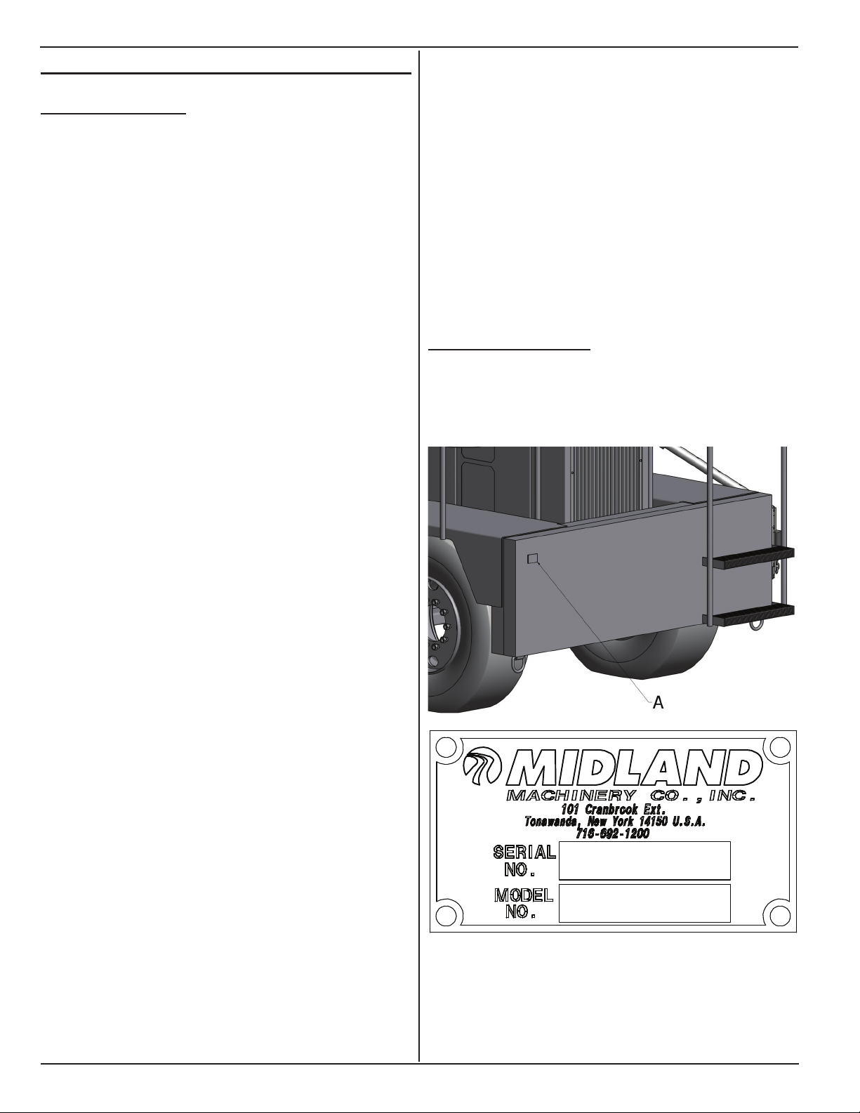
1.2 serIAl numBer
The serial number plate (A) is located on left rear
corner of the machine.

3
www.roadwidener.com
Model SP-8 & 10
1.3 WArrAnty
Midland warrants to the original purchaser only,
that each part of the Road Building Machine, or
components, or the other manufactured items, sold
herein, under normal use and service, shall be free
from defects in workmanship and material for 180 days
or 500 working hours, from initial start-up, whichever
occurs rst, except that this warranty shall not apply
to tires, engines, batteries, manufactured hydraulic
components, which items shall be subject only to the
original manufacturer’s warranty. No adjustment shall
be made for defective items unless notice is given in
writing within ten days after the defect is noted and the
equipment is immediately taken out of service. Use of
equipment thereafter shall constitute acceptance and
waiver of the alleged defects.
This warranty shall be fullled by Midland repairing or
replacing at its factory, products or parts that have been
returned to it with transportation charges prepaid and
that appear to its satisfaction to have been defective in
workmanship or material.
THE FOREGOING SPECIFIC WARRANTY IS IN
LIEU OF ANY OTHER EXPRESSED OR IMPLIED
WARRANTIES INCLUDING ANY IMPLIED WARRANTY
OF MERCHANTABILITY OR FITNESS FOR A
PARTICULAR USE, AND ANY OTHER OBLIGATION
ON PART OF MIDLAND. MIDLAND SHALL NOT BE
RESPONSIBLE UNDER THIS WARRANTY FOR
ANY LOSS OF USE OF THE VEHICLE, LOSS OF
TIME, INCONVENIENCE, COMMERCIAL LOSS OR
CONSEQUENTIAL DAMAGE.
NO AGENT, EMPLOYEE OR REPRESENTATIVE OF
MIDLAND HAS ANY AUTHORITY TO BIND MIDLAND
TO ANY AFFIRMATION, REPRESENTATION OR
WARRANTY CONCERNING THE MACHINE SOLD
UNDER THIS CONTRACT NOT STATED WITHIN, AND
UNLESS AN AFFIRMATION, REPRESENTATION OR
WARRANTY MADE BY AN AGENT, EMPLOYEE OR
REPRESENTATIVE IS SPECIFICALLY INCLUDED
WITHIN THIS WRITTEN AGREEMENT, IT SHALL
NOT BE ENFORCEABLE AGAINST MIDLAND.
1.4 enGIne WArrAnty
To receive full warranty protection, All John Deere
engines must be registered with John Deere company.
To register your engine with John Deere, please
visit the website: https://jdpswarrantyreg.deere.com/
WarrantyReg/viewRegistration.do.
Warranty Period is normally 2000 engine hours or 2
years from the date of purchase which ever occurs rst.
ALL WARRANTY REPAIR REQUESTS MUST BE
RECEIVED THROUGH AND PROCESSED BY
SUPERIOR DIESEL INC.
TO AUTHORIZE LOCAL JOHN DEERE DEALER
REPAIRS, CONTACT SUPERIOR DIESEL INC AT
PHONE NUMBER 1-888-803-9175/SERVICE OR
THROUGH E-MAIL AT SER[email protected].
UNAUTHORIZED REPAIR MAY VOID ANY ENGINE
WARRANTY.

www.roadwidener.com
4
Model SP-8 &10
2. Component IdentIfICAtIon
2.1 overAll mACHIne
A - Engine
B - Engine controls
C - Hydraulic Pumps
D - Manual Pack
E - Operator Console
F - Blade And Column Assembly (L/S)*
G - Conveyor And Hopper Assembly
H - Discharge Gate Assembly**
J - Conveyor Belt
K - Conveyor Motor
L - Push Roller Assembly
M - Guide Rod Assembly
N - Deector Assembly
P - Bib Assembly
Q - Blade And Column Assembly (R/S)
R - Outer Edger Assembly
S - Hydraulic Blade Extension**
T - Blade Restraint Assembly
U - Hydraulic Tank
* Available only in dual side configuration
** Available as option

5
www.roadwidener.com
Model SP-8 & 10
2.2 operAtors Console
A - Steering Wheel
B - Engine Kill Switch
C - Parking Brake Applied Indicator
D - Dual Alarm
E - Parking Brake (E-Stop) Button
F - Engine Throttle Switch
G - Conveyor On/Off Switch
H - Conveyor Speed Controller
J - Travel Controller
K - Horn Button
L - Conveyor Direction Switch*
M - Blade Hydraulic Extension Switch**
N - Blade Slope Switch
P - Blade Grade Switch
Q - Hydraulic Push Roller Switch**
* Available only in dual side configuration
** Available as option

www.roadwidener.com
6
Model SP-8 &10
3. speCIfICAtIons
3.1 sp-8/spd-8 speCIfICAtIons
Dimensions-
Length: 19 ft.
Width: Travel - 11 ft. 2 in.
Track (Front) - 80 in.
Track (Rear) - 60 in.
Turn Radius : 15 ft.
Height: 7 ft. 10 in.
Weight: 19,000 lbs.
Wheelbase: 98 in.
Tires: Front : 2 x 425/65R/22.5 Pneumatic
Rear : 2 x 11 R22.5 Pneumatic
Engine/Drive -
John Deere Diesel Model 4045D Tier III 80 hp
Front Wheel Drive, Front Wheel Steering.
Two Speed Hydrostatic Transmission.
Hydraulic Service Brakes
SAHR Emergency/ Parking Brake.
Travel Speed: 0 - 11 mph.
Working Speed: 0 - 150 ft/min.
Strike-Off Blade -
4 - 8 ft. Maximum Spread Width.
18 in. Tall, 1 ft. & 2 ft. long, Modular Blade Sections.
Optional 2 - 4 ft. Hydraulic Extension Section.
Adjustable Height Outer Edger.
Hydraulic Grade Control - 12 in. Above / Below.
Hydraulic Slope Control +/- 16%.
Receiving Hopper -
11 ft. 2 in. Width, Adjustable Discharge Gates.
3 cubic yard Capacity
Conveyor -
Right or Left Hand Discharge.
Heat And Oil Resistant Conveyor Belt
Chain Driven 18 in. Conveyor Belt with
Variable Speed Hydraulic Drive to 450 TPH Output.
Push Rollers -
Extendable, Oscillating, Self Cleaning
Specications subject to change without notice.
3.2 sp-10/spd-10 speCIfICAtIons
Dimensions-
Length: 19 ft. 4 IN.
Width: Travel - 11 ft. 2 in.
Track (Front) - 80 in.
Track (Rear) - 60 in.
Turn Radius : 15 ft.
Height: 8 ft. 3 in.
Weight: 27,500 lbs.
Wheelbase: 98 in.
Tires: 4 x 425/65R/22.5 Pneumatic
Engine/Drive -
John Deere Diesel Model 4045T Tier III 100 hp Turbo
Charged
Front Wheel Drive, Front Wheel Steering.
Two Speed Hydrostatic Transmission.
Hydraulic Service Brakes
SAHR Emergency/Parking Brake.
Travel Speed: 0 - 11 mph.
Working Speed: 0 - 150 ft/min.
Strike-Off Blade -
1-10 ft. Maximum Spread Width.
18 in. Tall, 1 ft. & 2 ft. long, Modular Blade Sections.
Optional 2 - 4 ft. Hydraulic Extension Section.
Adjustable Height Outer Edger.
Hydraulic Grade Control - 12 in. Above / Below.
Hydraulic Slope Control +/- 16%.
Receiving Hopper -
11 ft. 2 in. Width, Adjustable Discharge Gates.
3 cubic yard Capacity
Conveyor -
Right or Left Hand Discharge.
Heat And Oil Resistant Conveyor Belt
Chain Driven 18 in. Conveyor Belt with
Variable Speed Hydraulic Drive to 450+ TPH Output.
Push Rollers -
Extendable, Oscillating, Self Cleaning
Specications subject to change without notice.

7
www.roadwidener.com
Model SP-8 & 10
4. sAfety
4.1 sAfety Alert symBol And sIGnAl
Words
This manual covers the SP-8, SPD-8, SP-10 and
SPD-10 machines produced by Midland Machinery
(henceforth mentioned as “SP” or “SP machine”, unless
required otherwise). Before setting up, operating or
servicing SP machine, you must read, understand
and follow the instructions and safety warnings in this
manual. Your machine may not be equipped with some
of the optional equipment shown in the illustrations in
this manual.
All personnel that will be operating, maintaining
and working around the SP machine must read and
understand these documents before interacting with
the SP.
NEVER ALLOW ANYONE TO OPERATE THIS
EQUIPMENT WITHOUT PROPER TRAINING!
If you have any safety concerns or questions that are
not covered by this manual, please contact Midland
Machinery at 1-716-692-1200.
^
This symbol means ATTENTION! BECOME ALERT!
YOUR SAFETY IS INVOLVED!
The level of risk is indicated by the following signal
words:
^ DANGER
DANGER - Indicates a hazardous situation,
which, if not avoided, WILL result in death
or serious injury.
^ WARNING
WARNING - Indicates a hazardous
situation, which, if not avoided, could
result in death or serious injury.
^ CAUTION
CAUTION - Indicates a hazardous situation,
which, if not avoided, could result in minor
or moderate injury.
NOTICE
NOTICE - Indicates a situation that could
result in damage to the equipment or other
property.
4.2 HAzArds
SP machine is a complex machines and its operation
requires a high level of machine knowledge and skill.
Safe use is dependant on correct operation and proper
maintenance.
4.2.1 mAIntenAnCe
Before servicing machine:
1. Park on a rm level surface.
2. Apply parking brakes.
3. Turn engine off, close and lock control panel
cover.
4. Chock tires.
5. Place a “Do Not Operate” tag on operators
console.
Read and understand this manual. If you do not
understand any part of this manual, contact your
dealer.
Always wear face or eye protection, safety shoes, and
other protective items as required.
Do not make unauthorized modications to machine.
Contact your dealer before you weld, cut/drill holes, or
make any other modications to your machine. Always
use Midland Machinery replacement parts.
If you must service machine with engine running, have
someone in constant visual contact who can shut off
engine if necessary.
If you must service machine with an attachment raised,
block attachment up to prevent attachment falling in
case of pressure or power loss.
4.2.2 Burn preventIon
Battery acid causes severe burns. Batteries contain
sulfuric acid. Avoid contact with skin, eyes or clothing.

www.roadwidener.com
8
Model SP-8 &10
• If acid contacts skin: Flush with water. Apply baking
soda or lime to neutralize acid and get immediate
medical attention.
• If acid contacts eyes: Flush with water for 15
minutes and get immediate medical attention.
• If acid is swallowed: Drink large quantities of water
or milk, then drink milk of magnesia, beaten eggs, or
vegetable oil and get immediate medical attention.
Keep battery fully charged to avoid battery freezing. If
battery electrolyte freezes, battery can explode if you
try to charge or jump start the battery.
Explosive release of coolant can cause serious burns.
Turn off engine and let engine cool before removing
coolant cap. Loosen cap to rst stop to relieve pressure
before removing cap completely.
4.2.3 pressurIzed HydrAulIC fluId And GreAse
Hydraulic uid and grease injected into your skin
may cause serious injury or death. Keep your hands
and body away from any pressurized leak. Tighten
connections before applying pressure. Never use your
hand to check for leaks; use a piece of cardboard
or paper. If uid is injected into the skin, it must be
surgically removed within a few hours or gangrene
may result. Get immediate medical attention.
4.2.4 HAzArdous CHemICAls
Fluids, lubricants, coolants, can be hazardous. Before
servicing machine, check Material Safety Data Sheet
(MSDS) for each uid or lubricant to understand
the product, safe handling procedures, and rst aid
measures relating to the product. Follow this information
when servicing machine.
Do not drain or pour any uids or lubricants on
ground. Check with local environmental agencies,
recycling centers, or your dealer for correct disposal
information.
4.2.5 fIre orexplosIon preventIon
Engine fuel can cause an explosion or re. Do not
service or refuel with engine running or near open
ame. Do not weld or smoke near fuel. Never allow
fuel to spill on hot machine components.
Keep sparks and ames away from batteries to prevent
explosion of hydrogen gas in and near a battery. Other
precautions include:
• When disconnecting battery cables, disconnect
negative (-) cable rst.
• When connecting battery cables, connect negative
(-) cable last.
• Do not short circuit battery posts with metal items.
Remove all trash and debris from engine. Do not store
oily rags or ammable materials on or near engine.
Always have a re extinguisher available on machine.
Keep the extinguisher serviced according to
manufacturer’s instructions.
Check for fuel, oil and hydraulic uid leaks. Replace
worn or damaged hoses or lines. Clean up spilled
uids.
4.3 operAtIon And mAIntenAnCe
^ WARNING
Prevent serious injury or death.
Read and understand this manual before
operating machine.
Always stop engine and remove key before
leaving operators console.
Never allow anyone near machine during
operation.
Travel at a safe speed.
^ WARNING
Crush hazard.
Chock wheels before mechanically
releasing brakes.
Do not operate machine with brakes
mechanically released.
^ WARNING
Carbon monoxide hazard.
Do not operate engine with machine in an
enclosed building or conned area.
Avoid actions or areas that expose you and
others to carbon monoxide.

9
www.roadwidener.com
Model SP-8 & 10
^ WARNING
Prevent serious injury or death from
moving parts.
Moving parts can crush and dismember.
Do not operate without guards and shields
in place.
Disconnect and lockout power source
before adjusting or servicing.
^DANGER
Sulfuric acid can cause blindness or
severe burns. When servicing battery:
• Wear appropriate protective equipment.
• No smoking, sparks or ames near
battery.
If sulfuric acid gets on your skin or in your
eyes:
• Immediately ush the affected area with
clean water for 15 minutes.
• Seek immediate medical attention.
^ WARNING
Prevent serious injury or death.
Before performing inspections, service or
maintenance:
• Park machine on rm, level surface and
engage parking brake.
• Switch engine off.
• Close and lock control panel cover.
• Chock tires.
^ WARNING
Corrosive chemicals may be present.
Exposure may result in serious injury.
Wear appropriate protective equipment.
Read and follow handling instructions and
MSDS for the chemical.
^ WARNING
Prevent serious injury or death.
Do not operate, work on or around
machine while under the inuence of
alcohol, drugs or if feeling ill.
^ WARNING
Flammable material. Diesel fuel.
No open ames and no smoking while
fueling.
^ WARNING
Entanglement hazard.
Loose tting clothing and long hair can
become entangled in moving or rotating
parts.
Do not wear loose tting clothing.
Long hair must be tied back or netted.
Keep clear of moving components.
Never operate machine with open or
removed guards or shields.
Observe federal, state/provincial and local safety codes
and regulations that apply to the job site.
^ WARNING
Prevent serious injury or death.
Walk platforms and covers may be
slippery. Keep steps, handrails, and
platform clean.
Use handrails and face machine when
climbing up or down steps. Use three
points of support when climbing up or
down steps.
Use caution while walking on machine to
avoid falling. Do not jump off machine.

www.roadwidener.com
10
Model SP-8 &10
^ WARNING
Noise hazard.
Prolonged exposure to loud noise can
cause impairment or loss of hearing
Operator, workers and bystanders must
use ear protection while machine is in
operation.
^ WARNING
Prevent serious injury or death.
Do not operate with covers, guards or
doors open or removed.
Keep clear of moving components.
Follow lockout procedure before servicing.
^ WARNING
Prevent serious injury or death.
Do not mount or dismount moving
equipment.
Do not enter hopper while machine is
running.
^ WARNING
Prevent serious injury or death.
Hot and high pressure hydraulic oil.
Allow to cool before servicing.
^ WARNING
Pinch point.
Push rollers may move suddenly.
Keep clear during operation.
^ WARNING
Pressurized uids can penetrate the skin.
Hydraulic hoses can fail from age, damage
and exposure.
Do not search for hydraulic leaks without
body and face protection. A tiny, almost
invisible leak can penetrate the skin,
thereby requiring immediate medical
attention.
Use wood or cardboard to detect hydraulic
leaks, never use your hands.
^ WARNING
Prevent serious injury or death.
Operator must wear seat belt while
operating machine.
NOTICE
Dispose of waste properly.
Improper disposal of waste can harm the
environment.
Use leak proof container when draining
uids. Do not use food or beverage
containers.
Contact local environmental or recycling
center for proper way to recycle or dispose
of waste.
4.3.1 CAlIfornIA proposItIon 65 WArnInG
Diesel engine exhaust and some of its constituents are
known to the State of California to cause cancer, birth
defects and other reproductive harm.
Battery posts, terminals and related accessories contain
lead and leads compounds, chemicals known to the
State of California to cause cancer, birth defects and
other reproductive harm. Wash hands after handling.
4.3.2 prepAre for emerGenCIes
Be prepared in case of emergencies.

11
www.roadwidener.com
Model SP-8 & 10
Keep a re extinguisher and rst aid kit close to
machine.
Keep emergency phone numbers in a easy to access
location.
Know your location so emergency services can locate
you if an emergency arises.
4.3.3 donot AlloW rIders
Never allow riders on machine. Machine is equipped to
carry the operator only.
4.3.4 AvoId poWer lInes
^WARNING
Prevent electrocution.
Death or serious injury can result if
equipment comes near or contacts power
lines.
Electrocution can occur without direct
contact.
DO NOT leave operator’s seat if any part of equipment
contacts electric lines or cables.
4.4 HAzArds from modIfyInG equIpment
Do not modify or alter machine. Modifying or altering
may cause machine to be unsafe and will void the
manufacturers’ warranty.

www.roadwidener.com
12
Model SP-8 &10
4.5 sAfety WArnInG lABels

13
www.roadwidener.com
Model SP-8 & 10

www.roadwidener.com
14
Model SP-8 &10
This manual suits for next models
3
Table of contents
Other Midland Utility Vehicle manuals
Popular Utility Vehicle manuals by other brands

Charles Machine Works
Charles Machine Works Ditch Witch HF482 Operator's manual

TrailMax
TrailMax TD-24-T(5+20) manual

Agri-Fab
Agri-Fab 45-03033 owner's manual

Primo Water
Primo Water UT5x10-26HSS Assembly instructions

TrailMaster
TrailMaster MID XRS Setup instructions

Club Car
Club Car Precedent 4-Passenger owner's manual