Arctic Cat WILDCAT/X User manual

[ROV]
SERVICE MANUAL
2014
WILDCAT/X - WILDCAT 4/4X

FOREWORD
This Arctic Cat Service Manual contains service, maintenance, and troubleshooting information for certain 2014 Arctic
Cat Wildcat models (see cover). The complete manual is designed to aid service personnel in service-oriented applica-
tions.
This manual is divided into sections. Each section covers a specific vehicle component or system and, in addition to the
standard service procedures, includes disassembling, inspecting, and assembling instructions. When using this manual
as a guide, the technician should use discretion as to how much disassembly is needed to correct any given condition.
The service technician should become familiar with the operation and construction of each component or system by
carefully studying this manual. This manual will assist the service technician in becoming more aware of and efficient
with servicing procedures. Such efficiency not only helps build consumer confidence but also saves time and labor.
All Arctic Cat publications and decals display the words Warning, Caution, Note, and At This Point to emphasize
important information. The symbol ! WARNING identifies personal safety-related information. Be sure to fol-
low the directive because it deals with the possibility of serious personal injury or even death. A CAUTION identi-
fies unsafe practices which may result in vehicle-related damage. Follow the directive because it deals with the
possibility of damaging part or parts of the vehicle. The symbol NOTE: identifies supplementary information wor-
thy of particular attention. The symbol AT THIS POINT directs the technician to certain and specific proce-
dures to promote efficiency and to improve clarity.
At the time of publication, all information, photographs, and illustrations were technically correct. Some photographs
used in this manual are used for clarity purposes only and are not designed to depict actual conditions. Because Arctic
Cat Inc. constantly refines and improves its products, no retroactive obligation is incurred.
All materials and specifications are subject to change without notice.
Keep this manual accessible in the shop area for reference.
Product Service and
Warranty Department
Arctic Cat Inc.
© 2013 Arctic Cat Inc. December 2013
®™ Trademarks of Arctic Cat Inc., Thief River Falls, MN 56701

1
TABLE OF CONTENTS
General Information ....................................................................... 2
General Specifications .................................................................. 2
Torque Specifications.................................................................... 3
Torque Conversions (ft-lb/N-m)..................................................... 4
Drive Belt Break-In Procedure ...................................................... 4
Gasoline - Oil - Lubricant .............................................................. 4
Genuine Parts ............................................................................... 5
Preparation For Storage................................................................ 5
Preparation After Storage ............................................................. 5
Periodic Maintenance/Tune-Up ..................................................... 6
Periodic Maintenance Chart.......................................................... 6
Lubrication Points.......................................................................... 7
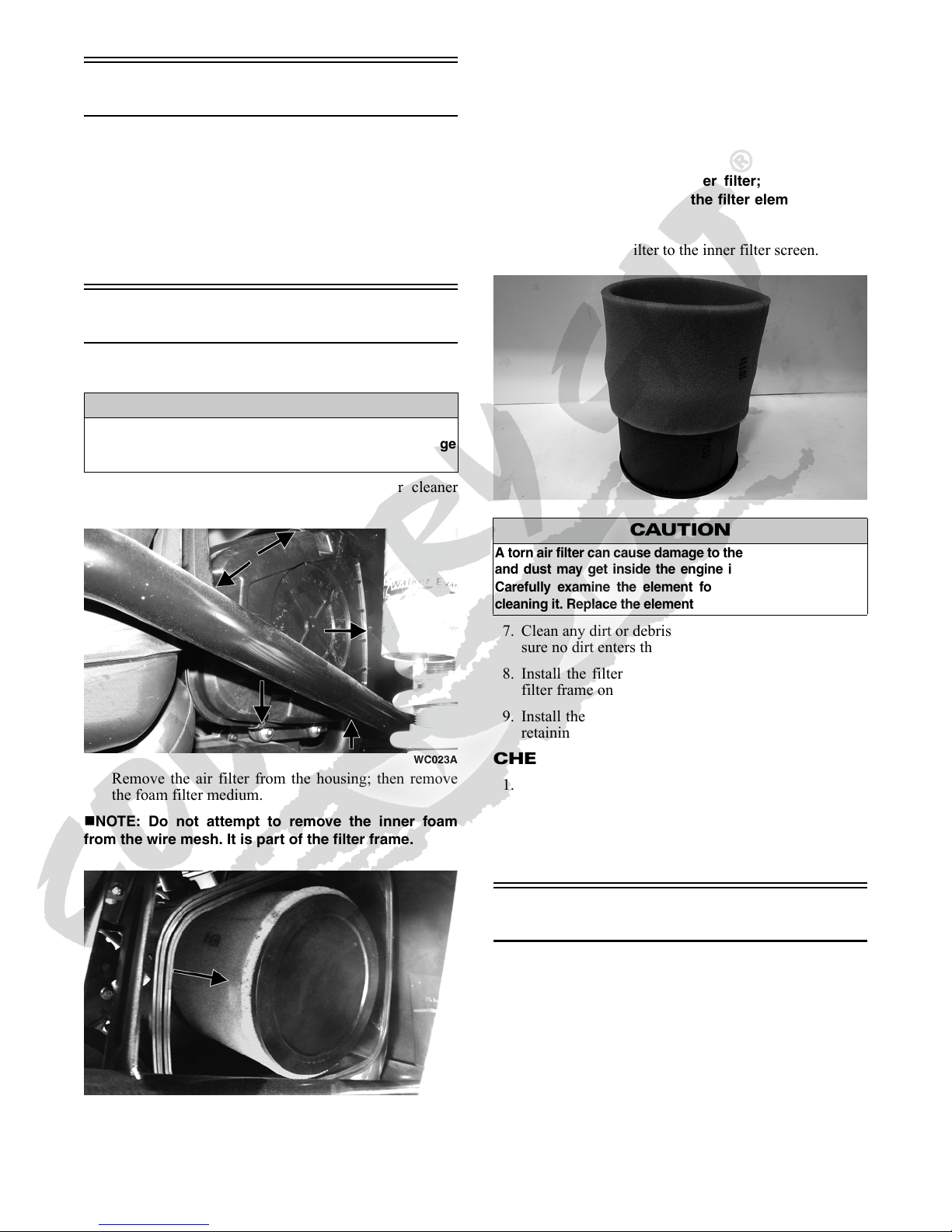
Air Filter......................................................................................... 7
Valve/Tappet Clearance ................................................................ 7
Testing Engine Compression ........................................................ 8
Spark Plugs................................................................................... 9
Muffler/Spark Arrester................................................................... 9
Engine/Transmission Oil - Filter .................................................. 10
Front Differential - Rear Drive Lubricant ..................................... 11
Driveshaft/Coupling..................................................................... 11
Nuts/Bolts/Cap Screws ............................................................... 11
Headlight/Taillight-Brakelight....................................................... 11
Shift Lever/Shift Cable ................................................................ 13
Hydraulic Brake System.............................................................. 13
Burnishing Brake Pads................................................................ 15
Replacing V-Belt ......................................................................... 16
Steering/Frame/Controls ............................................................. 18
Hood ........................................................................................... 18
Front Bumper Assembly (X/4X/Limited)...................................... 18
Rear Body Panel......................................................................... 18
Electronic Power Steering (EPS) ................................................ 19
Rack and Pinion Assembly ......................................................... 22
Steering Wheel ........................................................................... 23
Steering Shaft ............................................................................. 24
Steering Knuckles ....................................................................... 26
Checking/Adjusting Front Wheel Alignment................................ 27
Accelerator Pedal ........................................................................ 28
Shift Lever ................................................................................... 28
Shift Cable .................................................................................. 29
LCD Gauge/Indicator Lights/Dash Switches............................... 29
Exhaust System .......................................................................... 30
Cargo Box ................................................................................... 30
Seats........................................................................................... 30
Doors .......................................................................................... 31
Roof (X Limited) .......................................................................... 32
Troubleshooting........................................................................... 33
Engine/Transmission ................................................................... 34
Troubleshooting........................................................................... 35
Removing Engine/Transmission (Wildcat/X) ............................... 37
Removing Engine/Transmission (Wildcat 4/4X) .......................... 41
Top-Side Components ................................................................ 46
Left-Side Components ................................................................ 63
Removing Left-Side Components ............................................... 63
Servicing Left-Side Components ................................................ 66
Installing Left-Side Components ................................................. 68
Right-Side Components.............................................................. 70
Removing Right-Side Components............................................. 70
Servicing Right-Side Components.............................................. 71
Installing Right-Side Components............................................... 77
Center Crankcase Components.................................................. 79
Separating Crankcase Halves..................................................... 79
Disassembling Crankcase Half ................................................... 80
Servicing Center Crankcase Components.................................. 82
Assembling Crankcase Half ........................................................ 89
Joining Crankcase Halves........................................................... 90
Installing Engine/Transmission (Wildcat/X) ................................. 92
Installing Engine/Transmission (Wildcat 4/4X) ............................ 95
Fuel/Lubrication/Cooling .............................................................99
Throttle Body ...............................................................................99
Gas Tank ...................................................................................100
Gas/Vent Hoses.........................................................................101
Oil Filter/Oil Pump .....................................................................101
Oil Cooler ..................................................................................102
Liquid Cooling System...............................................................102
Radiator.....................................................................................102
Thermostat ................................................................................103
Fans...........................................................................................104
Water Pump...............................................................................104
Fuel Pump/Fuel Level Sensor ...................................................105
Troubleshooting .........................................................................107
Electrical System........................................................................108
Battery .......................................................................................108
RPM Limiter...............................................................................109
Accessory Receptacle/Connector .............................................109
Brakelight Switch .......................................................................109
Engine Coolant Temperature (ECT) Sensor..............................110
Fan Motor ..................................................................................110
Power Distribution Module (PDM) .............................................110
Ignition Coil................................................................................111
Manifold Absolute Pressure/Inlet Air Temperature (MAP/IAT)
Sensor....................................................................................111
Speed Sensor............................................................................112
Electronic Power Steering (EPS)...............................................112
Ignition Switch ...........................................................................114
Headlight Switch........................................................................114
Drive Select Switch ...................................................................114
Reverse Override Switch ...........................................................115
Front Drive Actuator ..................................................................115
Stator Coil/Crankshaft Position (CKP) Sensor ..........................115
Starter Motor .............................................................................116
Starter Relay .............................................................................117
Engine Control Module (ECM) ..................................................117
Regulator/Rectifier.....................................................................117
Headlights .................................................................................118
Taillight-Brakelight .....................................................................118
Ignition Timing ...........................................................................118
Tilt Sensor .................................................................................118
Throttle Position Sensor (TPS)..................................................119
EFI Diagnostic System ..............................................................120
Troubleshooting .........................................................................125
Drive and Brake Systems ..........................................................126
Front Drive Actuator ..................................................................126
Front Differential ........................................................................127
Driveshaft (Wildcat 4/4X)...........................................................139
Drive Axles ................................................................................142
Rear Gear Case ........................................................................145
Hub............................................................................................151
Hydraulic Brake Caliper (Wildcat)..............................................153
Hydraulic Brake Caliper (X/Wildcat 4/4X)..................................156
Master Cylinder Assembly.........................................................159
Troubleshooting Drive System...................................................161
Troubleshooting Brake System..................................................161
Suspension .................................................................................162
Shock Absorbers .......................................................................162
Shock Absorbers (Limited) .......................................................176
Front A-Arms .............................................................................178
Rear Trailing Arms.....................................................................181
Wheels and Tires ......................................................................183
Troubleshooting .........................................................................184

2
General Information
NOTE: Some photographs and illustrations used in
this manual are used for clarity purposes only and are
not designed to depict actual conditions.
NOTE: Whenever a part is worn excessively, cracked,
or damaged in any way, replacement is necessary.
NOTE: Never reuse a lock nut. Once a lock nut has
been removed, it must be replaced with a new lock nut.
General Specifications
* Visible at plug threads.
Specifications subject to change without notice.
CHASSIS
Curb Weight (approx) 649.5 kg (1432 lb) - Wildcat
658.6 kg (1452 lb) - X
681.3 kg (1502 lb) - X Limited
738.9 kg (1629 lb) - Wildcat 4
ROPS Tested Curb Weight 981 kg (2162 lb) - Wildcat/X
1265 kg (2789 lb) - Wildcat 4/4X
Length (overall) 304.8 cm (120 in.) - Wildcat
314.9 cm (124 in.) - X
378.5 cm (149 in.) -
Wildcat
4/
4X
Height (overall) 167.0 cm (65.8 in.)
Width (overall) 162.6 cm (64 in.)
Tire Size (Wildcat/Wildcat 4/4X) 26 x 9R14 (Front)
26 x 11R14 (Rear)
Tire Size (X) 27 x 9R14 (Front
27 x 11R14 (Rear)
Tire Inflation Pressure 0.84 kg/cm² (12 psi) - Wildcat/X
1.12 kg/cm² (16 psi) - Wildcat 4/
4X/Limited
MISCELLANY
Spark Plug Type NGK CPR8E
Spark Plug Gap 0.5-0.6 mm (0.019-0.024 in.)
Gas Tank Capacity 33.3 L (8.8 U.S. gal.)
Coolant Capacity 3.3 L (3.5 U.S. qt)
Front Differential Capacity 200 ml (6.7 fl oz)*
Rear Drive Capacity 175 ml (5.9 fl oz)*
Engine Oil Capacity 2.8 L (3.0 U.S. qt) - Overhaul
2.3 L (2.4 U.S. qt) - Change
Gasoline (recommended) 87 Octane Regular Unleaded -
Wildcat/Wildcat 4
91 Octane Regular Unleaded - X/
4X
Engine Oil (recommended) Arctic Cat ACX All Weather Syn-
thetic
Front Differential/Rear Drive Lubri-
cant
SAE Approved 80W-90
Hypoid
Belt Width 32 mm (1.25”)
Brake Fluid DOT 4
Taillight/Brakelight High Intensity LED
Headlight High Intensity LED
ELECTRICAL SYSTEM
Spark Plug Cap 5000 ohms
Ignition Coil Resistance (primary)
(secondary)
Less than 1 ohm
1.8M ohms
Ignition Coil Primary Voltage Battery Voltage
Stator Coil (crankshaft position sensor)
Resistance (AC generator)
150-250 ohms
Less than 1 ohm
Crankshaft Position Sensor AC Voltage 2.0 or more
AC Generator Output (no load) 75 AC volts @ 5000 RPM
Ignition Timing 10° BTDC @ 1500 RPM
VALVES AND GUIDES
Valve Face Diameter (intake)
(exhaust)
31.6 mm
27.9 mm
Valve/Tappet Clearance (intake)
(cold engine) (max) (exhaust)
0.1016 mm
0.1524 mm
Valve Guide/Stem Clearance (max) 0.013 mm
Valve Guide/Valve Stem Deflection (max)
(wobble method)
0.35 mm
Valve Guide Inside Diameter 5.000-5.012 mm
Valve Stem Outside Diameter 4.972-4.987 mm
Valve Stem Runout (max) 0.1 mm
Valve Head Thickness (min) 2.3 mm
Valve Face/Seat Width (intake)
(exhaust)
2.25 mm
2.60 mm
Valve Seat Angle 45° +15’/+30’
Valve Face Radial Runout (max) 0.2 mm
Valve Spring Free Length (min) 38.7 mm
Valve Spring Tension @ 31.5 mm 19.0 kg (42 lb)
CAMSHAFT AND CYLINDER HEAD
Cam Lobe Height (min) 34.18 mm
Camshaft Journal Oil Clearance (max) 0.07 mm
Camshaft Journal Holder(right & center)
Inside Diameter (left)
21.94-22.04 mm
17.44-17.48 mm
Camshaft Journal Outside(right & center)
Diameter (left)
21.96-21.98 mm
17.48-17.53 mm
Camshaft Runout (max) 0.05 mm
Rocker Arm Inside Diameter (max) 12.018 mm
Rocker Arm Shaft Outside Diameter
(min)
11.97 mm
Cylinder Head/Cover Distortion (max) 0.05 mm
CYLINDER, PISTON, AND RINGS
Piston Skirt/Cylinder Clearance 0.05 mm
Cylinder Bore 91.992-92.008 mm
Piston Diameter 15 mm from Skirt End 91.949-91.959 mm
Piston Ring Free End Gap (min)(1st/2nd) 12.5 mm
Bore x Stroke 92 x 71.6 mm
Cylinder Trueness (max) 0.075 mm
Piston Ring End Gap - Installed 0.38 mm
Piston Ring to Groove Clearance (1st)
(max) (2nd)
0.034 mm
0.033 mm
Piston Ring Groove Width (1st/2nd)
(oil)
1.202-1.204 mm
2.501-2.503 mm
Piston Ring Thickness (1st/2nd) 1.170-1.195 mm
Piston Pin Bore (max) 20.012 mm
Piston Pin Outside Diameter (min) 19.995 mm
CRANKSHAFT
Connecting Rod (small end inside diame-
ter) (max)
20.021 mm
Connecting Rod (big end side-to-side) 0.95 mm
Connecting Rod (small end deflection)
(max)
0.3 mm
Crankshaft (web-to-web) 98 mm
Crankshaft Runout (max) 0.03 mm
Oil Pump Gerotor Clearance (max) 0.15 mm

3
Torque Specifications
Torque (ft-lb) Tolerance
0-15 ±20%
16-39 ±15%
40+ ±10%
EXHAUST COMPONENTS
Part Part Bolted To Torque
ft-lb N-m
Exhaust Pipe Cylinder Head 20 27
Spark Arrester Muffler 68
BRAKE COMPONENTS
Brake Disc** Hub 15 20
Brake Hose Caliper 20 27
Brake Hose Master Cylinder 20 27
Master Cylinder Frame 25 34
Caliper Holder**** Knuckle 20 27
Front Brake Caliper (Wildcat 4/
4X)
Knuckle 35 48
SUSPENSION COMPONENTS (Front)
A-Arm Frame 40 54
Knuckle**** Ball Joint 35 48
Shock Absorber Frame/Lower A-Arm 40 54
SUSPENSION COMPONENTS (Rear)
Sway Bar Bracket Frame 40 54
Sway Bar Link Sway Bar Arm 35 48
Sway Bar Link Lower Trailing Arm 35 48
Trailing Arm Cross Mount (min) 60 81
Lower Trailing Arm Cross-
Mount
Frame 60 81
Shock Absorber (Lower) Trailing Arm 35 48
Shock Absorber (Upper) Frame 40 54
Knuckle Lower Trailing Arm 60 81
Knuckle Upper Trailing Arm 35 48
Upper/Lower Lateral Link Knuckle 40 54
Upper/Lower Lateral Link Frame 40 54
CHASSIS/ROPS ASSEMBLY
Shift Lever Shift Axle Bracket 20 27
Shift Cable Shift Arm 811
Front ROPS Tube Frame 35 48
Top ROPS Support Front/Rear ROPS Tubes 35 48
Rear ROPS Tube Lower ROPS Support 35 48
Cargo Box Cargo Box Support 68
Seat Belt Retractor Frame 60 81
Seat Belt Flange Frame 60 81
Seat Belt Buckle Frame 60 81
Shoulder Anchor ROPS Hoop 35 48
Front Bumper Frame 20 27
Upper Bumper Support Front Bumper 20 27
STEERING COMPONENTS
Steering Wheel** Steering Wheel Shaft 25 34
Rack and Pinion Bracket Frame 20 27
Rack and Pinion Assembly Frame 25 34
Tie Rod** Rack 55 75
Tie Rod End** Knuckle 55 74
Jam Nut Tie Rod End 10 14
Flex-Shaft Hold-Down Strap Housing 50
in.-lb
5.5
Tilt Steering Link Frame 10 14
EPS Mounting Bracket EPS 35 48
EPS Assembly Frame 20 27
Steering Shaft Upper Collar Tilt Assembly 20 27
Steering Shaft Lower U-Clamp Frame 79
DRIVE TRAIN COMPONENTS
Part Part Bolted To Torque
ft-lb N-m
Rear Drive/Gear Case Frame 38 52
Drive Coupler (Front) Drive Flange 40 54
Drive Coupler (Rear) Drive Flange 40 54
Front Differential Frame/Differential Bracket 38 52
Set Screw** (Wildcat 4/4X) Carrier Bearing 75
in.-lb
8.5
Center Front Driveshaft (Wildcat
4/4X)
Front Driveshaft 40 54
Center Rear Driveshaft (Wildcat
4/4X)
Rear Driveshaft 40 54
Carrier Bearing Bracket 35 52
Carrier Bearing Support Bracket Frame 20 27
Input Shaft Assembly Gear Case Housing 23 31
Secondary Drive Gear Nut Secondary Drive Gear 48
in.-lb
6
Pinion Housing Differential Housing 23 31
Thrust Button** Gear Case Cover 811
Differential Housing Cover*** Differential Housing 23 31
Lock Collar Differential Housing 125 170
Hub***** Axle (min) 250 340
Oil Drain Plug Front Differential - Rear Drive 45
in.-lb
5
Oil Fill/Level Plug Front Differential - Rear Drive 16 22
Wheel Hub (20 ft-lb increments) 80 108
Bead Lock (Limited) Wheel 11 15
ENGINE/TRANSMISSION
Oil Drain Plug Engine 20 27
Front Engine Through-Bolt Frame 40 54
Rear Engine Through-Bolt Frame 40 54
Clutch Shoe** Crankshaft 221 300
Clutch Cover/Housing Assembly Crankcase 811
Lower Crankcase Cover (6 mm) Crankcase 10 14
Lower Crankcase Cover (8 mm) Crankcase 21 28
Crankcase Half Crankcase Half 21 28
Cylinder Head (Cap Screw) Crankcase (step 1)
(step 2)
(final)
20
30
37
27
41
50
Cylinder Head Nut (6 mm) Cylinder 8.5 11.5
Cylinder Head Nut (8 mm) Cylinder 21 28
Valve Cover Cylinder Head 8.5 11.5
Driven Clutch Bolt** Input Shaft 60 81
Drive Clutch Bolt Crankshaft 60 81
Drive Clutch Spider***** Fixed Driven Hub 265 359
Magneto Cover Crankcase 8.5 11.5
Tappet Cover Valve Cover 8.5 11.5
Crankshaft Spacer Crankshaft 28 38
Oil Pump Drive Gear** Crank Balancer Shaft 62 84
Output Pinion Nut* Output Shaft 150 204
Outer Magneto Cover Magneto Cover 811
Rotor/Flywheel Nut** Crankshaft 107 145
Cam Sprocket** Camshaft 10 14
CVT Cover Crankcase 811
Secondary Drive Gear Nut* Secondary Drive Output
Shaft
200 270
Oil Filter Cover Crankcase 811
Shift Cam Stopper Crankcase 811
Shift Cam Stopper Spring Shift Cam Stopper 811
Shift Cam Plate Shift Cam Shaft 811
Shifter Housing Crankcase 811
Starter Motor Crankcase 811
V-Belt Cover Crankcase 811
Oil Pump Cover Crankcase 811
Oil Strainer Cap Crankcase 811
Intake Boot Clamp Intake Boot 30
in.-lb
3.4
Starter One-Way Clutch** Rotor/Flywheel 26 35
Fuel Rail Engine 68

4
*w/Red Loctite #263***w/Green Loctite #270
**w/Red Loctite #271 ****w/“Patch-Lock”
*****w/Primer #7649 and Loctite #277
Torque Conversions
(ft-lb/N-m)
Drive Belt Break-In
Procedure
New drive belts require a break-in period of approximately
25 miles. During this period, drive the vehicle for 25 miles
at 3/4 throttle or less while varying throttle position (but
not exceeding 40 mph). By varying throttle position, the
exposed cord on the side of a new belt will be conditioned
allowing the drive belt to gain its optimum flexibility and
will extend drive belt life.
Gasoline - Oil - Lubricant
RECOMMENDED GASOLINE
The recommended gasoline to use is 87 (Wildcat/Wildcat
4) or 91 (X/4X) minimum octane regular unleaded. In
many areas, oxygenates are added to the gasoline. Oxy-
genated gasolines containing up to 10% ethanol or 5%
methane are acceptable gasolines.
When using ethanol blended gasoline, it is not necessary to
add a gasoline antifreeze since ethanol will prevent the
accumulation of moisture in the fuel system.
RECOMMENDED ENGINE/
TRANSMISSION OIL
The recommended oil to use is Arctic Cat ACX All
Weather synthetic engine oil, which has been specifically
formulated for use in this Arctic Cat engine. Although
Arctic Cat ACX All Weather synthetic engine oil is the
only oil recommended for use in this engine, use of any
API certified SM 0W-40 oil is acceptable.
OILCHARTJ
RECOMMENDED FRONT
DIFFERENTIAL/REAR DRIVE
LUBRICANT
The recommended lubricant is Arctic Cat Gear Lube or an
equivalent gear lube which is SAE approved 80W-90 hypoid.
This lubricant meets all of the lubrication requirements of the
Arctic Cat vehicle front differential and rear drive.
ENGINE/TRANSMISSION (cont)
Air Filter Housing Engine 68
Ground Wire Engine 811
Stator Coil Magneto Cover (New) 15 20
Stator Coil Magneto Cover (Original) 13 18
ft-lb N-m ft-lb N-m ft-lb N-m ft-lb N-m
11.4 26 35.4 51 69.4 76 103.4
22.7 27 36.7 52 70.7 77 104.7
34.1 28 38.1 53 72.1 78 106.1
45.4 29 39.4 54 73.4 79 107.4
56.8 30 40.8 55 74.8 80 108.8
68.2 31 42.2 56 76.2 81 110.2
79.5 32 43.5 57 77.5 82 111.5
810.9 33 44.9 58 78.9 83 112.9
912.2 34 46.2 59 80.2 84 114.2
10 13.6 35 47.6 60 81.6 85 115.6
11 15 36 49 61 83 86 117
12 16.3 37 50.3 62 84.3 87 118.3
13 17.7 38 51.7 63 85.7 88 119.7
14 19 39 53 64 87 89 121
15 20.4 40 54.4 65 88.4 90 122.4
16 21.8 41 55.8 66 89.8 91 123.8
17 23.1 42 57.1 67 91.1 92 125.1
18 24.5 43 58.5 68 92.5 93 126.5
19 25.8 44 59.8 69 93.8 94 127.8
20 27.2 45 61.2 70 95.2 95 129.2
21 28.6 46 62.6 71 96.6 96 130.6
22 29.9 47 63.9 72 97.9 97 131.9
23 31.3 48 65.3 73 99.3 98 133.3
24 32.6 49 66.6 74 100.6 99 134.6
25 34 50 68 75 102 100 136
CAUTION
Do not use white gas. Only Arctic Cat approved gaso-
line additives should be used.
CAUTION
On the Wildcat/Wildcat 4, any oil used in place of the
recommended oil could cause serious engine damage.
Do not use oils which contain graphite or molybdenum
additives. These oils can adversely affect clutch opera-
tion. Also, not recommended are racing, vegetable, non-
detergent, and castor-based oils.
CAUTION
Any lubricant used in place of the recommended lubri-
cant could cause serious front differential/rear drive
damage.

5
FILLING GAS TANK
Since gasoline expands as its temperature rises, the gas
tank must be filled to its specified capacity only. Expan-
sion room must be maintained in the tank particularly if
the tank is filled with cold gasoline and then moved to a
warm area.
Tighten the gas tank cap securely after filling the tank.
Genuine Parts
When replacement of parts is necessary, use only genuine Arc-
tic Cat parts. They are precision-made to ensure high quality
and correct fit. Refer to the appropriate Illustrated Parts Man-
ual for the correct part number, quantity, and description.
Preparation For Storage
1. Clean the seat cushion (cover and base) with a damp
cloth and allow it to dry.
2. Clean the vehicle thoroughly by washing dirt, oil,
grass, and other foreign matter from the entire vehicle.
Allow it to dry thoroughly. DO NOT get water into
any part of the engine or air intake.
3. Either drain the gas tank or add Fuel Stabilizer to the
gas in the gas tank. Remove the air filter housing
cover and air filter. Start the engine and allow it to
idle. Using Arctic Cat Engine Storage Preserver, rap-
idly inject the preserver into the air filter opening for a
period of 10 to 20 seconds; then stop the engine.
Install the air filter and housing cover.
4. Plug the exhaust hole in the exhaust system with a
clean cloth.
5. Apply light oil to the plungers of the shock absorbers.
6. Tighten all nuts, bolts, cap screws, and screws. Make
sure rivets holding components together are tight.
Replace all loose rivets. Care must be taken that all
calibrated nuts, cap screws, and bolts are tightened to
specifications.
7. Fill the cooling system to the bottom of the stand pipe
in the radiator neck with properly mixed coolant.
8. Disconnect the battery cables; then remove the bat-
tery, clean the battery posts and cables, and store in a
clean, dry area.
9. Store the vehicle indoors in a level position.
Preparation After
Storage
Taking the vehicle out of storage and correctly preparing it
will assure many miles and hours of trouble-free riding.
1. Clean the vehicle thoroughly.
2. Clean the engine. Remove the cloth from the exhaust
system.
3. Check all control wires and cables for signs of wear or
fraying. Replace if necessary.
4. Change the engine/transmission oil and filter.
5. Check the coolant level and add properly mixed cool-
ant as necessary.
6. Charge the battery; then install. Connect the battery
cables.
7. Check the entire brake systems (fluid level, pads,
etc.), all controls, headlights, taillight, brakelight, and
headlight aim; adjust or replace as necessary.
8. Tighten all nuts, bolts, cap screws, and screws making
sure all calibrated nuts, cap screws, and bolts are tight-
ened to specifications.
9. Check tire pressure. Inflate to recommended pressure
as necessary.
10. Make sure the steering moves freely and does not
bind.
11. Check the spark plugs. Clean or replace as necessary.
! WARNING
Always fill the gas tank in a well-ventilated area. Never
add fuel to the gas tank near any open flames or with
the engine running. DO NOT SMOKE while filling the
gas tank.
! WARNING
Do not overflow gasoline when filling the gas tank. A
fire hazard could materialize. Always allow the engine to
cool before filling the gas tank.
! WARNING
Do not over-fill the gas tank.
CAUTION
Prior to storing the vehicle, it must be properly serviced
to prevent rusting and component deterioration.
CAUTION
If the interior of the air filter housing is dirty, clean the
area before starting the engine.
CAUTION
Avoid storing outside in direct sunlight and avoid using
a plastic cover as moisture will collect on the vehicle
causing rusting.
CAUTION
The ignition switch must be in the OFF position prior to
installing the battery or damage may occur to the igni-
tion system.
CAUTION
Connect the positive battery cable first; then the nega-
tive.

6
Periodic Maintenance/
Tune-Up
This section has been organized into sub-sections showing
common maintenance procedures.
SPECIAL TOOLS
A number of special tools must be available to the techni-
cian when performing service procedures in this section.
Refer to the current Special Tools Catalog for the appropri-
ate tool description.
NOTE: Special tools are available from the Arctic
Cat Service Department.
Periodic Maintenance
Chart
A = Adjust I = Inspect C = Clean L = Lubricate R = Replace T = Tighten
* Service/Inspect more frequently when operating in adverse conditions.
** When using an API certified SM 0W-40 oil.
*** When using Arctic Cat ACX All Weather synthetic oil, oil change and strainer inspection interval can be increased to every
1,000 miles or every year.
Description p/n
Compression Tester Kit 0444-213
Oil Filter Wrench 0644-389
Timing Light 0644-296
Valve Clearance Adjuster 0444-255
Item
Initial Service After
Break-In (First
Month or 100 Miles)
Daily Monthly
(100 Miles)
Every 3
Months (300
Miles)
Every 6
Months (500
Miles)
Annually
(1500 Miles)
As
Needed
Battery II C
Fuses IR
Air Filter II* R
Valve/Tappet Clearance IIA
Engine Compression I
Spark Plugs I I I R (4000 Mi
or 18 Mo)
Muffler/Spark Arrester CR
Gas Hoses II R(2Yrs)
Throttle Cable Ends/Accelerator Pedal Pivot II C-L A-R
Engine-Transmission Oil/Filter R R*/R**/R*** A/R
Front Differential - Rear Drive Lubricant II R
Tires/Air Pressure II R
Steering Components II I R
V-Belt IlR
Suspension (Ball joint boots, drive axle boots
front and rear, tie rods, differential and rear
drive bellows)
II R
Nuts/Bolts/Cap Screws TT A
Ignition Timing I
Headlight/Taillight-Brakelight II R
Switches II R
Shift Lever IA-L
Gauge/Indicators II R
Frame/Welds II l
Electrical Connections lC
Complete Brake System II
Brake Pads II* R
Brake Fluid II R(2Yrs)
Brake Hoses II R(4Yrs)
Coolant/Cooling System II R(2Yrs)
Wheel Lug Nuts TT

7
Lubrication Points
It is advisable to lubricate certain components periodically
to ensure free movement. Apply light oil to the compo-
nents using the following list as reference.
A. Accelerator Pedal Pivot/Cable Ends
B. Brake Pedal Pivot
C. Shift Cable
Air Filter
CLEANING AND INSPECTING FILTER
1. Unsnap the five fasteners securing the air cleaner
housing cover and remove the cover.
WC023A
2. Remove the air filter from the housing; then remove
the foam filter medium.
NOTE: Do not attempt to remove the inner foam
from the wire mesh. It is part of the filter frame.
WC024A
3. Fill a wash pan larger than the filter with a non-flam-
mable cleaning solvent; then dip the inner filter and
outer foam medium in the solvent and wash them.
NOTE: Foam Filter Cleaner and Foam Filter Oil are
available from Arctic Cat.
4. Dry both filter components.
5. Put the foam filter in a plastic bag; then pour in air fil-
ter oil and work the filter.
NOTE: Apply oil to the inner filter; then carefully
squeeze excessive oil from the filter element. Do not
twist foam to remove oil.
6. Attach the foam filter to the inner filter screen.
WC140
7. Clean any dirt or debris from inside the air cleaner. Be
sure no dirt enters the throttle body.
8. Install the filter in the air filter housing. Position the
filter frame on top.
9. Install the air filter housing cover and secure with the
retaining clips.
CHECKING AND CLEANING DRAINS
1. Inspect the drain beneath the main housing for debris
or liquid. Remove and clean the drain bulb if contami-
nated.
2. Wipe any accumulation of oil or gas from the filter
housing and drain.
Valve/Tappet Clearance
To check and adjust valve/tappet clearance, use the follow-
ing procedure.
NOTE: The engine must be cold for this procedure.
NOTE: On the Wildcat/X, the seats, left-side seat belt
and anchor, left-side heat shroud and shield, cargo
box, and rear body panel must be removed for this pro-
cedure.
NOTE: On the Wildcat 4/4X, the rear seats, left-rear
seat belt retractor, left-side heat shroud and shield,
cargo box, and rear body panel must be removed for
this procedure.
CAUTION
Failure to inspect the air filter frequently if the vehicle is
used in dusty, wet, or muddy conditions can damage
the engine.
CAUTION
A torn air filter can cause damage to the vehicle engine. Dirt
and dust may get inside the engine if the element is torn.
Carefully examine the element for tears before and after
cleaning it. Replace the element with a new one if it is torn.

8
1. Remove the spark plugs and timing inspection plug;
then remove the tappet covers (for more detailed
information, see Engine/Transmission - Servicing
Top-Side Components).
NOTE: Remove the crankshaft end cap and install the
special cap screw (left-hand threads) to rotate the engine.
2. Rotate the crankshaft to the TDC position on the com-
pression stroke of the front cylinder. The stamped “F”
must be visible.
GZ063
NOTE: At this point, the rocker arms and adjuster
screws must not have pressure on them.
Feeler Gauge Procedure
A. Using a feeler gauge, check each valve/tappet clear-
ance. If clearance is not within specifications, loosen
the jam nut and rotate the tappet adjuster screw until
the clearance is within specifications. Tighten each
jam nut securely after completing the adjustment.
CC007D
B. Rotate the engine 270° to the TDC position of the rear
cylinder; then repeat step A. The stamped “R” must be
visible.
GZ059
Valve Adjuster Procedure
A. Place the Valve Clearance Adjuster onto the jam
nut securing the tappet adjuster screw; then rotate
the valve adjuster dial clockwise until the end is
seated in the tappet adjuster screw.
B. While holding the valve adjuster dial in place, use
the valve adjuster handle and loosen the jam nut;
then rotate the tappet adjuster screw clockwise
until friction is felt.
C. Align the valve adjuster handle with one of the
marks on the valve adjuster dial.
D. While holding the valve adjuster handle in place,
rotate the valve adjuster dial counterclockwise
until proper valve/tappet clearance is attained.
NOTE: Refer to the appropriate specifications in
Feeler Gauge Procedure sub-section for the proper
valve/tappet clearance.
NOTE: Rotating the valve adjuster dial counter-
clockwise will open the valve/tappet clearance by
0.05 mm (0.002 in.) per mark.
E. While holding the adjuster dial at the proper clear-
ance setting, tighten the jam nut securely with the
valve adjuster handle.
F. Rotate engine 270° to the TDC position of the rear
cylinder; then repeat steps A-E for the rear cylinder.
3. Install the spark plugs and timing inspection plug; then
remove the cap screw from the crankshaft and install the
crankcase end cap.
NOTE: Apply grease to the end cap to aid in installa-
tion.
4. Place the two tappet covers into position making sure
the proper cap screws are with the proper cover.
Tighten the cap screws securely.
Testing Engine
Compression
NOTE: The engine should be warm (operating tem-
perature) and the battery fully charged for an accurate
compression test. In the event the engine cannot be
run, cold values are included.
CAUTION
The feeler gauge must be positioned at the same angle
as the valve and valve adjuster for an accurate measure-
ment of clearance. Failure to measure the valve clear-
ance accurately could cause valve component damage.
VALVE/TAPPET CLEARANCE
Intake 0.1016 mm (0.004 in.)
Exhaust 0.1524 mm (0.006 in.)

9
NOTE: On the Wildcat/X, the seats and rear body panel
must be removed and the radiator tilted rearward for this
procedure.
NOTE: On the Wildcat 4/4X, the rear seats and rear
body panel must be removed and the radiator tilted rear-
ward for this procedure.
1. Remove the high tension lead from the spark plugs.
2. Using compressed air, blow any debris from around
the spark plugs.
3. Remove the spark plugs; then attach the high tension
leads to the plugs and ground the plugs on the cylinder
heads well away from the spark plug holes.
4. Attach the Compression Tester Kit.
5. While holding the throttle in the full-open position,
crank the engine over with the electric starter until the
gauge stops climbing (five to 10 compression strokes).
Compression should be as shown in the chart.
NOTE: If the throttle is not held in the full-open posi-
tion, compression reading can be low.
6. If compression is abnormally low, verify the following:
A. Starter cranks engine over (normal speed).
B. Gauge is functioning properly.
C. Throttle in the full-open position.
D. Valve/tappet clearance correct.
E. Engine warmed up.
F. Intake not restricted.
NOTE: To service top-side components, see Engine/
Transmission.
7. Pour approximately 30 ml (1 fl oz) of oil into the spark
plug holes, reattach the gauge, and retest compression.
8. If compression increases to normal, service the piston
rings (see Engine/Transmission - Servicing Top-Side
Components).
Spark Plugs
A light brown insulator indicates the plug is correct. A white or
dark insulator indicates that the engine may need to be serviced.
To maintain a hot, strong spark, keep the plug free of carbon.
Adjust the gap to 0.5-0.6 mm (0.019-0.024 in.).
ATV-0051
ATV0052E
When installing a spark plug, be sure to tighten it securely. A
new spark plug should be tightened 1/2 turn once the washer
contacts the cylinder head. A used spark plug should be tight-
ened 1/8-1/4 turn once the washer contacts the cylinder head.
Muffler/Spark Arrester
Clean the spark arrester using the following procedure.
1. Remove the machine screws securing the rear section
of the heat shield to the main muffler shield.
WC008A
! WARNING
Always wear safety glasses when using compressed air.
PSI (WOT)
Front (Wildcat/Wildcat 4) 125-145
Rear (Wildcat/Wildcat 4) 165-185
Front (X/4X) 190-220
Rear (X/4X) 190-220
CAUTION
Before removing a spark plug, be sure to clean the area
around the spark plug. Dirt could enter engine when
removing or installing the spark plug.
! WARNING
Wait until the muffler cools to avoid burns.

10
2. Remove the spark arrester screen; then using a suit-
able brush, clean the carbon deposits from the screen
taking care not to damage the screen.
WC136
NOTE: If the screen or gasket is damaged in any
way, it must be replaced.
3. Install the spark arrester assembly and gasket and
secure with the cap screws. Tighten the cap screws to
72 in.-lb.
Engine/Transmission Oil -
Filter
OIL - FILTER
Change the engine oil and oil filter at the scheduled inter-
vals. The engine should always be warm when the oil is
changed so the oil will drain easily and completely.
1. Park the vehicle on level ground.
2. Remove the oil level stick/filler plug.
WC006A
3. Remove the drain plug from the bottom of the engine
and drain the oil into a drain pan.
PR078A
4. Using the Oil Filter Wrench and a ratchet handle (or a
socket or box-end wrench), remove the old oil filter.
NOTE: Clean up any excess oil after removing the filter.
5. Apply oil to a new filter O-ring and check to make
sure it is positioned correctly; then install the new oil
filter. Tighten securely.
6. Install the engine drain plug and tighten to 16 ft-lb.
Pour the specified amount of the recommended oil in
the filler hole. Install the oil level stick/filler plug.
7. Start the engine (while the vehicle is outside on level
ground) and allow it to idle for a few minutes.
8. Turn the engine off and wait approximately one min-
ute.
9. Unscrew the oil level stick and wipe it with a clean
cloth.
10. Install the oil level stick and thread into the engine
case.
NOTE: The oil level stick should be threaded into
the case for checking the oil level.
11. Remove the oil level stick; the oil level must be within
the operating range but not exceeding the upper mark.
GZ461A
! WARNING
Use caution when removing oil level stick. Exhaust
components may be extremely hot.
CAUTION
Any oil used in place of the recommended oil could cause
serious engine damage. Do not use oils which contain
graphite or molybdenum additives. These oils can
adversely affect clutch operation. Also, not recommended
are racing, vegetable, non-detergent, and castor-based oils.

11
12. Inspect the area around the drain plug and oil filter for
leaks.
Front Differential - Rear
Drive Lubricant
To check front differential lubricant, use the following pro-
cedure.
1. Remove the level plug; lubricant should be level with
the bottom threads.
WC019A
2. If low, remove the fill plug and add lubricant until it
appears at the level plug threads.
To check rear drive lubricant, use the following procedure.
1. Remove the fill plug; the lubricant level should be
level with the bottom of the plug threads.
WC020A
2. If low, add SAE approved 80W-90 hypoid gear lube as
necessary.
To change the lubricant, use the following procedure.
1. Place the vehicle on level ground.
2. Remove each fill plug.
3. Drain the lubricant into a drain pan by removing in
turn the drain plug from each.
WC020B
4. After all the lubricant has been drained, install the
drain plugs and tighten to 45 in.-lb.
5. Pour the appropriate amount of recommended lubri-
cant into the fill hole.
6. Install the fill plug and tighten to 16 ft-lb.
NOTE: If the lubricant is contaminated with water,
inspect the drain plug, fill plug, and/or bladder.
Driveshaft/Coupling
The following drive system components should be
inspected periodically to ensure proper operation.
A. Spline lateral movement (slop).
B. Coupling cracked, damaged, or worn.
C. Carrier bearings smooth rotation and bearing sup-
ports tight.
Nuts/Bolts/Cap Screws
Tighten all nuts, bolts, and cap screws. Make sure rivets
holding components together are tight. Replace all loose
rivets. Care must be taken that all calibrated nuts, bolts,
and cap screws are tightened to specifications.
Headlight/Taillight-
Brakelight
NOTE: The LED’s are not replaceable. The entire
assembly must be replaced as a component.
To replace the headlight assembly, use the following pro-
cedure.
1. With the hood removed, remove the wiring harness
connector from the back of the headlight.
CAUTION
Do not over-fill the engine with oil. Always make sure
that the oil level is not above the upper mark.

12
WC360B
2. Remove the three mounting screws; then remove the
headlight assembly.
WC360A
3. Install the new headlight assembly and connect the
wiring harness. Install the hood.
4. Adjust the headlight using the Checking/Adjusting
Headlight Aim instructions in this sub-section.
To replace the taillight/brakelight assembly, use the fol-
lowing procedure.
1. Disconnect the taillight/brakelight connector; then
remove the lock nuts securing the assembly to the
mounting bracket.
WC099A
2. Remove the taillight/brakelight assembly.
3. Install the new taillight/brakelight assembly and
secure with new lock nuts. Tighten securely; then con-
nect the electrical connector.
CHECKING/ADJUSTING HEADLIGHT
AIM
The headlights can be adjusted vertically. The geometric
center of the HIGH beam light zone is to be used for verti-
cal aiming.
1. Position the vehicle on a level floor so the headlights
are approximately 6.1 m (20 ft) from an aiming sur-
face (wall or similar aiming surface).
0748-171
NOTE: There should be an average operating load
on the vehicle when adjusting the headlight aim.
2. Measure the distance from the floor to the mid-point
of each headlight.
3. Using the measurements obtained in step 2, make hor-
izontal marks on the aiming surface.
4. Switch on the lights. Make sure the HIGH beam is on.
DO NOT USE LOW BEAM.
5. Observe each headlight beam aim. Proper aim is when
the most intense beam is 5 cm (2 in.) below the hori-
zontal mark on the aiming surface.
6. Adjust each headlight until correct aim is obtained by
turning the screw with a 4 mm wrench counterclock-
wise to raise or clockwise to lower the beam.
WC361A

13
Shift Lever/Shift Cable
CHECKING
Turn the ignition switch on; then shift the transmission into
park. The letter P should illuminate on the LCD gauge and
the park icon (P) should illuminate. The vehicle should not
be able to move.
WC033A
Move the shift lever all the way forward. The letter L
should illuminate on the LCD gauge.
WC094
If either park or low range cannot be reached, the shift
cable must be adjusted.
ADJUSTING
NOTE: Shift cable adjustment should not be neces-
sary unless replacing the shift cable or shift lever.
1. Remove the seats; then remove the battery cover and
center console.
2. Loosen adjuster nut (A) and jam nut (B) and adjust the
cable as necessary to obtain park in the full aft posi-
tion of the shift lever and low range full forward.
Tighten the jam nut securely.
WC348C
Hydraulic Brake System
CHECKING/BLEEDING
The hydraulic brake system has been filled and bled at the
factory. To check and/or bleed a hydraulic brake system,
use the following procedure.
1. With the master cylinder in a level position, check the
fluid level in the reservoir. If the level in the reservoir
is not above the MIN, add DOT 4 brake fluid.
PR095
2. Depress the brake pedal several times to check for a
firm brake. If the brake is not firm, the system must be
bled.
3. To bleed the brake system, use the following proce-
dure:
A. Remove the cover and fill the reservoir with DOT
4 brake fluid.
B. Install and secure the cover; then slowly press the
brake pedal several times.
C. Install one end of a clear hose onto the bleed screw
farthest from the cylinder (right rear) and direct the
other end into a container; then while holding
slight pressure on the brake pedal, open the bleed
screw and watch for air bubbles. Close the bleed
screw before releasing the brake pedal. Repeat this
procedure until no air bubbles are present.

14
WC268B
NOTE: During the bleeding procedure, watch the
reservoir very closely to make sure there is always a
sufficient amount of brake fluid. If the fluid level gets
low in the reservoir, refill the reservoir before the
bleeding procedure is continued.
D. Repeat step C until the brake pedal is firm.
E. At this point, perform step B, C, and D on the left
rear bleed screw; then move to the right front bleed
screw and follow the same procedure. Finish with
the left front bleed screw.
4. Carefully check the entire hydraulic brake system that
all hose connections are tight, the bleed screws are
tight, the protective caps are installed, and no leakage
is present.
INSPECTING HOSES
Carefully inspect the hydraulic brake hoses for cracks or
other damage. If found, the brake hoses must be replaced.
CHECKING/REPLACING PADS
(Wildcat)
The clearance between the brake pads and brake discs is
adjusted automatically as the brake pads wear. The only
maintenance that is required is replacement of the brake
pads when they show excessive wear. Check the thickness
of each of the brake pads as follows.
1. Remove a front wheel.
2. Measure the thickness of each brake pad.
PR242
3. If thickness of either brake pad is less than 1.0 mm
(0.039 in.), the brake pads must be replaced.
NOTE: The brake pads should be replaced as a set.
4. To replace the brake pads, use the following proce-
dure.
A. Remove the cap screws securing the caliper holder
to the knuckle; then remove the pads from the cali-
per.
PR237
B. Install the new brake pads.
C. Secure the caliper holder to the knuckle with new
“patch-lock”cap screws. Tighten to 20 ft-lb.
WC268A
5. Install the wheel; then using a crisscross pattern,
tighten the wheel nuts in 20 ft-lb increments to a final
torque of 80 ft-lb.
6. Burnish the brake pads (see Burnishing Brake Pads in
this section).
CHECKING/REPLACING PADS (X/
Wildcat 4/4X)
The clearance between the brake pads and brake discs is
adjusted automatically as the brake pads wear. The only
maintenance that is required is replacement of the brake
pads when they show excessive wear. Check the thickness
of each of the brake pads as follows.
1. Remove a wheel.
2. Measure the thickness of each brake pad.
CAUTION
This hydraulic brake system is designed to use DOT 4
brake fluid only. If brake fluid must be added, care must be
taken as brake fluid is very corrosive to painted surfaces.

15
PR242
3. If thickness of either brake pad is less than 1.0 mm
(0.039 in.), the brake pads must be replaced.
NOTE: The brake pads should be replaced as a set.
4. To replace the rear brake pads, use the following procedure.
A. Remove the cap screws securing the caliper holder to
the knuckle; then remove the pads from the caliper.
PR237
B. Install the new brake pads.
C. Secure the caliper holder to the knuckle with new
“patch-lock”cap screws. Tighten to 20 ft-lb.
WC268A
5. To replace the front brake pads, use the following pro-
cedure.
A. Remove the E-clips from the inboard end of the
caliper anchor bolts; then remove the anchor bolts
from the knuckle.
WC611A
B. Remove the caliper and pads from the vehicle.
WC610
NOTE: It will be necessary to retract the pistons to
accommodate new pads. It may be necessary to open
the bleed screw slightly.
C. Install the new brake pads; then secure the caliper
and pads to the knuckle with the anchor bolts.
Tighten to 35 ft-lb and install the E-clips.
6. Install the wheel; then using a crisscross pattern,
tighten the wheel nuts in 20 ft-lb increments to a final
torque of 80 ft-lb.
7. Burnish the brake pads.
BRAKE DISC
Using a micrometer, measure the thickness of the brake
disc in the contact surface. If thickness is 0.125-in. or less,
the disc must be replaced. To replace the brake disc, see
Drive System – Hub.
Burnishing Brake Pads
Brake pads must be burnished to achieve full braking
effectiveness. Braking distance will be extended until
brake pads are properly burnished. To properly burnish the
brake pads, use the following procedure.
1. Choose an area large enough to safely accelerate the
vehicle to 30 mph and to brake to a stop.
! WARNING
Failure to properly burnish the brake pads could lead to
premature brake pad wear or brake loss. Brake loss can
result in severe injury.

16
2. Accelerate to 30 mph; then depress the brake pedal to
decelerate to 0-5 mph.
3. Repeat procedure 20 times until brake pads are burnished.
Replacing V-Belt
REMOVING
1. Raise the rear of the vehicle just enough to unload the
rear suspension (weight off the shock absorbers).
2. Remove the right rear shock absorber; then loosen the
clamp securing the cooling exhaust duct to the boot.
WC599
3. Remove the cap screws securing the CVT cover and
air filter bracket. Note the longer cap screws securing
the exhaust cooling duct bracket and air filter housing
bracket.
WC620A
4. Remove the CVT cover. Account for two alignment
pins.
5. Remove the cap screw securing the driven clutch to
the transmission input shaft. Account for the washer
and alignment shim(s).
WC810
WC597
6. Remove the movable sheave and V-belt and any belt
threads or debris in the CVT housing or sheaves.
WC809
NOTE: If threads are fouling the drive clutch, it may
be necessary to remove the clutch and disassemble
it to free threads from the center bearing (see Engine/
Transmission - Removing Right-Side Components).
INSTALLING
NOTE: If any drive clutch or driven clutch compo-
nent has been replaced or the technician is unsure of
shim quantity/placement, clutch offset must be veri-
fied (see Engine/Transmission - Installing Right-Side
Components steps 10-13).
1. Making sure the directional arrow on the belt is aligned
with engine rotation, place the new drive belt in place on
the drive clutch; then making sure the marks are aligned,
install the movable sheave on the driven clutch.

17
WC667
WC810
2. Secure the driven clutch with the cap screw (A),
washer (B), and alignment shim(s) (C); then tighten to
60 ft-lb.
WC741A
3. Place the alignment pins and new gasket on the clutch
housing; then install the CVT cover/air filter bracket and
secure with the cap screws. Tighten in a crisscross pat-
tern to 8 ft-lb.
4. Connect the exhaust duct and tighten the boot clamp
securely.
5. Install the rear shock absorber and secure with the cap
screws. Tighten the upper cap screw to 40 ft-lb and the
lower cap screw to 35 ft-lb.
NOTE: Drive belts require a break-in period (see
Break-in Procedure - Drive Belt in the General Informa-
tion Section).
CAUTION
Failure to properly break-in a new drive belt will result in
premature belt failure.

18
Steering/Frame/Controls
The following steering components should be inspected
periodically to ensure safe and proper operation.
A. Steering wheel secure.
B. Steering has equal and complete full-left and full-
right capability.
C. Steering sector mounting bolts tight.
D. Ball joints not worn, cracked, or damaged.
E. Tie rods not bent or cracked.
F. Knuckles not worn, cracked, or damaged.
G. Cotter pins not damaged or missing.
H. Steering wheel tilt locks securely.
The frame and welds should be checked periodically for
damage, bends, cracks, deterioration, broken components,
and missing components.
Hood
WC078D
WC549B
REMOVING
1. Remove two fender screws (A) and two machine screws
(B) with washers from the grille and remove the grille.
2. Remove two side fender screws (C), one on left and
one on right located above and behind the headlight
assemblies.
3. Reach up through the front fender wells and remove
two fender screws (D) from the rear of the hood and
remove the hood.
INSTALLING
1. Lay the hood in place on the frame; then install the
rear fender screws (D).
2. Install the two side fender screws (C); then place the grille
on the vehicle and install the two machine screws (B) and
fender screws (A). Tighten all fasteners securely.
Front Bumper Assembly
(X/4X/Limited)
REMOVING
1. Remove the cap screws securing the upper bumper
support to the bumper.
2. Remove the bolts and lock nuts securing the bumper
to the frame; then remove the bumper
CLEANING AND INSPECTING
1. Clean all bumper components with parts-cleaning sol-
vent.
2. Inspect all welds for cracking or bending.
INSTALLING
1. Place the front bumper assembly into position and
secure using the existing cap screws. Finger-tighten
only at this time.
2. Secure the upper bumper support to the bumper using
the bolts and new lock nuts. Tighten all hardware to
20 ft-lb.
Rear Body Panel
REMOVING
1. Remove the seats (rear seats only on the Wildcat 4/
4X); then remove the machine screws securing the
rear body panel to the frame and rear splash panel.
Other manuals for WILDCAT/X
1
This manual suits for next models
5
Table of contents
Other Arctic Cat Utility Vehicle manuals

Arctic Cat
Arctic Cat Prowler User manual

Arctic Cat
Arctic Cat Prowler HDX User manual

Arctic Cat
Arctic Cat HDX CREW 2017 User manual

Arctic Cat
Arctic Cat HDX 700 2017 User manual

Arctic Cat
Arctic Cat ROV 2013 User manual

Arctic Cat
Arctic Cat SBS 1000 User manual

Arctic Cat
Arctic Cat 2008 Prowler User manual

Arctic Cat
Arctic Cat PROWLER XT User manual

Arctic Cat
Arctic Cat PROWLER 500 HDX User manual

Arctic Cat
Arctic Cat 2013 Prowler XT User manual