Ayrton argo 6 WASH User manual

Digital Lighting
User Manual
ARGO 6 WASH: (EN - version A)
www.ayrton.eu

CONTENTS
1. SAFETY INSTRUCTIONS 1
2. FEATURES 3
3. FIXTURE OVERVIEW 3
4. DRAWINGS 4
5. INSTALLATION INSTRUCTIONS 4
6. DMX-512 CONTROL CONNECTION 6
7. DMX-512 CONNECTION WITH DMX TERMINATOR 6
8. DEVICE DMX STARTADDRESS SELECTION 6
9. OPERTING INSTRUCTIONS OF THE INTERNAL DMX WIRELESS SYSTEM 7
10. DISPLAY 8
11. NFC 26
12. DMX PROTOCOL 30
13. ERROR MESSAGES 35
14. CLEANING AND MAINTENANCE 35
Keep This Manual For Future Needs

1
1. SAFETY INSTRUCTIONS
1.1 IMPORTANT SAFETY WARNINGS
This device has left the factory in perfect condition. In order to maintain this condition and to
ensure safe operation, it is absolutely necessary for the user to follow the safety instructions
and warning notes written in this user manual.
In order to install, operate and maintain the lighting fixture safely and correctly we suggest that
the installation and operation be carried out by qualified technicians and these instructions be
carefully followed.
CAUTION!
HIGH VOLTAGE. RISK OF SEVERE OR FATAL ELECTRIC SHOCK.
CAUTION!
ALWAYS DISCONNECT MAINS SUPPLY BEFORE REMOVING ANY FIXTURE
COVERS.
CAUTION!
NEVER LOOK DIRECTLY INTO THE LIGHT SOURCE.
SENSITIVE PERSONS MAY SUFFERAN EPILEPTIC SHOCK.
CAUTION!
BLUE LIGHT HAZARD : RISK GROUP 2.
CAUTION!
NEVER TOUCH THE DEVICE DURING OPERATION.
COVERS MAY BE HOT
CAUTION!
THIS FIXTURE IS NOT DESIGNED FOR PERMANENT USE IN A MARINE /
CORROSIVE ENVIRONMENT.
FOLLOWING TEMPORARY USE IN SUCH ENVIRONMENTS, CLEAN
FIXTURE WITH FRESH WATER AND DRY BEFORE STORAGE.
CAUTION!
WARNING: CHANGES OR MODIFICATIONS TO THIS UNIT NOT EXPRESSLY
APPROVED BY THE PARTY RESPONSIBLE FOR COMPLIANCE COULD VOID
THE USER'SAUTHORITYTO OPERATE THE EQUIPMENT.
NOTE: THIS EQUIPMENT HAS BEEN TESTED AND FOUND TO COMPLY
WITH THE LIMITS FOR A CLASS A DIGITAL DEVICE, PURSUANT TO PART 15
OF THE FCC RULES. THESE LIMITS ARE DESIGNED TO PROVIDE
REASONABLE PROTECTION AGAINST HARMFUL INTERFERENCE WHEN
THE EQUIPMENT IS OPERATED IN A COMMERCIAL ENVIRONMENT. THIS
EQUIPMENT GENERATES, USES AND CAN RADIATE RADIO FREQUENCY
ENERGY AND, IF NOT INSTALLED AND USED IN ACCORDANCE WITH THE
INSTRUCTION MANUAL, MAY CAUSE HARMFUL INTERFERENCE TO RADIO
COMMUNICATIONS. OPERATION OF THIS EQUIPMENT IN A RESIDENTIAL
AREAIS LIKELY TO CAUSE HARMFUL INTERFERENCE IN WHICH CASE THE
USER WILL BE REQUIRED TO CORRECT THE INTERFERENCE AT HIS OWN
EXPENSE.
IMPORTANT:
This fixture’s external covers are made of magnesium alloy, care should be taken to
avoid scratching the surface treatment of the covers. If it is accidentally scratched, need
to repair the surface treatment and monitor regularly whether the repaired surface is
corroded; if the corroded surface expands, need to replace the cover.
Damage caused by the disregard of this user manual is not subject to warranty. The dealer and
manufacturer will not accept liability for any resulting defects or problems.

2
If the device has been exposed to temperature changes due to environmental conditions,
do not power on immediately. The resulting condensation could damage the device. Leave
the device powered off until it has reached room temperature.
Ensure the sealing rubber covers of powerCON and XLR connectors are fitted properly
when the device is not in use,to avoid water ingress.
This device falls under protection-class I. Therefore, it is essential that the device be
earthed.
If either lenses or display are damaged (damage may include cracks or gashes in the
material) they must be replaced.
Electrical connections, such as replacing the power plug, must be performed by a qualified
person.
Make sure that the available voltage is not higher than that which is stated in this manual.
Make sure the power cord is never crushed or damaged by sharp edges. If this should be
the case, replacement of the cable must be done by an authorized dealer.
If the external flexible power cord of this device is damaged, it shall be exclusively replaced
by the manufacturer or their service agent or a similar qualified person in order to avoid
injury.
When the device is not in use or before performing maintenance, always disconnect the
device from the mains. Only handle the power cord from the plug. Never pull the plug out of
a socket by tugging the power cord.
When powered on for the first time, some smoke or smell may occur. This is caused by
coating on metal parts when heated and is normal. If you are concerned, please contact
your distributor.
Do not focus the beam onto flammable surfaces. The minimum distance between the
exiting lens of the device and the illuminated surface must be greater than 0.5 meter.
Important: Please be aware that damage caused by any modifications to the device are not
subject to warranty. Keep away from children and non-professionals.
1.2 GENERAL GUIDELINES
This device is a lighting effect for professional use on stages, in discotheques, theatres, etc.
the device was designed for indoor and outdoor use.
This fixture is only allowed to be operated within the maximum alternating current as stated
in the technical specifications in section 2 of this manual.
Handle the device with care,avoid shaking or using force when installing or maintaining the
device.
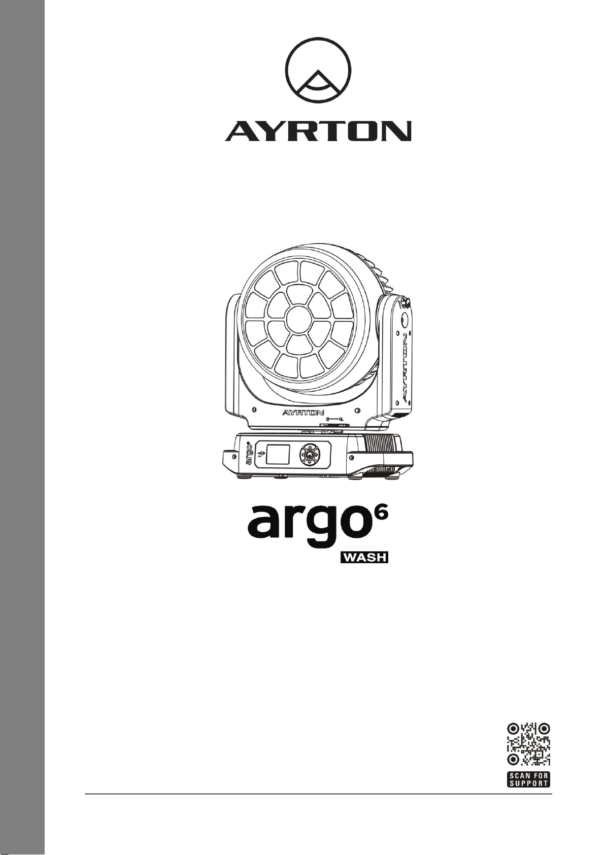
If you use the quick lock cam when rigging the device, make sure the quick lock fasteners
are located in the quick lock holes correctly and securely.
Operate the device only after having familiarized yourself with its functions. Do not permit
operation by persons not qualified for operating the device. Most damage is the result of
unprofessional operation.
Please use the original packaging if the device is to be transported.
The applicable temperature for the device is between -20°C to 45°C.Do not use the device
outside of this temperature range.
The light source contained in this luminaire shall only be replaced by the manufacturer or
his service agent or a similar qualified person.
Important: For safety reasons, please be aware that all modifications to the device are
forbidden. If this device is operated in any way different to the ones described in this manual,
the product may suffer damage and the warranty becomes void. Furthermore, any other
operation may lead to short-circuits, burns, electric shocks etc.

3
2. FEATURES
POWER SUPPLY:
AC100-240V~, 50/60Hz
Power Consumption: 950W
LIGHT SOURCE:
LED: 19 pcs 4 in 1 RGBW LEDs
Extremely long Life: >20,000H
MOVEMENT:
Pan movement: 540º/630ºOptional (16 bit)
Tilt movement: 270º(16 bit)
Advanced moving system: fast, stable and quite, auto X-Y repositioning
COLORS:
Excellent color mixing and rainbow effect
FEATURES:
3 Control channel modes: 26/37/114 channels
2 Operation modes: DMX-512, Master / Slave mode
Fast motorised linear zoom
Strobe effect with 1-25 flashes per second and pulse effect
Dimmer: 0%~100% full range dimming
DISPLAY:
Advanced and convenient full-color LCD
Can be changed 180°reverse to fit for different installation position
SOFTWARE:
Upgrades: fast and convenient through DMX cable with DMX-512 controller
Reset DMX address, reset can all be done by the DMX controller
Running time of fixture on display for reference
OTHER SPEC:
Input signal isolation: guarantees stable signal transmission without interference
Advanced RDM function
WEIGHT
Net weight: 22.7 kg
3. FIXTURE OVERVIEW
1) Lenses Assembly
2) Tilt Lock
3) NFC
4) Display
5) Left-button
6) Center-button
7) Down-button
8) Right-button
9) Up-button
10) Pan Lock
11) Handle
12) Power In
13) Power Out
14) Valve
15) RJ45 In
16) RJ45 Out
17) DMX In
18) DMX Out

4
4. DRAWINGS
4.1.Fixture Dimension
5. INSTALLATION INSTRUCTIONS
5.1.Rigging the device
CAUTION!
PLEASE CONSIDER THE RESPECTIVE NATIONAL NORMS DURING THE
INSTALLATION. THE INSTALLATION MUST ONLY BE CARRIED OUT BY A
QUALIFIED PERSON.
The installation of the effect has to be built and constructed in a way that it can hold 10
times the weight for 1 hour without any harming deformation.
The installation must always be secured with a secondary safety attachment, e.g. an
appropriate safety rope.
Never stand directly below the device when mounting, removing or servicing the fixture.
The operator has to make sure the safety relating and machine technical installations are
approved by an expert before taking the device into operation for the first time.
These installations have to be approved by a skilled person once a year.
Overhead mounting requires extensive experience, including amongst others calculating
working load limits, installation material being used, and periodic safety inspection of all
installation material and the device. If you lack these qualifications, do not attempt the
installation yourself. Improper installation can result in bodily injury.
5.2.Rigging using the omega brackets

5
Important: This step is very important to ensure safe rigging of the fixture.
Fix the clamp to the bracket by tightening the M12 nut and bolt to the bracket through the
Ф13 hole in the middle of the bracket.
Insert the quick-lock fasteners of the first Omega holder into the respective holes on the
bottom of the device. Tighten the quick-lock fasteners fully clockwise.
Install the second Omega holder.
Pull the safety cable through the holes on the bottom of the base and over the trussing
system or another suitable rigging point. Insert the end into the carabiner and tighten the
safety screw.
5.3.RIGGING DRAWINGS
Important:
Overhead rigging requires extensive experience, including (but not limited to) calculating
working load limits, specifying installation/ rigging materials, and periodic safety inspection of
all installation material as well as the device. If you lack these qualifications, do not attempt the
rigging of this device yourself. Improper installation/ rigging can result in serious bodily injury.
1) Omega bracket
2) Clamp
3) Safety rope
4) Quick-lock fastener
Be sure this fixture is kept at
least 0.1m away from any
flammable materials (decoration
etc.).
Always use and install the
supplied safety cable as a safety
measure to prevent accidental
damage and/or injury in the
event the clamp fails.
Rig the projector high enough to
provide clearance for people
who may walk beneath the
beam path or establishing a
restricted access area that
extends beyond the beam
hazard distance.

6
Warnings! Please DO NOT let other external intense lights to shine through the fixture front
lens, it may cause significant internal damages!
When install fixture outdoor at day time (with power off), please make sure that the
fixture front lens is NOT facing the sun.
When use fixture outdoor at day time (with power on), please avoid fixture front lens facing
the sun.
When fixture is on standby outdoor at day time (with power on), please make sure the "sun
protection" mode is ON (default).
WARNING!
After installation in a corrosive environment, the external magnesium alloy covers
surface shall not be in contact with other metal items (keep at least 5mm distance from
other metal items).
This fixture is not designed for permanent use in a marine / corrosive environment.
Following temporary use in such environments, clean fixture with fresh water and dry
before storage.
6. DMX-512 CONTROL CONNECTION
Connect the provided male side of the XLR cable to the female XLR output of your controller
and the female side of the XLR cable to the male XLR input of the device. You can connect
multiple devices together in a serial fashion. The cable needed should be two core, screened
cable with XLR input and output connectors. Please refer to the diagram below.
Address 1 Address 38 Address 75
7. DMX-512 CONNECTION WITH DMX TERMINATOR
For installations where the DMX cable has to run over
a long distance or is in an electrically noisy
environment, such as in a discotheque, it is
recommended to use a DMX terminator. This helps in
preventing corruption of the digital control signal
caused by electrical noise. The DMX terminator is an
XLR plug with a 120 Ω resistor connected between
pins 2 and 3, which is then plugged into the output
(female) XLR socket of the last fixture in the chain.
Please see illustrations below.
8. DEVICE DMX START ADDRESS SELECTION
All fixtures should be given a DMX starting address when using a DMX signal, so that the
correct fixture responds to the correct control signals. This digital starting address is the
channel number from which the fixture starts to “listen” to the digital control information sent out

7
from the DMX controller. The allocation of this starting address is achieved by setting the
correct address number on the display located on the base of the device.
You can set the same starting address for all fixtures or a group of fixtures, or set different
addresses for each fixture individually.
If you set the same address on all devices, all the devices will start to “listen to”the same
control signal from the same channel number. In other words, changing the settings of one
channel will affect all the fixtures simultaneously.
If you set a different address, each unit will start to “listen to” the channel number you have set,
based on the quantity of control channels of the unit. That means changing the settings of one
channel will affect only the selected device.
In the case of the LED moving head, in 37 channel mode, you should set the starting address
of the first unit to 1, the second unit to 38 (37 + 1), the third unit to 75 (37+ 38), and so on.
9. OPERATING INSTRUCTIONS OF THE INTERNAL DMX WIRELESS SYSTEM
9.1 Equipments:
DMX 512 controller, wireless transmitter, and the fixtures with wireless receiver.
9.2 Message from the LED indicator:
1) Rapid flashing red/Green:logging in to a transmitter.
2) Slow flashing Red/Green:Logged on a transmitter and the DMX line is idle (No DMX is
connected to transmitter).
3) Solid Green:Logged on to a transmitter and receiving DMX data.
4) Solid Red:Not logged on to a transmitter (free).
9.3 WDMX in the menu of the fixture:
On a fixture installed with wireless system, in order to switch between wireless control
system and traditional DMX control (with cable), a new menu WDMX is added to the display
board.
ON:(Activate WDMX)
1) When the fixture is on power, and the WDMX is activated to ON status, but did not
connect to the controller and did not log in to the transmitter, the fixture will search for the
DMX signal source. If the fixture is connected to the DMX controller it can be controlled by
DMX controller; if it is log in to the wireless transmitter, it can be controlled by the
Transmitter.
2) When the fixture is power off, and the WDMX is in ON status, if the fixture is connected
to DMX controller. After the fixture is power on, it can be controlled only by the DMX
controller which connected. The fixture can log in the wireless transmitter, and receive only
radio signal from transmitter, but not DMX from the transmitter.
OFF:(De-activate WDMX)
In this status, wireless system is not activated, so the fixture can not log in the transmitter.
REST:(reset WDMX memory)
Can remove the fixture from the connection with the transmitter, the fixture become free
and ready to log in any transmitter.
9.4 Setup the wireless system:

8
1) Connect the transmitter with the DMX controller.
2) To make the fixture installed with wireless receiver log in to the transmitter.
a) Initially, the indicator on the receiver fixture should be in Solid red.
b) Press and hold the configuration button on transmitter for less than 3 seconds the
red/green LEDs on the transmitter and the receiver fixture will flash rapidly for about 5~
10 seconds while the system goes through its setup procedure.
c) Once the receiver fixture is logged in to the transmitter (T1), the fixture with wireless
receiver will keep the memory, even if restart the power, this unit will log in the
transmitter (T1) automatically.
3) Use the DMX 512 to control the fixture
9.5 Remove the receivers from transmitter (T1) and to log in to another transmitter (T2):
Case 1:Remove a receiver:
a) On the control board of the fixture, enter menu to activated the function of REST;
b) The LED for wireless on the fixture should turn to Solid red; the receiver can log out from
the transmitter (T1);
c) press the configuration button on transmitter (T2) for less than 3 second, then the fixture
will start to connect with the transmitter (T2).
Case 2:Remove all receivers from a transmitter (T1) to log in to T2:
a) Press and hold the configuration button on the T1 as least 5 seconds, can clear the
connection with all the fixtures;
b) All the red/green LEDs on the receiver fixtures will turn to Solid red to indicate that the
receivers are unassigned and removed from the transmitter (T1);
c) Press and hold the configuration button on the T2 less then less than 3 second, the
fixtures will connect with the T2.
PS:
1. Please log the receivers out from the transmitter after every job, so that the receivers are
in free un assigned state and ready to be assigned to a transmitter.
2. Do not connect the fixture which is under the communication of wireless system to the
DMX controller, otherwise it will cause interference from the DMX controller.
10. DISPLAY
The Display offers several features:you can set the starting address,run the pre-programmed
program or reset the device.
The main menu is accessed by double clicking -button until the display starts flashing.
Browse through the menu by pressing the -button,-button,-button or -
button .
Press for 2 seconds in order to exit menu, double click for confirm. After accessing
the edit mode,the unit will automatically exit to the main menu after 15 seconds from the last
button press.
When the unit is powered on,if no data signal is connected after 1 minute,then the display will
switch off automatically.

9
Default settings shaded
Address
Main
DMXAddress:xxx
Decimal Universe:xxxxx
Net:xx
Sub-Net:x
Universe:x
Signal
DMXAddress
Decimal Universe
Net
Sub-Net
Universe
DMX/WDMX/Art-Net/sACN
Effect
FollowMain
DMXAddress:xxx
Decimal Universe:xxxxx
Net:xx
Sub-Net:x
Universe:x
Signal
ON/OFF
DMXAddress
Decimal Universe
Net
Sub-Net
Universe
DMX/WDMX/Art-Net/sACN
Pwr led pix
FollowMain
DMXAddress:xxx
Decimal Universe:xxxxx
Net:xx
Sub-Net:x
Universe:x
Signal
ON/OFF
DMXAddress
Decimal Universe
Net
Sub-Net
Universe
DMX/WDMX/Art-Net/sACN
Mode
User Mode
Stand Mode
Basic Mode
Extend Mode
User Mode A
User Mode B
User Mode C
User’s mode to change
channel numbers
Edit User
ModeA/B/C
Max channel
PAN
:
Preset User modes A,B,C
:
Options
Status
No DMX Mode
Sun Protection
Pan Reverse
Tilt Reverse
Pan Degree
Feedback
Init PAN
Init TILT
Pan/Tilt Spd
Hibernation
DMX Output
Close/Hold/Auto
ON/OFF
ON/OFF
ON/OFF
630/540
ON/OFF
ON/OFF
ON/OFF
Fast/Medium/Slow
OFF , 01M~99M
ON/OFF
Auto run if no DMX
Sun Protection
Pan Reverse movement
Tilt Reverse movement
Pan Degree Select
Movement Feedback
Init PAN
Init TILT
Movement Speed
Stand by Mode
DMX Output
Service PIN
Service PIN
RDM UID
Set Ip
Set Mask
DHCP
Cross Load SW
Clr LED Timer
Clr Error Info
Set LED BIN
Password=XXX
Xxxxxx
xxx.xxx.xxx.xxx
xxx.xxx.xxx.xxx
ON/OFF
ON/OFF
ON/OFF
ON/OFF
C14…
Service Password”=050”
RDM UID
Set Ip
Set Mask
DHCP
Cross Load SW
Clr LED Timer
Clr LED Timer
Set LED BIN

10
Fans Control
Fans Speed
Auto
Stage
Silence
Super Silence
Fans Speed select
Constant Fans
ON/OFF
Constant Fans
Disp.Setting
Shutoff Time
Flip Display
Key Lock
DispFlash
02~60m 05m
ON/OFF
ON/OFF
ON/OFF
Display shutoff time
Reverse 180 degree
Key Lock
DispFlash
Temp. C/F
Celsius
Fahrenheit
Temperature switch
between ℃/℉
Initial Pos.
PAN =XXX
Initial effect position
Dim Curve
Square Law
Linear
Dim Curve
Ip From Mac
ON/OFF
Ip From Mac
Refresh Select
1.2K
2.4K
16K
25K
Refresh Select
Defog
OFF/AUTO/ON
Defog
Trigger
DMX Value Disp.
Set to Slave
Auto Program
PAN……
Slave 1, Slave 2, Slave 3
Master/Alone
DMX Value Disp.
Set to Slave
Auto Program
ResetDefault
ON/OFF
Restore factory set.
Reset User
Address
…the same as menu
Address below
DMX address setting
Mode
Stand Mode
Basic Mode
Extend Mode
User Mode A
User Mode B
User Mode C
User’s mode to change
channel numbers
Fans Speed
Auto
Stage
Silence
Super Silence
Fans Speed select
Constant Fans
ON/OFF
Constant Fans
Info
Time Info.
Current Time
Ttl Life Hrs
Last Run Hrs
LED Hours
Timer PIN
Clr Last Run
XXXX(Hours)
XXXX(Hours)
XXXX(Hours)
XXXX(Hours)
Password=XXX
ON/OFF
Temp. Info
XXX℃/℉
Temp. Info
Humidity
x%
Humidity
Fan Info.
xxxx RPM
Fan information

11
Software Ver
V1.0……
Software version
Network
IP,Mask,Mac
Network
Error Info.
Error Record 1
:
Error Info.
SN
xxxxx.....
SN
Test
Home
All
Pan&Tiltr
ZOOM
Reset All
Reset Pan&Tilt
ZOOM
Test Channel
PAN ……
Test function
Manual Ctrl.
PAN =XXX
:
Fine adjustment of the lamp
Calibration
-Password-
PAN
:
Password “050”
Calbrate and adjust the
effects to standard/right
position
Preset
Select Prog.
Prog. Part 1 = Program 1 ~ 10 Program 1
Prog. Part 2 = Program 1 ~ 10 Program 2
Prog. Part 3 = Program 1 ~ 10 Program 3
Select programs to be run
Edit Prog.
Program 1
:
Program 10
Program Test
Step 01=SCxxx
Step 64=SCxxx
Testing program
Program in loop
Save and exit
Edit Scenes
Edit Scene 001
~ Edit Scene 250
Pan,Tilt,……
--Fade Time--
--Secne Time--
Input By Outside
Save and automatically
return manual scenes edit
Scenes Input
XX~XX
Scenes Input
10.1 Address
10.1.1. Main
With this function,you can adjust the desired DMX-address via the Display.
1. Double clicking center button to access main menu.
2. Tap the <Up/Down> button until “Address”is displayed.
3. Double clicking center button to access “Address”,Tap the <Up/Down> button to
select “Main”.
4. Double clicking center button to access “Main”menu,The display will show “DMX
Address:xxx”、“Decimal Universe:xxxxx”、“Net:xx”、“Sub-Net:x”、“Universe:x”、
“Signal”.
5. Double click the center button to confirm or long press the center button to return to
the main menu.
10.1.2. Effect
1. Double clicking center button to access main menu.
2. Tap the <Up/Down> button until “Address”is displayed.
3. Double clicking center button to access “Address”,Tap the <Up/Down> button to
select “Effect”.
4. Double clicking center button to access “Effect”menu,The display will show
“FollowMain”、“DMX Address:xxx”、“Decimal Universe:xxxxx”、“Net:xx”、“Sub-Net:
x”、“Universe:x”、“Signal”.
5. Double click the center button to confirm or long press the center button to return to
the main menu.

12
10.1.3. Pwr led pix
1. Double clicking center button to access main menu.
2. Tap the <Up/Down> button until “Address”is displayed.
3. Double clicking center button to access “Address”,Tap the <Up/Down> button to
select “Pwr led pix”.
4. Double clicking center button to access “Pwr led pix”menu,The display will show
“FollowMain”、“DMX Address:xxx”、“Decimal Universe:xxxxx”、“Net:xx”、“Sub-Net:
x”、“Universe:x”、“Signal”.
5. Double click the center button to confirm or long press the center button to return to
the main menu.
10.2 Mode
10.2.1. User Mode
With this function,you can create user defined channel orders.
1.Double clicking center button to access main menu;Tap the <Up/Down> button until
“Mode”is displayed. Double clicking center button to enter.
2.Press <Up/Down>,the display will show “User Mode”.
3.Double clicking center button to enter.
4.When in “Extend Mode”,Press <Up/Down> button to select “Basic Mode”,“Stand
Mode”,“Extend Mode”,“User Mode A”,“User Mode B” and “User Mode C”.
5.Double click the center button to confirm or long press the center button to return to
the main menu.
10.2.2. Edit User Mode
With this function,you can adjust the rest user defined channel order.
1.Double clicking center button to access main menu;Tap the <Up/Down> button until
“Mode”is displayed. Double clicking center button to enter.
2.Press <Up/Down>,the display will show “Edit User Mode”.
3.Double clicking center button to enter.
4.Set up “Max Channel=xxx” and select channel value.
5.Set up “Mode B” and “Mode C” by the same way.
6.Double click the center button to confirm or long press the center button to return to
the main menu.
10.3 Options
10.3.1. Status
No DMX Status
With this function,when the drive is not DMX signal,it runs automatism,close,hold and
music,the default is hold.
1. Double clicking center button to access main menu.
2. Tap the <Up/Down> button until “Options”is displayed.
3. Double clicking center button to access “Options”,Tap the <Up/Down> button to select
“Status”.
4. Double clicking center button to access “Status” menu,Tap the <Up/Down> button to
select “No DMX Status”.
5. Double clicking center button to access “No DMX Status”,The display will show
“Hold”,Tap the <Up/Down> button to select “Close”,“Auto”.
6. Double click the center button to confirm or long press the center button to return to
the main menu.
Sun Protection

13
1. Double clicking center button to access main menu.
2. Tap the <Up/Down> button until “Options”is displayed.
3. Double clicking center button to access “Options”,Tap the <Up/Down> button to select
“Status”.
4. Double clicking center button to access “Status” menu,Tap the <Up/Down> button to
select “Sun Protection”.
5. Double clicking center button to access “Sun Protection”,The display will show
“OFF”,Tap the <Up/Down> button to select “ON”.
6. Double click the center button to confirm or long press the center button to return to
the main menu.
Pan Reverse
With this function you can reverse the Pan-movement.
1. Double clicking center button to access main menu.
2. Tap the <Up/Down> button until “Options ”is displayed.
3. Double clicking center button to access “Options”,Tap the <Up/Down> button to select
“Status”.
4. Double clicking center button to access “Status” menu,Tap the <Up/Down> button to
select “Pan Reverse”.
5. Double clicking center button to access “Pan Reverse”,The display will show “OFF”,
Tap the <Up/Down> button to select “NO”.
6. Double click the center button to confirm or long press the center button to return to
the main menu.
Tilt Reverse
With this function you can reverse the Tilt-movement.
1. Double clicking center button to access main menu.
2. Tap the <Up/Down> button until “Options”is displayed.
3. Double clicking center button to access “Options”,Tap the <Up/Down> button to select
“Status”.
4. Double clicking center button to access “Status” menu,Tap the <Up/Down> button to
select “Tilt Reverse”.
5. Double clicking center button to access “Tilt Reverse”,The display will show “OFF”,
Tap the <Up/Down> button to select “NO”.
6. Double click the center button to confirm or long press the center button to return to
the main menu.
Pan Degree
With this function,you can select pan degree for 630 or 540.
1. Double clicking center button to access main menu.
2. Tap the <Up/Down> button until “Options”is displayed.
3. Double clicking center button to access “Options”,Tap the <Up/Down> button to select
“Status”.
4. Double clicking center button to access “Status” menu,Tap the <Up/Down> button to
select “Pan Degree”.
5. Double clicking center button to access “Pan Degree”,The display will show “540”,
Tap the <Up/Down> button to select “630”.
6. Double click the center button to confirm or long press the center button to return to
the main menu.
Feedback
With this function,you can feedback switch of pan movement or tilt movement.
1. Double clicking center button to access main menu.
2. Tap the <Up/Down> button until “Options”is displayed.

14
3. Double clicking center button to access “Options”,Tap the <Up/Down> button to select
“Status”.
4. Double clicking center button to access “Status” menu,Tap the <Up/Down> button to
select “Feedback”.
5. Double clicking center button to access “Feedback”,The display will show “ON”,Tap
the <Up/Down> button to select “OFF”.
6. Double click the center button to confirm or long press the center button to return to
the main menu.
Init PAN
With this function,you can feedback switch of pan movement or tilt movement.
1. Double clicking center button to access main menu.
2. Tap the <Up/Down> button until “Options”is displayed.
3. Double clicking center button to access “Options”,Tap the <Up/Down> button to select
“Status”.
4. Double clicking center button to access “Status” menu,Tap the <Up/Down> button to
select “Init PAN”.
5. Double clicking center button to access “Init PAN”,The display will show “ON”,Tap the
<Up/Down> button to select “OFF”.
6. Double click the center button to confirm or long press the center button to return to
the main menu.
Init TILT
With this function,you can feedback switch of pan movement or tilt movement.
1. Double clicking center button to access main menu.
2. Tap the <Up/Down> button until “Options”is displayed.
3. Double clicking center button to access “Options”,Tap the <Up/Down> button to select
“Status”.
4. Double clicking center button to access “Status” menu,Tap the <Up/Down> button to
select “Init TILT”.
5. Double clicking center button to access “Init TILT”,The display will show “ON”,Tap the
<Up/Down> button to select “OFF”.
6. Double click the center button to confirm or long press the center button to return to
the main menu.
Pan/Tilt Spd
With this function,you can select scan mode from “Fast”,“Medium”,“Slow”.
1. Double clicking center button to access main menu.
2. Tap the <Up/Down> button until “Options”is displayed.
3. Double clicking center button to access “Options”,Tap the <Up/Down> button to select
“Status”.
4. Double clicking center button to access “Status” menu,Tap the <Up/Down> button to
select “Pan/Tilt Spd”.
5. Double clicking center button to access “Pan/Tilt Spd”,The display will show “Fast”,
Tap the <Up/Down> button to select “Fast”,“Medium”,“Slow”.
6. Double click the center button to confirm or long press the center button to return to
the main menu.
Hibernation
The device and step motors will be power off if the fixture stay without DMX signal for 15
mins (Factory default).And the fixture will be reset before working once it receive DMX
signal again.
1. Double clicking center button to access main menu.
2. Tap the <Up/Down> button until “Options”is displayed.

15
3. Double clicking center button to access “Options”,Tap the <Up/Down> button to select
“Status”.
4. Double clicking center button to access “Status” menu,Tap the <Up/Down> button to
select “Hibernation”.
5. Double clicking center button to access “Hibernation”,The display will show “OFF”,
Tap the <Up/Down> button to select“01M”,“02M” . . . “99M”.
6. Double click the center button to confirm or long press the center button to return to
the main menu.
DMX Output
1. Double clicking center button to access main menu.
2. Tap the <Up/Down> button until “Options”is displayed.
3. Double clicking center button to access “Options”,Tap the <Up/Down> button to select
“Status”.
4. Double clicking center button to access “Status” menu,Tap the <Up/Down> button to
select “DMX Output”.
5. Double clicking center button to access “DMX Output”,The display will show “OFF”,
Tap the <Up/Down> button to select “ON”.
6. Double click the center button to confirm or long press the center button to return to
the main menu.
10.3.2. Service PIN
Password
The Password for this function is“050”.
RDM UID
1. Double clicking center button to access main menu.
2. Tap the <Up/Down> button until “Options”is displayed.
3. Double clicking center button to access “Options”,Tap the <Up/Down> button to select
“Service PIN”.
4. Double clicking center button to access “Service PIN” menu,Tap the <Up/Down>
button to select “RDM UID”.
5. Double clicking center button to access “RDM UID”,The display will show “Xxxxxx”.
6. Double click the center button to confirm or long press the center button to return to
the main menu.
Set IP
1. Double clicking center button to access main menu.
2. Tap the <Up/Down> button until “Options”is displayed.
3. Double clicking center button to access “Options”,Tap the <Up/Down> button to select
“Service PIN”.
4. Double clicking center button to access “Service PIN” menu,Tap the <Up/Down>
button to select “Set IP”.
5. Double clicking center button to access “Set IP” ,The display will show
“XXX.XXX.XXX.XXX”.
6. Double click the center button to confirm or long press the center button to return to
the main menu.
Set Mask IP
1. Double clicking center button to access main menu.
2. Tap the <Up/Down> button until “Options”is displayed.
3. Double clicking center button to access “Options”,Tap the <Up/Down> button to select
“Service PIN”.
4. Double clicking center button to access “Service PIN” menu,Tap the <Up/Down>

16
button to select “Set Mask IP”.
5. Double clicking center button to access “Set Mask IP”,The display will show
“XXX.XXX.XXX.XXX”.
6. Double click the center button to confirm or long press the center button to return to
the main menu.
DHCP
1. Double clicking center button to access main menu.
2. Tap the <Up/Down> button until “Options”is displayed.
3. Double clicking center button to access “Options”,Tap the <Up/Down> button to select
“Service PIN”.
4. Double clicking center button to access “Service PIN” menu,Tap the <Up/Down>
button to select “DHCP”.
5. Double clicking center button to access “DHCP”,The display will show “OFF”,Tap the
<Up/Down> button to select “ON”.
6. Double click the center button to confirm or long press the center button to return to
the main menu.
Cross Load SW
1. Double clicking center button to access main menu.
2. Tap the <Up/Down> button until “Options”is displayed.
3. Double clicking center button to access “Options”,Tap the <Up/Down> button to select
“Service PIN”.
4. Double clicking center button to access “Service PIN” menu,Tap the <Up/Down>
button to select “Cross Load SW”.
5. Double clicking center button to access “Cross Load SW”,The display will show
“OFF”,Tap the <Up/Down> button to select “ON”.
6. Double click the center button to confirm or long press the center button to return to
the main menu.
Clr LED Timer
1. Double clicking center button to access main menu.
2. Tap the <Up/Down> button until “Options”is displayed.
3. Double clicking center button to access “Options”,Tap the <Up/Down> button to select
“Service PIN”.
4. Double clicking center button to access “Service PIN” menu,Tap the <Up/Down>
button to select “Clr LED Timer”.
5. Double clicking center button to access “Clr LED Timer”,The display will show “OFF”,
Tap the <Up/Down> button to select “ON”.
6. Double click the center button to confirm or long press the center button to return to
the main menu.
Clr Error Info
1. Double clicking center button to access main menu.
2. Tap the <Up/Down> button until “Options”is displayed.
3. Double clicking center button to access “Options”,Tap the <Up/Down> button to select
“Service PIN”.
4. Double clicking center button to access “Service PIN” menu,Tap the <Up/Down>
button to select “Clr Error Info”.
5. Double clicking center button to access “Clr Error Info”,The display will show “OFF”,
Tap the <Up/Down> button to select “ON”.
6. Double click the center button to confirm or long press the center button to return to
the main menu.

17
Set LED BIN
1. Double clicking center button to access main menu.
2. Tap the <Up/Down> button until “Options”is displayed.
3. Double clicking center button to access “Options”,Tap the <Up/Down> button to select
“Service PIN”.
4. Double clicking center button to access “Service PIN” menu,Tap the <Up/Down>
button to select “Set LED BIN”.
5. Double clicking center button to access “Set LED BIN”,The display will show “C14”,
“...”.
6. Double click the center button to confirm or long press the center button to return to
the main menu.
10.3.3. Fans Control
Fans Speed
With this function you can set the speed of the running fans. The selections have Auto、
Stage、Silence and Super Silence.
1.Double clicking center button to access main menu.
2.Tap the <Up/Down> button until “Options”is displayed.
3.Double clicking center button to access “Options”,Tap the <Up/Down> button to
select “Fans Control”.
4.Double clicking center button to access “Fans Control”menu,Tap the <Up/Down>
button to select “Fans Speed”.
5.Double clicking center button to access “Fans Speed”,The display will show “Auto”,
Tap the <Up/Down> button to select “Stage”,“Silence”,“Super Silence”.
6.Double click the center button to confirm or long press the center button to return to
the main menu.
Constant Fans
1.Double clicking center button to access main menu.
2.Tap the <Up/Down> button until “Options”is displayed.
3.Double clicking center button to access “Options”,Tap the <Up/Down> button to
select “Fans Control”.
4.Double clicking center button to access “Fans Control”menu,Tap the <Up/Down>
button to select “Constant Fans”.
5.Double clicking center button to access “Constant Fans”,The display will show
“OFF”,Tap the <Up/Down> button to select “ON”.
6.Double click the center button to confirm or long press the center button to return to
the main menu.
10.3.4. Disp. Setting
Shut off Time
With this function you can shut off the LCD display after 2 to 60 minutes. The default is 5
minutes.
1.Double clicking center button to access main menu.
2.Tap the <Up/Down> button until “Options”is displayed.
3.Double clicking center button to access “Options”,Tap the <Up/Down> button to
select “Display Setting”.
4.Double clicking center button to access “Display Setting” menu,Tap the <Up/Down>
button to select “Shut off Time”.
5.Double clicking center button to access “Shut off Time”,The display will show “05m”,
Tap the <Up/Down> button to select“02~60m”.
6.Double click the center button to confirm or long press the center button to return to
the main menu.

18
Flip Display
With this function you can rotate the display by 180°.
1.Double clicking center button to access main menu.
2.Tap the <Up/Down> button until “Options”is displayed.
3.Double clicking center button to access “Options”,Tap the <Up/Down> button to
select “Display Setting”.
4.Double clicking center button to access “Display Setting” menu,Tap the <Up/Down>
button to select “Flip Display”.
5.Double clicking center button to access “Flip Display”,The display will show “OFF”,
Tap the <Up/Down> button to select “ON”.
6.Double click the center button to confirm or long press the center button to return to
the main menu.
Key Lock
With this function you can activate the automatic key lock function. If this function is
activated,the keys will be locked automatically after exiting the edit mode for 15 seconds.
keeping press the <MODE/ESC> key for 3seconds if you do not need this function.
1.Double clicking center button to access main menu.
2.Tap the <Up/Down> button until “Options”is displayed.
3.Double clicking center button to access “Options”,Tap the <Up/Down> button to
select “Display Setting”.
4.Double clicking center button to access “Display Setting” menu,Tap the <Up/Down>
button to select “Key Lock”.
5.Double clicking center button to access “Key Lock”,The display will show “OFF”,Tap
the <Up/Down> button to select “ON”.
6.Double click the center button to confirm or long press the center button to return to
the main menu.
DispFlash
With this function you can the entire display to be flipped by 180°to allow for better view
when the fixture is hung from truss or a ceiling. This function is disabled as default.
1.Double clicking center button to access main menu.
2.Tap the <Up/Down> button until “Options”is displayed.
3.Double clicking center button to access “Options”,Tap the <Up/Down> button to
select “Display Setting”.
4.Double clicking center button to access “Display Setting” menu,Tap the <Up/Down>
button to select “DispFlash”.
5.Double clicking center button to access “DispFlash”,The display will show “OFF”,Tap
the <Up/Down> button to select “ON”.
6.Double click the center button to confirm or long press the center button to return to
the main menu.
10.3.5. Temperature C/F
With this function you can display the temperature in Celsius or Fahrenheit.
1.Double clicking center button to access main menu.
2.Tap the <Up/Down> button until “Options”is displayed.
3.Double clicking center button to access “Options”,Tap the <Up/Down> button to
select “Temperature C/ F”.
4.Double clicking center button to access “Temperature C/ F”,The display will show
“Celsius”,Tap the <Up/Down> button to select “Fahrenheit”.
5.Double click the center button to confirm or long press the center button to return to
the main menu.
Table of contents
Other Ayrton Light Fixture manuals
Popular Light Fixture manuals by other brands

Emos
Emos CHERRY ZY1946 manual

LEGRAND
LEGRAND Wattstopper Vantage Miro MRP6 installation instructions

Quick
Quick PLT 300 Manual of use and maintenance

Cooper Lighting
Cooper Lighting Metalux I5455 Specifications

Cooper Lighting
Cooper Lighting PM613OB Specification sheet

Williams-Sonoma
Williams-Sonoma HOOK WINFIELD DOUBLE SWIVEL Assembly instructions