ADJUSTABLE WELL STAR™
Installation Instructions
RELEASE DATE
9-8-15
REFERENCE NUMBER
INS000967
40429 Brickyard Drive • Madera, CA 93636 • USA
559.438.5800 • FAX 559.438.5900
B-K LIGHTING
THIS DOCUMENT CONTAINS PROPRIETARY INFORMATION OF B-K LIGHTING, INC. AND ITS RECEIPT OR POSSESSION DOES NOT CONVEY ANY RIGHTS TO REPRODUCE, DISCLOSE ITS CONTENTS, OR TO MANUFACTURE, USE OR SELL ANYTHING IT MAY
DESCRIBE. REPRODUCTION, DISCLOSURE OR USE WITHOUT SPECIFIC WRITTEN AUTHORIZATION OF B-K LIGHTING, INC. IS STRICTLY FORBIDDEN.
TOOLS
REQUIRED:
By Others
1/8” Allen Wrench
Waterproof Wire Connectors
Phillips Screwdriver
(200mm)
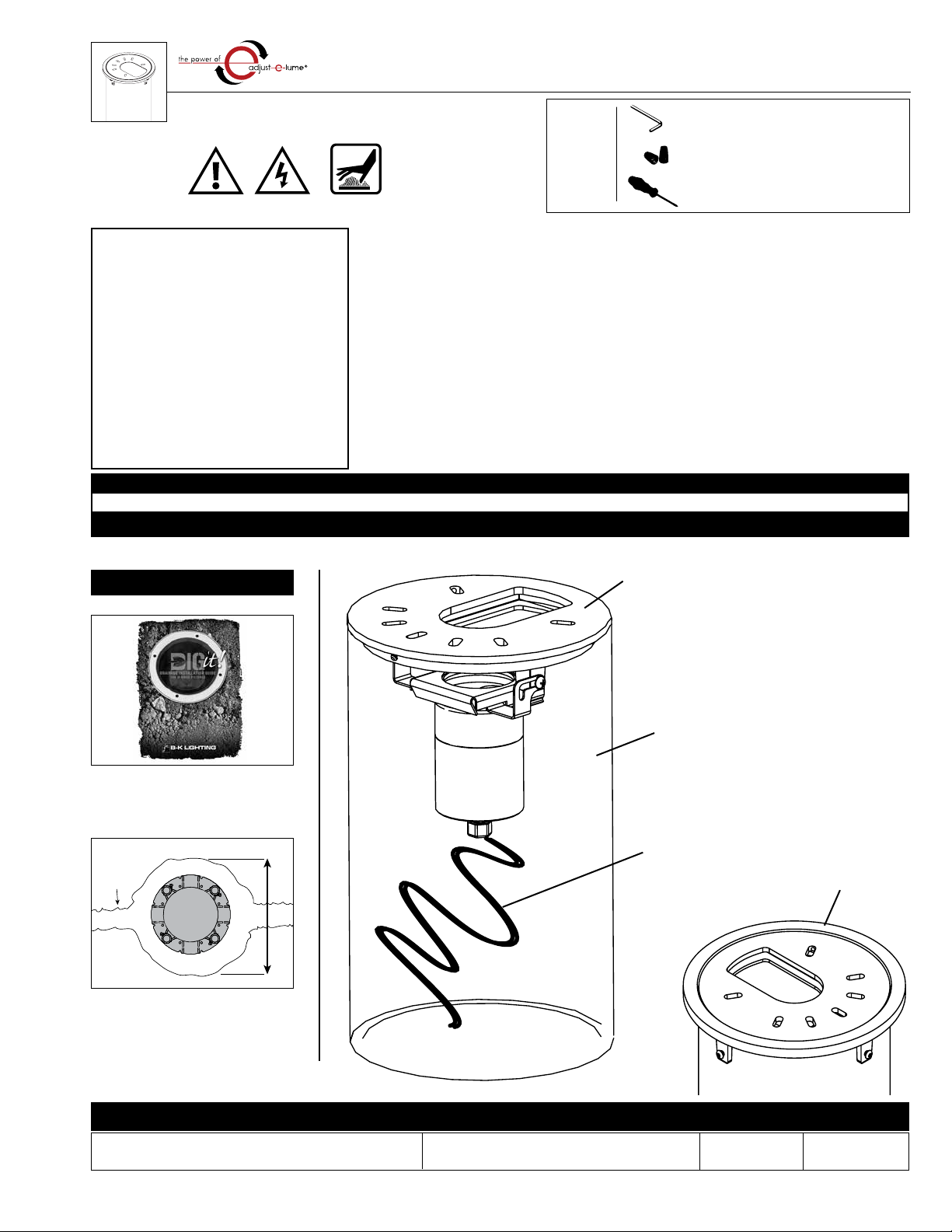
7 7/8 Dia.
Standard Composite
Housing with four
Pour Collar
Adjustable Well Star
Screws
Stainless Steel
Housing
Concrete
Cast Brass
Adjustable Well Star
Collar Attached to
Regress Allow for
Flush Mounting of
Adjustable Well
Star Faceplate
(6mm)
1/4" Regress
12 1/8"
(308mm)
12"
(302mm)
Positive Locking Screw
Stainless Steel Vertical
Aiming Bracket,with
(168mm)
Dia.
6 5/8"
35
Tampered Glass Lens
Cast Brass Cover
(Finish as Specied)
6 5/8" Dia.
(168mm)
6 5/8" Dia.
(168mm)
.3125" wall
PVC Housing
Patent Pending
Adjust-e-Lume®
This set of instructions
works for:
AW - Adjustable
Well Star™
Cast Brass Faceplate
Composite Housing
5’ of 18 gauge wire
Cast Brass Concrete
Pour Collar Option
TECHNOLOGY
with
Hot Surface
Warning Low Voltage
• Product must be installed by a qualified person in a manner
consistent with its intended use and in compliance with the
National Electrical Code, Canadian Electrical Code, and all Local
and Provincial Codes.
• Follow product label information and instructions.
• Qualified Personnel must perform all servicing or relamping of
this product.
• Before wiring to power supply and during servicing or relamping,
turn off power at fuse or circuit breaker before service.
• The use of accessory equipment not recommended by the
manufacturer or installed contrary to instructions may cause an
unsafe condition. The use of damaged components may cause
an unsafe condition and void product warranty.
IMPORTANT SAFETY INFORMATION - READ, FOLLOW, AND SAVE ALL SAFETY
AND INSTALLATION INSTRUCTIONS
• Do not block light emanating from product in whole or part,
as this may cause an unsafe condition.
• Never operate the fixture with missing or damaged lens.
Lens must be cleaned on regular basis.
• Entire fixture may become extremely hot. Do not touch hot
lens or fixture body. Do not touch the lamp at any time. Use
a clean, dry, soft cloth to handle the lamp. Oil from skin may
damage the lamp and cause it to rupture.
• Replace lamp only with correct wattage and type of lamp
marked on fixture label.
• All gaskets, O-rings and sealing surfaces must be kept clean
during installation and service; failure to do this may cause an
unsafe condition and void product warranty.
INSTRUCTIONS PERTAINING TO
A RISK OF FIRE, OR INJURY TO
PERSONS IMPORTANT SAFETY
INSTRUCTIONS
Lighted lamp is HOT!
WARNING - To reduce the risk of FIRE OR INJURY TO PERSONS:
Turn off/unplug and allow to cool before replacing lamp.
Lamp gets HOT quickly! Contact only switch/plug when
turning on.
Do not touch hot lens, guard, or enclosure (see diagram/
picture).
Keep lamp away from materials that may burn.
Do no touch the lamp at any time. Use a soft cloth. Oil
from skin may damage lamp.
Do not operate the luminaire fitting with a missing or
damaged shield.
SAVE THESE INSTRUCTIONS
· Suitable for wet locations · Suitable for recessed in ground locations
IMPORTANT LISTINGS AND CERTIFICATIONS
& Low Voltage
IMPORTANT SAFETY INFORMATION - READ, FOLLOW, AND SAVE THESE INSTALLATION INSTRUCTIONS
A. Determine Soil Type by referencing
DIG-IT Guide. Prep soil according to
DIG-IT Guide.
Soil Prep
B. Excavate a hole to the necessary
dimensions for fixture placement
according to lighting plan.
Conduit
trench
Proper soil preparation is recommended before installation. See the DIG-IT guide at www.bklighting.com/dig-it for more information.


