manuals.online logo
Brands
  1. Home
  2. •
  3. Brands
  4. •
  5. B-K lighting
  6. •
  7. Landscape Lighting
  8. •
  9. B-K lighting Precision2 HP2 Series User manual

B-K lighting Precision2 HP2 Series User manual

RELEASE DATE
6-28-13
REFERENCE NUMBER
INS001129
40429 Brickyard Drive • Madera, CA 93636 • USA
559.438.5800 • FAX 559.438.5900
www.bklighting.com • [email protected]
B-K LIGHTING
THIS DOCUMENT CONTAINS PROPRIETARY INFORMATION OF B-K LIGHTING, INC. AND ITS RECEIPT OR POSSESSION DOES NOT CONVEY ANY RIGHTS TO REPRODUCE, DISCLOSE ITS CONTENTS, OR TO MANUFACTURE, USE OR SELL ANYTHING IT MAY
DESCRIBE. REPRODUCTION, DISCLOSURE OR USE WITHOUT SPECIFIC WRITTEN AUTHORIZATION OF B-K LIGHTING, INC. IS STRICTLY FORBIDDEN.
Warning High Voltage Hot Surface
Silicone filled
wire nuts
Silicone ‘O’ Ring
Heat Sink
Patented
Stability
Flange
3/32” Allen Wrench
Phillips screwdriver
Level
Hammer
NEEDED
FOR
INSTALLATION:
By Others
IMPORTANT SAFETY INFORMATION - READ, FOLLOW, AND SAVE THESE INSTALLATION INSTRUCTIONS
Conduit
trench 18”
Dia.
A. Determine Soil Type by referencing
DIG-IT Guide.
B. Dig hole 18” wide and 20” deep.
C. Prep soil according to DIG-IT Guide.
Soil Prep
Quick
Disconnects
• Product must be installed by a qualified person in a manner
consistent with its intended use and in compliance with the
National Electrical Code, Canadian Electrical Code, and all Local
and Provincial Codes.
• Follow product label information and instructions.
• Qualified Personnel must perform all servicing or relamping of
this product.
• Before wiring to power supply and during servicing or
relamping, turn off power at fuse or circuit breaker before
service.
• The use of accessory equipment not recommended by the
manufacturer or installed contrary to instructions may cause an
unsafe condition. The use of damaged components may cause
IMPORTANT SAFETY INFORMATION - READ, FOLLOW, AND SAVE ALL SAFETY
AND INSTALLATION INSTRUCTIONS
an unsafe condition and void product warranty.
• Do not block light emanating from product in whole or part,
as this may cause an unsafe condition.
• Never operate the fixture with missing or damaged lens.
Lens must be cleaned on regular basis.
• Entire fixture may become extremely hot. Do not touch hot
lens or fixture body. Do not touch the lamp at any time. Use
a clean, dry, soft cloth to handle the lamp. Oil from skin may
damage the lamp and cause it to rupture.
• Replace lamp only with correct wattage and type of lamp
marked on fixture label.
• All gaskets, o-rings and sealing surfaces must be kept clean
during installation and service; failure to do this may cause
an unsafe condition and void product warranty.
INSTRUCTIONS PERTAINING TO
A RISK OF FIRE, OR INJURY TO
PERSONS IMPORTANT SAFETY
INSTRUCTIONS
Lighted lamp is HOT!
WARNING - To reduce the risk of FIRE OR INJURY TO PERSONS:
Turn off/unplug and allow to cool before replacing lamp.
Lamp gets HOT quickly! Contact only switch/plug when
turning on.
Do not touch hot lens, guard, or enclosure (see diagram/
picture).
Keep lamp away from materials that may burn.
Do no touch the lamp at any time. Use a soft cloth. Oil
from skin may damage lamp.
Do not operate the luminaire fitting with a missing or
damaged shield.
SAVE THESE INSTRUCTIONS
Proper soil preparation is recommended before installation. See the DIG-IT guide at www.bklighting.com/dig-it for more information.
Patented
Hydro-Lock™
Plate
Driver Tray
Fixture Housing
Accessory Holder
Optic
HP2
powered by
HP2 Faceplate
Wiring Diagram
COM
GROUND
LINE
COM
GROUND
LINE
HydroLock Plate
RELEASE DATE
6-28-13
REFERENCE NUMBER
INS001129
40429 Brickyard Drive • Madera, CA 93636 • USA
559.438.5800 • FAX 559.438.5900
www.bklighting.com • [email protected]
B-K LIGHTING
Fixture Installation
1. Remove temporary cover. 2. Make connections using silicone filled wire
nuts (provided) to leads on the bottom of
Patented Hydro-Lock™Barrier Plate Assembly.
See wiring diagram.
HP2
powered by
1. Connect branch conduit connectors (By Others)
to the junction box using either the threaded
conduit entries on the bottom of the junction
box or through holes drilled into the sides of the
junction box.
2. Place housing in hole. Align junction box in the
path of the conduit trench.
3. Insert (4) pieces of ½” EMT/Conduit longer than
the height of the hole through the Patented
Stability Flange™. Hammer substrate into
ground until housing is secure.
Leave sufficient clearance to elevate housing
to finished grade.
Flush with finished grade
4. Raise the top of the housing flush to finished
grade using EMT/Conduit for support. Use a
level to aid in housing installation. If housing
comes with a concrete pour collar (CPC) raise
housing flush to finished grade.
5. When housing is level, tighten screws on
Patented Stability Flange™ to secure housing to
EMT/Conduit. Remove excess EMT as needed.
6. Connect the conduit to the conduit connectors.
7. Per DIG-IT Guide, backfill the gap between the
bottom of housing and bottom of hole with
sand for drainage.
8. Fill and tamp soil to the appropriate height
leaving room for sod, pavers, concrete, etc. to
be level with the top of the temporary cover.
Housing Installation for HP2
Side Flats
RELEASE DATE
6-28-13
REFERENCE NUMBER
INS001129
40429 Brickyard Drive • Madera, CA 93636 • USA
559.438.5800 • FAX 559.438.5900
www.bklighting.com • [email protected]
B-K LIGHTING
Fixture Installation (cont.)
3. Wipe O-ring clean of debris on Patented Hydro-
Lock™ Barrier Plate. Install Patented Hydro-Lock™
Barrier Plate by aligning keyholes with dome-
topped fasteners at the bottom of the housing
and while grasping handle; push down on
Patented Hydro-Lock™ Barrier Plate until firmly
seated.
4. Turn Hydro-Lock™
Barrier Plate clockwise ¼” to
lock.
Patented Hydro-Lock™ Barrier Plate must be
completely seated to ensure proper seal or
water may intrude. This step must be done
as stated or you will void your warranty.
5. Connect transformer assembly to Patented
Hydro-Lock™ Barrier Plate with quick
disconnect.
6. Attach driver assembly to housing by aligning
keyhole notch under one (1) of three (3) #8
screw heads. Tighten screw heads with Philips
screw driver.
8.
Place optical assembly in housing, resting
the optilock on the pins provided inside the
housing. Aim fixture by adjusting optilock with
Philips screw driver.
9. Carefully place O-ring into the groove on top of
housing, keep free of dirt and debris. Dirt and
debris may allow water entry into fixture.
This step must be done as stated or you will
void your warranty.
10. Secure faceplate assembly to housing with (5)
#10 socket head screws as provided on faceplate
with 3/32” Allen wrench. Hand tighten screws in
a cross pattern to 25 in-lbs. to create proper seal.
7. Attach optical assembly to installed driver
assembly with quick disconnect.
HP2
powered by

Other manuals for Precision2 HP2 Series

4

Other B-K lighting Landscape Lighting manuals

B-K lighting MCKINLEY Series User manual

B-K lighting

B-K lighting MCKINLEY Series User manual

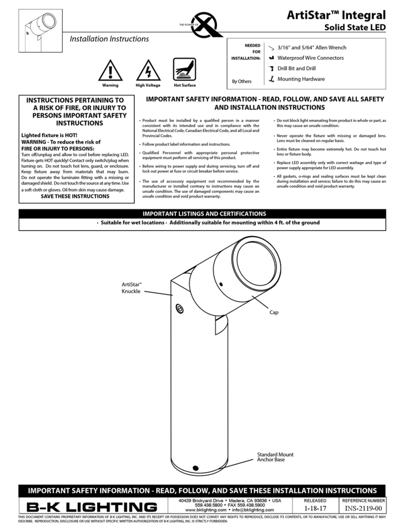
B-K lighting ArtiStar Integral User manual

B-K lighting

B-K lighting ArtiStar Integral User manual

B-K lighting HUME User manual

B-K lighting

B-K lighting HUME User manual

B-K lighting ALPS Series User manual

B-K lighting

B-K lighting ALPS Series User manual

B-K lighting SS User manual

B-K lighting

B-K lighting SS User manual

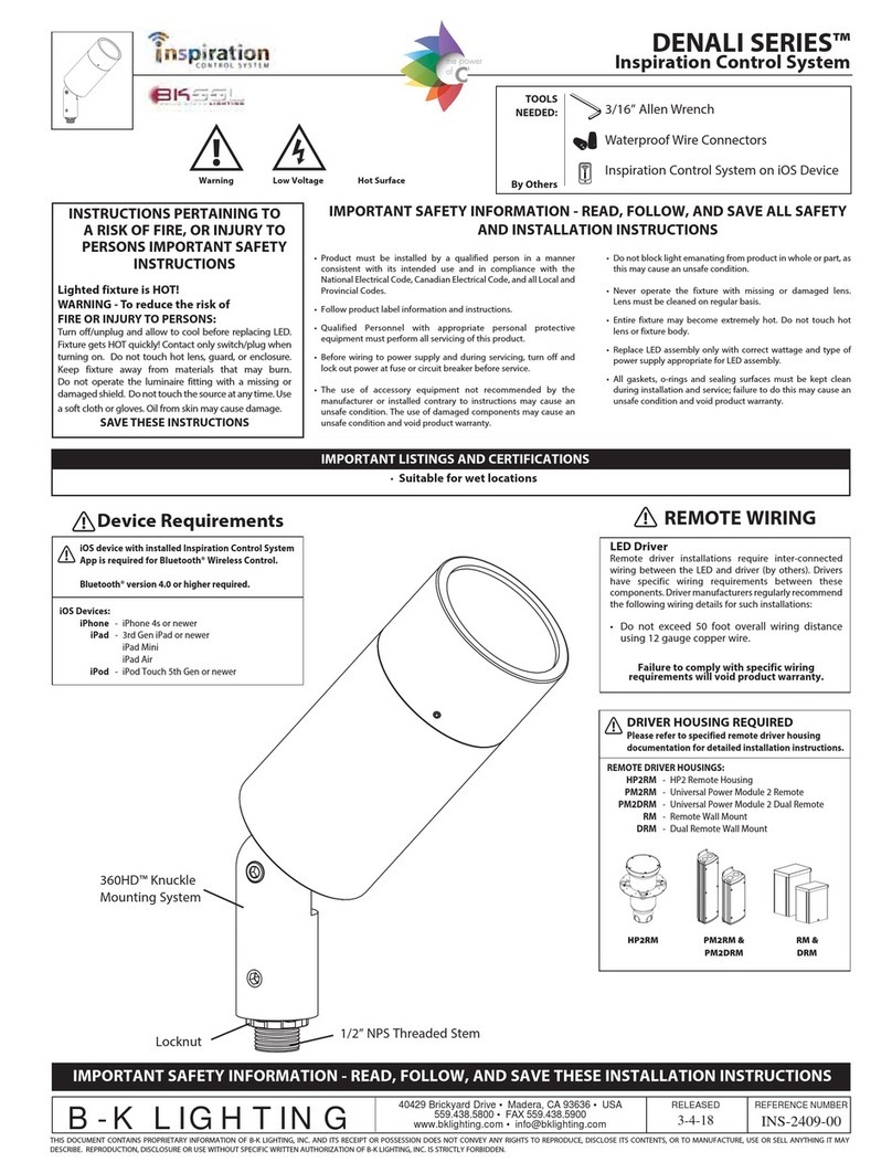
B-K lighting Denali Series User manual

B-K lighting

B-K lighting Denali Series User manual

B-K lighting UL Series User manual

B-K lighting

B-K lighting UL Series User manual

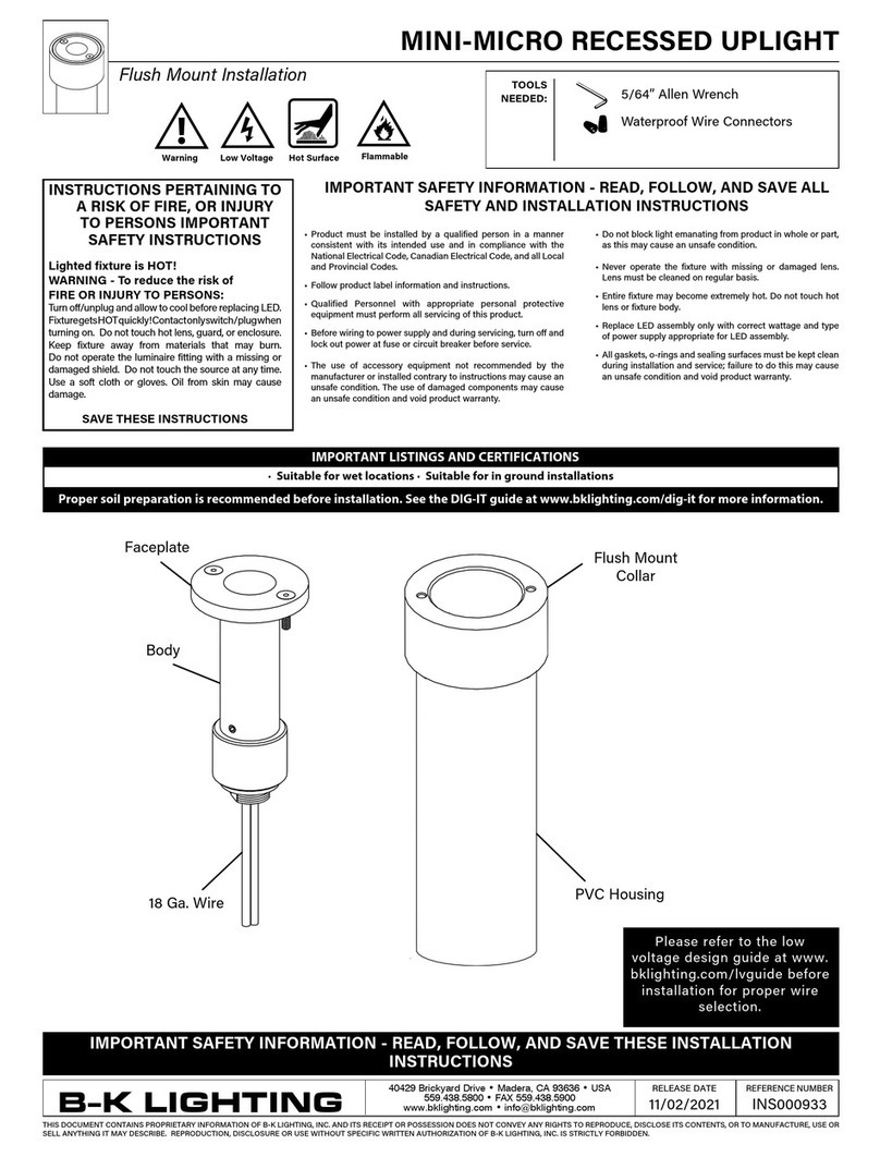
B-K lighting MINI-MICRO User manual

B-K lighting

B-K lighting MINI-MICRO User manual

B-K lighting ADJUSTABLE WELL STAR User manual

B-K lighting

B-K lighting ADJUSTABLE WELL STAR User manual

B-K lighting Denali Series User manual

B-K lighting

B-K lighting Denali Series User manual

B-K lighting ArtiStar Series User manual

B-K lighting

B-K lighting ArtiStar Series User manual

B-K lighting UL Series User manual

B-K lighting

B-K lighting UL Series User manual

Popular Landscape Lighting manuals by other brands

Malibu Boats CS200C instructions

Malibu Boats

Malibu Boats CS200C instructions

LIGMAN CAPSULE 4 CA-30597 installation manual

LIGMAN

LIGMAN CAPSULE 4 CA-30597 installation manual

Faro GRUND 13W installation instructions

Faro

Faro GRUND 13W installation instructions

LIGMAN AMOS 4 installation manual

LIGMAN

LIGMAN AMOS 4 installation manual

AMP Lighting AFL-401-LI-A-BZ Series Installation & maintenance guide

AMP Lighting

AMP Lighting AFL-401-LI-A-BZ Series Installation & maintenance guide

LIGMAN NYB-80241 installation manual

LIGMAN

LIGMAN NYB-80241 installation manual

Pelican 9440 user manual

Pelican

Pelican 9440 user manual

AL Tech AE-L-ALAS-35 manual

AL Tech

AL Tech AE-L-ALAS-35 manual

Inlite LIV LOW manual

Inlite

Inlite LIV LOW manual

Cooper Lighting Lexington LXD70SR2334 Specification sheet

Cooper Lighting

Cooper Lighting Lexington LXD70SR2334 Specification sheet

SIGNIFY Keene Stonco Mounting instructions

SIGNIFY

SIGNIFY Keene Stonco Mounting instructions

LIGMAN NYB-80101 installation manual

LIGMAN

LIGMAN NYB-80101 installation manual

LIGMAN FORREY 17 installation manual

LIGMAN

LIGMAN FORREY 17 installation manual

Saxby Lighting Canillo 67699 instruction manual

Saxby Lighting

Saxby Lighting Canillo 67699 instruction manual

LIGMAN VIENNA 2 installation manual

LIGMAN

LIGMAN VIENNA 2 installation manual

LIGMAN FORREY 2 installation manual

LIGMAN

LIGMAN FORREY 2 installation manual

Cooper Lighting Pole Mount Icon installation instructions

Cooper Lighting

Cooper Lighting Pole Mount Icon installation instructions

for Living 052-9426-0 instruction manual

for Living

for Living 052-9426-0 instruction manual

manuals.online logo
manuals.online logoBrands
  • About & Mission
  • Contact us
  • Privacy Policy
  • Terms and Conditions

Copyright 2025 Manuals.Online. All Rights Reserved.