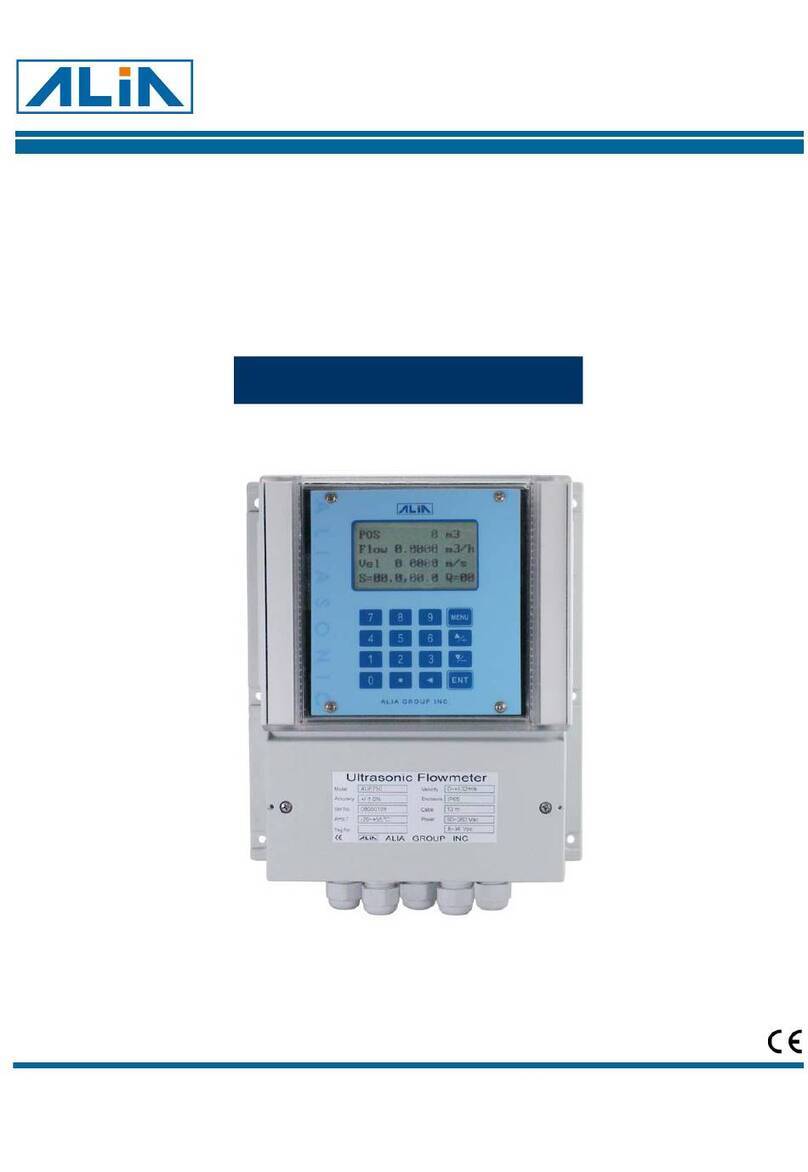
Alia AUF610 Series User manual

AUF610 Series Operation Manual OP610.1.1.5R1ENG
1
Portable Transit-Time Ultrasonic Flowmeter
Model AUF610 Series
Operation Manual
Alia Group Inc. URL : http://www.alia-inc.com
TEL : +1 - 302 - 213 - 0106 FAX : +1 - 302 - 213 - 0107 OP610.1.1.5.R1ENG
ALIASONI
C
®

AUF610 Series Operation Manual OP610.1.1.5R1ENG
2
Index
0 Table of Contents ---------------------------------------------------------2
1 Introduction -------------------------------------------------------------4
1.1 Preface-----------------------------------------------------------------4
1.2 Features - - - - - - - - - - - - - - - - - - - ---------------------------------------------4
1.3 Princi
p
leofMeasurement-----------------------------------------------------5
1.4 Product identification - - - - - - - - - - - - --------------------------------------------6
1.5 Parts Identification - - - - - - - - - - - - - ---------------------------------------------6
1.6 T
yp
ical A
pp
lications---------------------------------------------------------9
1.7 Data Inte
g
rit
y
and Built-in Time-Kee
p
e
r
-------------------------------------------10
1.8 S
p
ecifications-------------------------------------------------------------10
2 Makin
g
a Measurement -----------------------------------------------------11
2.1 Built-in Batter
y
------------------------------------------------------------11
2.2 Power U
p
Sel
f
-Check-------------------------------------------------------11
2.3 Ke
yp
ad-----------------------------------------------------------------11
2.4 Ke
y
Board Entr
y
- - - - - - - - - - - - - - - - - - - - - - - - - - - - - - - - - - - - - - - - - - - - - - - - - - - - - - - - - - - 12
2.5 Menu Item Or
g
anization------------------------------------------------------12
2.6 Menu Windows - - - - - - - - - - - - - - - ---------------------------------------------12
2.7 SET UP
(
Quick Start
)
--------------------------------------------------------13
2.8 Transducers Mountin
g
/Location-----------------------------------------------14
2.9 TransducersInstallation------------------------------------------------------15
2.9.1 Transducers S
p
acin
g
--------------------------------------------------------15
2.9.2 V-method Installation - - - - - - - - - - - - - - - - - - - - - - ----------------------------------16
2.9.3 Z-method Installation - - - - - - - - - - - - - - - - - - - - - - ----------------------------------16
2.9.4 W-method Installation - - - - - - - - - - ---------------------------------------------16
2.10 InstallationVerification-------------------------------------------------------17
2.10.1 Si
g
nal Stren
g
th------------------------------------------------------------17
2.10.2 Si
g
nal Qualit
y
-------------------------------------------------------------17
2.10.3 Total Transit Time and Delta Time - - ---------------------------------------------17
2.10.4 Time Ratio between the Measured Total Transit Time and the Calculated Time - - - - - - - - - - - - - - - 17
3 How to Use - - - - - - - - - - - - - - - - - - - - - - - - - - - - - - - - - - - - - - - - - - - - - - - - - - - - - - - - - - - - - - 18
3.1 How to determine if the instrument is workin
g
p
ro
p
erl
y
? - - - - - - - - - - - - - - - - - - - - - - - - - - - - - - - 18
3.2 How to
j
ud
g
e the li
q
uid flowin
g
direction?-----------------------------------------18
3.3 How to chan
g
e between units s
y
stems?------------------------------------------18
3.4 How to select a re
q
uiredflowrateunit?-------------------------------------------18
3.5 How to use the totalizer multi
p
lier?----------------------------------------------18
3.6 How to o
p
enorshutthetotalizers?----------------------------------------------18
3.7 Howtoresetthetotalizers?---------------------------------------------------18
3.8 How to restore factor
y
default settin
g
?--------------------------------------------18
3.9 How to use the dam
p
er?-----------------------------------------------------18
3.10 Howtousethezero-cutofffunction?---------------------------------------------19
3.11 How to setu
p
a zero
p
oint?----------------------------------------------------19

AUF610 Series Operation Manual OP610.1.1.5R1ENG
3
3.12 How to
g
etascalefactorforcalibration?------------------------------------------19
3.13 How to use the o
p
erationlocker?-----------------------------------------------19
3.14 How to use the built-in data lo
gg
er?---------------------------------------------19
3.15 How to use the Fre
q
uenc
y
Out
p
ut?----------------------------------------------19
3.16 How to use the Totalizer Pulse Out
p
ut?-------------------------------------------20
3.17 How to
p
roduce an alarm si
g
nal? - - - - - - - - - - - - - - - - - - - - - - - - - - - - - - - - - - - - - - - - - - - - - - - 20
3.18 Howtousethebuilt-inBuzzer?------------------------------------------------20
3.19 How to use the OCT out
p
ut?--------------------------------------------------20
3.20 How to modif
y
the built-in calendar? - - - ------------------------------------------20
3.21 How to ad
j
usttheLCDcontrast?------------------------------------------------21
3.22 How to use the R232 serial interface? - - - - - - - - - - - - - - - - - - - - - - - - - - - - - - - - - - - - - - - - - - - - 21
3.23 HowtoviewtheDateTotalizers?-----------------------------------------------21
3.24 How to use the Workin
g
Timer?------------------------------------------------21
3.25 How to use the manual totalizer? - - ---------------------------------------------21
3.26 How to check the ESN and other details? - - - - - ------------------------------------21
3.27 How to know how lon
g
the batter
y
will last? - - - - - - - - - - - - - - - - - - - - - - - - - - - - - - - - - - - - - - - - 21
3.28 How to char
g
e the built-in batter
y
?----------------------------------------------21
4 Menu Window Details
(
Table 2
)
----------------------------------------------22
5 Troubleshootin
g
----------------------------------------------------------26
5.1 Powe
r
-on Error Dis
p
la
y
s and Corrective Actions -------------------------------------26
5.2 O
p
erational E
r
ror Codes and Corrective Actions -------------------------------------26
5.3 Other Trouble Shootin
g
Ti
p
s---------------------------------------------------27
6 Communication Protocol & Remote O
p
eration -----------------------------------28
6.1 Interface Pin-out Definition - - - - - - - - - - - - - - - - - - - - - - - - - - - - - - - - - - - - - - - - - - - - - - - - - - - - 28
6.2 Communication Protocol Re
g
isters----------------------------------------------28
6.3 Protocol Prefix Usa
g
e-------------------------------------------------------28
6.4 Ke
yp
ad Codin
g
------------------------------------------------------------30
7 Warrant
y
and Service ------------------------------------------------------31
7.1 Warrant
y
----------------------------------------------------------------31
7.2 Service-----------------------------------------------------------------31
7.3 Software U
pg
rade Service - - - - - - - - --------------------------------------------31
7.4 Product identification - - - - - - - - - - - - - -------------------------------------------31
A
PPENDIXI------------------------------------------------------------------31
A
PPENDIXII------------------------------------------------------------------32
A
PPENDIX III - - - - - - - - - - - - - - - - - - - - ---------------------------------------------33
A
PPENDIXIV-----------------------------------------------------------------34
A
PPENDIXV----------------------------------------------------------------- 37

AUF610 Series Operation Manual OP610.1.1.5R1ENG
4
1. Introduction
1.1 Preface
Welcome to the Alia AUF610 (Version 8.xx) series ultrasonic flow meter. The AUF610 is manufactured
using patented technologies and is equipped with more functions and advanced performance than ever.
The latest Version 8.xx Series Ultrasonic Flow Meter is an upgrade of the Version 7.xx Series Ultrasonic
Flow Meter. The new Version 8.xx retains all the excellent features and functions in previous versions
including the sonic pulsed measurement technology, the ultrasonic triggering and signal receiving circuits’
ability to reliably process low input signals. The main improvements affect the battery supply circuit and the
transmitting circuits. These improvements have been integrated into this new version to allow us to deliver
a more advanced measurement technologies and reliable ultrasonic flow meter.
The AUF610 Series flow meter incorporates the latest ICs manufactured from the famous semiconductor
manufacturers like Philips and TI. The hardware is easy to use and features intuitive operation, high
accuracy and outstanding reliability. The system’s feature rich software provides a user friendly interface
that provides the operator with access to more information for accurately monitoring and analyzing pipe
flows. The AUF610 uses a patented balanced low voltage, multi-pulse, triggering circuit. This increases
signal to noise ratio within the signal processing unit resulting in a meter that performs superbly in
demanding industrial environments. Even in electrically noisy locations with VFD’s and high voltage in
close proximity the Alia AUF-610 provides superior performance.
Other outstanding features:
• The signal receiving circuits feature self-adapting performance so as to ensure that the user can easily
operate the instrument without any adjustment.
• The built-in rechargeable Ni-H battery can work continuously for more than 10 hours without recharge.
• User-friendly dual language software interface (English & Chinese)
1.2 Features
* Accuracy: +/- 1.0% of velocity and +/-2% value of reading (0.5 to 30m/s) NOTE (1)
* Repeatability: 0.2% of reading
* Dual Language Display (Chinese and English)
* 4 flow totalizers
* Patent balanced low-voltage multi-pulse measuring technology
* Built-in date totalizers
* Ultrasonic triggering
* Built-in data-logger
* High Signal to noise ensures signal integrity in electrically & acoustically noisy environments
* 0.5 second totalizing period
* 100 Pico-second resolution of time measurement

AUF610 Series Operation Manual OP610.1.1.5R1ENG
5
1.3 Principle of Measurement
The AUF610 ultrasonic flow meter is designed to measure the fluid velocity of clean homogeneous liquids
in a closed conduit. The transducers are the ‘outside the pipe’, non-contacting, clamp-on type. This
ensures non-fouling operation and a simple, easy installation.
The AUF610 transit time flow meter utilizes two ultra-sonic transducers. Each one is both a transmitter and
a receiver. The transducers are clamped on the outside of a closed pipe in a pre-determined distance from
each other. The pipe size, pipe material and process (liquid) characteristics dictate where and how far
apart the transducers are mounted. If sound crosses the pipe once it is called the Z-method. If the sound
transverses the pipe twice it is called the V-method. If the sound transverses the pipe four times then it is
known as the W-method. The flow meter operates by alternately transmitting and receiving frequency
modulated bursts of sound energy between the two transducers. Once upstream and once downstream
and then accurately determining the time difference between the two sonic beams and the time difference
is a linear, accurate and repeatable measurement of the process velocity within the pipe. Calculating the
pipe’s internal area and integrating the velocity measurement over time results in the flow rate.
(see.Figure)
v= MD*
SIN 2
△
T
×Tup Tdown*0
Figure
NOTES:
Ө= the angle to the flow direction
M = the transit time of the ultrasonic beam
D = the pipe diameter
Tup = the downstream transit time
Tdown = the upstream transit time
△ T = Tup -Tdown
Up stream transducer
Tup
Tdown
Down stream transducer
Spacing

AUF610 Series Operation Manual OP610.1.1.5R1ENG
6
1.4 Product identification
Each AUF610 Series flow meter has a unique product identification or ESN# written in the software and
can only be accessed by the manufacturer. In the case of an equipment failure, this number, located on
0menu window M61, MUST be provided when contacting the manufacturer.
1.5 Parts Identification
Top v iew
upstream transducer socke
t
downstream transducer socke
t
bottom view
RS-232 communication interface
Pins for battery recharge

AUF610 Series Operation Manual OP610.1.1.5R1ENG
7
AUF 610 HANDHELD
ULTRASONIC FLOWMETER
AUF610
POS +2 m3
Flow 0.0000 m3/h
Vel 0.0000 m/s
S=000,000 Q=00 1
Front view
LCD DISPLAY
LED Charging
Indicator
Keypad

AUF610 Series Operation Manual OP610.1.1.5R1ENG
8
Standard Type Temperature Sensor (15mm~6000mm)
High Temperature Type Sensor (15mm~1000mm)
Transducer Standard Cables : 5M
Blue Terminal
5m
Blue Terminal
Cable 5m*2
Red Terminal Red Terminal

AUF610 Series Operation Manual OP610.1.1.5R1ENG
9
Transducer Expansion Cables : 5M
HandHeld Power Supply Cable
HandHeld RS-232 Interface
1.6 Typical Applications
The AUF610 flow meter can be applied to a wide range of measurements. The measured pipe ranges
15~6000 mm [1/2’’~240’’]. The AUF610 will measure a broad range of clean homogeneous liquid
processes including ultra-pure liquids, potable water, chemicals, reclaimed water, cooling water, river water,
plant effluent, etc. The instrument transducers are mounted outside the pipe and are therefore not in
contact with the process and have no moving parts. The flow meter is not affected by system pressure,
fouling or wear as would an orifice plate. The High Temperature Type AUF610 transducers are rated to
160℃. Higher temperature ratings can be achieved by using special transducers. Please contact your Alia
representative for further details and assistance.
Blue Terminal
Red Terminal Red Terminal
Blue Terminal
5m
1m

AUF610 Series Operation Manual OP610.1.1.5R1ENG
10
1.7 Data Integrity and Built-in Time-Keeper
All user-configured values are retained in non-volatile flash memory that will retain its memory for over 100
years regardless of power status. Password protection is provided to avoid inadvertent configuration
changes or totalizer resets.
A time-keeper is integrated in the flow meter for the indexing of date totalizing. It also works as the time
base for the of flow totalizer. It keeps operating as long as the battery’s terminal voltage is over 1.5V. In
case of total battery failure, the time-keeper will not keep running and it will lose the correct time. The user
must re-enter the proper time in these instances. An improper actual time has no other affect but date
indexing.
1.8 Specifications
Linearity 0.5%
Repeatability 0.2% value of Reading
Accuracy ±1% (R) +/- 2% value of reading ( 0.5 to 30 m/sec)
Response Time 0-999 seconds, user-configurable
Velocity ±32m/s
Pipe Size 15mm-6000mm
Rate Units
Meter, Feet, Cubic Meter, Liter, Cubic Feet, USA Gallon,
Imperial Gallon, Oil Barrel, USA Liquid Barrel, Imperial Liquid
Barrel, Million USA Gallons. User configurable.
Totalizer 7-digit totals for net, positive and negative flow
Liquid Types Clean , homogeneous liquids
Security Setup values Modification Lockout. Access code needs
unlocking
Display 4*8 Chinese characters or 4*16 English letters
Communication
Interface
RS-232C, Baud-rate: from 75 to 57600. Manufacturer’s
protocol Same as FUJI ultrasonic flow meter. Driver data
available on demand, User protocols can be made on
enquiry.
Transducers Model M1 for standard, other 3 models for optional
Transducer Cord
Length
Standard 2*5 meters, optional 2*10 meters
Power Supply
3 AAA Ni-H built-in batteries. When fully recharged it will last
over 10 hours of operation.
100V~240VAC for the charger
Data Logger Built-in data logger can store over 2000 lines of data
Manual Totalizer 7-digit press-key-to-go totalizer for calibration
Housing Material ABS
Case Size 100*66*20MM
Handset Weight 514(1.2 Ibs) with batteries

AUF610 Series Operation Manual OP610.1.1.5R1ENG
11
2. Making a Measurement
2.1 Built-in Battery
The instrument can operate either from the built-in Ni-H rechargeable battery, which will last over 10 hours
of continuous operation when fully recharged, or from an external AC/power supply from the battery
charger. The battery charging circuitry utilizes both constant-current and constant-voltage. This allows fast
charging initially and then reverting to trickle charge when the battery nears the full recharge. Generally,
when the green LED starts to turn on, the battery is nearly 95% charged. When the red LED is off, the
battery will be 98% recharged.
Trickle charging ensures that over-recharging is never a concern. The charger can if fact remain
connected to the handset for tests or monitoring situations requiring more time than the standard battery
life.
A fully charged battery will show an internal battery terminal voltage of approximately 4.25V. The terminal
voltage and an approximate battery time remaining are displayed on window M07. Please note that the
estimator is not an exact indication of time remaining but only estimation. Use the Mains power supply for
long term testing. It is NOT advisable to run the system below a 3.0V level at the terminals.
2.2 Power Up Self-Check
Press the ON key to switch on the instrument and press the OFF to turn off the power. Once the flow
meter is switched on, it will run a self diagnostic program, checking first the hardware and then the
software integrity. If there are any issues, an error message will appear on the display. Table 3 in Section 5
on Troubleshooting will explain any errors and advise of corrective action.
Following the startup self-diagnostics, the flow meter will display Menu Window Number 01 (M01). This
windows displays the Process Velocity, the calculated Flow Rate, the Positive Totalizer (+), Signal Strength
and Signal Quality. All these values are based on the application parameters last configured in the AUF610
handheld.
The flow measurement program always operates in the background of the user interface.
2.3 Keypad
The keypad for the operation of the flow meter has 18 keys, as
shown by the diagram below. Keys 0 to 9 and the . key
are for entering numerical values.
The ▲/+ and ▼/- keys move the screen cursor up & down the
menu window. They also acts as the+/-keys when entering
numerical values. The key is for backspacing or when there
wants to move left or backspace the character that is located to
the left of the cursor. The ENT key is used to ENTER data or
inputting any selections.
The MENU key (referred to as the M key) allows direct access
to all the menu items listed later in this manual. Pressing the
MENU button followed by a two digit number will cause the user
to be immediately directed to that menu item. The ON key is for
power on. The OFF key is for power off.
123
456
789
0
ON OFF
MENU
CHARGE
ENT
ALI A GROUP I NC.

AUF610 Series Operation Manual OP610.1.1.5R1ENG
12
2.4 Key Board Entry
The flow measurement (and totalizers) will continue to run no matter what user menu window is being
browsed or viewed. The flow measurement will only change when the user enters new application
parameters. Whenever a modification to the flow metering system is made that affects the sound path the
meter will automatically determine the threshold of transmitted signal and adjust the gain on the receiving
signal amplifiers. An internal counter monitors the progress of this operation. The progress is shown on the
right lower corner of the LCD display. Examples are new pipe parameters, the power is switched on or the
transducers have been adjusted on the pipe. All user entered configuration values are retained in
NVRAM of the flow meter, until modified by the user. Frequently used configurations can be stored in one
of up to 18 memory locations for rapid recall and setup. (Use menu location M27)
2.5 Menu Item Organization
M00~M09 items display REAL_TIME DATA including: flow rate, process velocity, date/ time, totalizers, battery
voltage and estimated working hours for the battery.
M10~M29 items relate to entering pipe parameters.
M30~M38 items permit flow rate unit and totalizer unit set up.
M40~M49 items allow adjust the meter for process dynamics including response time, zeroing, calibration and
modification password setup.
M50~M53 items are for the built-in logger.
M60~M78 items are for time-keeper initialization, version and ESN information viewing and alarms.
M82 is for viewing date totalizer.
M90~M94 items are diagnostic values used to optimize or confirm the meter’s operation.
M97~M99 are commands used to force the output of internal data.
M+0~M+8 are windows for some additional functions, including a scientific calculator, viewer on records such as
total working hours, turn-on and turn-off times, dates and times when the flow meter has been turned off.
There are three types of menu windows:
(1) Numerical entry windows (i.e. M11 for the entering of pipe OD)
(2) An entry window for selecting options. (i.e.M14 for the selection of pipe materials)
(3) Display windows (i.e. M01 displays process conditions)
2.6 Menu Windows
The user interface of this flow meter comprises about 100 different menu windows that are numbered by
M00, M01, M02…M99.
There are 2 methods to enter menu windows:
(1) Directly going/entering. The user can press the MENU key plus two-digit number
Keys. For example, the menu window M11 is for the entering of pipe outer diameter. The display will go
to the M11 menu window after the user presses MENU 1 1 , then press the ENT key and
enter a value. Pressing the ENT key again will enter the value.
(2) Pressing ▲/+ and ▼/- keys. Each time the ▼/- key is pressed the menus will advance to the next
item in order. For example, if the current window is on M12, the display will go to the number M13
window after pressing the ▼/- key.

AUF610 Series Operation Manual OP610.1.1.5R1ENG
13
2.7 SET UP (Quick Start)
To begin, select the system of measurement (US or Metric) in MENU Item 30.
The user must supply any two of the following four items of pipe information. The meter will calculate the
rest. (There are tables in the appendices at the end of this manual for reference)
• Pipe circumference (M10)
• Pipe OD (M11)
• Pipe wall thickness (M12)
• Pipe ID (M13)
Enter the following pipe data and process data in the appropriate Menu locations:
• Pipe Material (M14)
• Lined Pipe (M16)
• Process Liquid (M20)
• Transducer type (M23)
* For Alia select either #11 (Standard-TS) or #12 (Standard-TM)
• Transducer Mounting Configuration (M24)
The selections on M23 & M24 are is pipe size dependent. The diagrams on pages 9, 17 & 18 will guide the
user.
Handheld Menu Item 25 describes the transducer spacing that the Handheld has calculated as
required for your application. It is always a good idea to scroll back through the menu items to
confirm that the correct data was entered as the spacing / distance between the transducers is
based on this information and is critical. See Section 2.8 for correct transducer installation
Now proceed to configure the units of measurement (flow rate) and the totalizer units. This is done as
follows:
• Flow Rate / Time Units (M31)
• Totalizer Units (M32)
• Totalizer Multiplier (M33)
• Turn OFF or ON Totalizers (M34,35,36)
Positive, Negative, Net Totalizers
• Totalizer reset (see Item M37 page 22)
Now, if the transducers are installed correctly and the above is done,the meter is ready to measure.
Press M01. At the bottom of the window the S value and the Q value should be in the 700,000 to 800,000
and >60% respectively. This may take a few seconds as the meter adjusts its gain for the new installation.
Finally, determine if any signal is being generated at zero flow. This will show up as flow rate or flow
velocity when there is NO FLOW. This can occur in environmentally noisy locations with pipe vibration. If
there is a flow reading when there is no flow then the meter must be zeroed. Go to M42, Press ENTER
then follow the on-screen instructions. (There is a counter to monitor progress) ENSURE THERE IS NO
FLOW.
You should now be making an accurate measurement. If this is a common measurement it might be
advantageous to SAVE it to a memory location (M26) for future use. Cont’ next page…
Cont’… The following will facilitate the operation of this instrument:
(1) When the window display is between M00 and M09 it is only necessary to press a single digit
number key to access other windows between M00 & M09.
(2) When the window display is between M00 and M09 it is only necessary to press a single digit
number key to access other windows between M00 & M09.
(3) When the window display is between M00 and M09, repeated pressing the ENT key will cycle
between M00 and M90.
(4) When the window display is M25, press ENT key to go to M01.

AUF610 Series Operation Manual OP610.1.1.5R1ENG
14
2.8 Transducers Mounting / Location
The first step in the installation process is the selection of an optimum location in order to obtain better
signal quality, which ensures a more reliable and more accurate measurement. For this to be completed
effectively, it is best to have a basic knowledge of the hydraulic system about to be measured.
The optimum location will be length of straight pipe that is always full of process and has no bubbles. The
piping can be in vertical (flow going up) or horizontal position but should have the following recommended
straight lengths of pipe both upstream and downstream as defined in diameters.
TABLE 1
Piping Configuration and Transducer
Position
Upstream
Dimension
L up x Diameters
Downstream
Dimension
L dn X Diameters
10D 5D
10D 5D
10D 5D
12D 5D
20D 5D
20D 5D
30D 5D
L up L dn
L up L dn
L up L dn
L up L dn
L up L d n
L u p L d n
L up L dn

AUF610 Series Operation Manual OP610.1.1.5R1ENG
15
Examples of optimum locations:
Guidelines for selection of optimum mounting locations:
(1) Install the transducers on a longer length of the straight pipe.
(2) Make sure that the temperature at the selected location does not exceed the range of the
transducers. Generally speaking, the closer to the room temperature, the better.
(3) Consider the possibility that the pipe has coated over time.
(4) Select a straight length of a relatively newer pipe. If the conditions are not optimum, consider the
coating as part of the liner for a better result.
(5) Some pipes are dual walled with a plastic line or with air in between. The system may not work in the
latter case. Also the thickness between the outer pipe and the liner may vary. This can prevent or disrupt
ultrasonic wave propagation. Avoid this kind of pipe. Alternately, consider permanently installed through
the pipe, hot tap type transducers as available from Alia.
2.9 Transducers Installation
The transducers used by the AUF610 series ultrasonic flow meter are made of piezoelectric crystals both
for transmitting and receiving ultrasonic signals. Measuring the traveling time difference of the upstream
verses downstream ultrasonic signals travelling in the pipe makes the measurement. Since the measured
time difference is very small, the spacing, alignment and acoustic coupling of the transducers are factors
critical for the specified measurement performance of the system. Great care should be taken when
installing the transducers.
Here are some guidelines:
• Locate an optimum position where the straight pipe length is sufficient, and where pipes are in a
favorable condition, e.g., newer pipes with no rust and ease of operation.
• Clean any dust and rust. For a better result, polishing the pipe with a sander is recommended.
• Apply adequate coupling grease to the spot where the transducers are to be installed and leave no
gap between the pipe surface and the transducers.
• Extra care should be taken to avoid any sand or dust particles left between the pipe outer surface
and the transducers.
• To avoid gas bubbles inside the upper part of the pipe, the transducers should be installed on the
side of the pipe at the 2:00/10:00, 3:00/9:00 or 4:00/8:00 o’clock positions.
2.9.1 Transducers Spacing
The spacing value shown on menu window M25 refers to the distance of inner spacing between the
transducers. It is calculated based on the preliminary pipe data, sonic path info (see 2.9.2 below) and
process information entered by the user in the previous menu items. If the spacing does not sound right
(i.e. spacing of 2” on a 10” pipe then checks the setup figures. Data can get entered incorrectly especially
with inexperienced users. The spacing is important,and should be measured from the indicator which is an
integral part of each transducer assembly.
As important as the Transducer spacing is the ‘bounce pattern’ of the Ultra sonic signal. This is described
below.

AUF610 Series Operation Manual OP610.1.1.5R1ENG
16
2.9.2 V-method Installation
V-method installation is the most commonly used mode. It is used most frequently on pipes with ID’s
ranging from 15 millimeter to 400 millimeter. It is also called reflective mode or single bounce method.
2.9.3 Z-method Installation
Z-method is commonly used when the pipe diameter is between200millimeters and 6000 millimeters.
2.9.4 W-method Installation (not used as often but has its’ applications)
W-method is usually used on plastic pipes with a diameter from 15 millimeters to 50 millimeters
TOP VIEW OF PIPE
sensors spacing
TOP VIEW OF PIPE
sensors spacing
TOP VIEW OF PIPE
sensors spacing

AUF610 Series Operation Manual OP610.1.1.5R1ENG
17
2.10 Installation Verification
During the process of the installation, one can: check the receiving signal strength, the signal quality Q
value, the transit time differential of the signals, the estimated speed of sound in the process, the
measured traveling time of the signals and the calculated traveling time ratio. Therefore, optimum
measurement results and successful results can be achieved.
2.10.1 Signal Strength
Signal strength indicates the amplitude of the received ultrasonic signals in the form of an arbitrary 3-digit
number. “000” is no signal detected and 999 indicates that the maximum signal strength available has
been received.
The instrument will provide a reliable measurement if the signal strength ranges from 500 to 999, however
the stronger the signal the better. The instrument continually updates the flow reading by time averaging
the received velocity signal. Therefore a stronger signal ensures fewer situations a signal path is
compromised possibly affecting the overall flow rate and total. The following methods help optimize
signals:
(1) Relocate a more favorable location, if the current location is not good enough for a stable and
reliable flow reading, or if the signal strength is lower than 700.
(2) Try to polish the outer surface of the pipe, and apply more ‘grease’ coupler to increase the signal
strength.
(3) Adjust the transducers both vertically and horizontally while checking the varying signal strength,
stop at the highest position, and then check the transducers spacing to make sure the transducers spacing
is the same as what the M25 shows.
2.10.2 Signal Quality
Signal quality is indicated on the lower right-hand side of the display and denoted as ‘Q’. The higher a Q
value the better the guarantee of a reliable measurement. Under normal pipe condition, the Q value is in
the range 60-90%. Causes for a lower Q value could be:
(1) Interference of other instruments and devices such as high powered electrical equipment working
nearby. Relocate the flow meter to a new place where the interference will be reduced.
(2) Bad sonic coupling for the transducers with the pipe. Try to apply more coupler or clean the surface, etc
(3 )Pipe location is bad. Relocation is recommended.
2.10.3 Total Transit Time and Delta Time
The numbers displayed on menu window M93 are called total transit time and delta time respectively. They
are the raw data the instrument uses to calculate the flow velocity inside the pipe. The flow velocity / rate
indication is a function of the total time and delta time. The total transit time should remain stable or vary
little. If the delta time fluctuates higher than 20%, it means there are probably issues with the transducer
installation.
2.10.4 Time Ratio between the Measured Total Transit Time and the Calculated Time
This ratio would be used to check the transducer installation. If the pipe parameters are entered correctly
and the transducers are installed properly, the value for this ratio should be in the range of 100±3. If this
range is exceeded, it should be checked:
(1) If the pipe parameters are correctly entered.
(2) If the actual spacing of the transducers is right and the same as what the window M25 shows.
(3) If the transducers are installed properly in the right directions.
(4) If the mounting location is good and if the pipe has changed shape or if there is too much fouling
inside the pipes.
(5) Other issues or conditions not conducive to Ultra sonic measurement..

AUF610 Series Operation Manual OP610.1.1.5R1ENG
18
3. How to Use
3.1 How to determine if the instrument is working properly?
When ‘R’ is displayed in the lowest right corner of LCD display, the instrument is working properly,
generally speaking.
If an ‘H’ flashes on than place, there could be poor signal received. Please refer to the chapters on
diagnosis.
If an ‘I’ is displayed, it means that there is no signal detected.
If a ‘J’ is displayed, it means that the hardware of this instrument could be out of order. Refer to the chapter
on diagnosis.
3.2 How to judge the liquid flowing direction?
(1) Make sure that the instrument works properly
(2) Check the flow rate for the indication. If the displayed value is POSITIVE, the direction of the flow will
be from the RED transducers to the BLUE transducers; if the displayed value is NEGATIVE, the direction
will be from the BLUE transducers to the RED transducers;
3.3 How to change between units systems?
Use menu window M30 for the selection of unit system in English or Metric system.
3.4 How to select a required flow rate unit?
Use menu window M31 to select the flow unit first and then the base time unit.
3.5 How to use the totalizer multiplier?
Use window M33 to select a proper totalizer. Make sure that the totalizer pulse rate is appropriate for the
application, the receiving instrument yet still output the resolution necessary to properly characterize the
flow.
If the totalizer multiplier is too small, there can be a loss of accumulation pulse because the output device
can output only one pulse in a measurement period (500milliseconds)
If the totalizer multiplier is too large, the output pulse will be too fewer for the devices that are connected
with the instrument for a quicker response.
3.6 How to open or shut the totalizers?
Use M34, M35 and M36 to turn on or turn off the POS, NEG, or NET totalizer respectively.
3.7 How to reset the totalizers?
Use M37 to reset each respective totalizer.
3.8 How to restore factory default setting?
Use M37, when the ‘selection’ message is displayed. Press the dot key first and the message ‘Master
Erase’ will display, then press the backspace key. The master erase step will erase all the
parameters entered by the user and setup the instrument with default values.
3.9 How to use the damper?
The damper acts as a filter for a stable reading. If ‘0’ is entered in window M40 that means there is no
damping. A larger number slows down the instrument’s response causing it to appear more stable.
However remember that a larger setting will prevent a quick response in a dynamic situation..
Numbers 0 to 10 are commonly used for the damper value.

AUF610 Series Operation Manual OP610.1.1.5R1ENG
19
3.10 How to use the zero-cutoff function?
The number displayed in window M41 is called the low-flow cutoff value. The flow meter will replace these
any flow rate below this value with zero. This is used in situation where hydraulic or ambient noise is
causing a flow reading in a pipe where there is no flow. This ensures that the flow meter will not totalize
false value.
3.11 How to setup a zero point?
There exists a ‘Zero Point’ with certain installation which means the flow meter will display a non-zero
value when the flow is absolutely stopped. In this case, setting a zero point with the function in window
M42 will bring a more accurate measurement result.
Make sure that the flow is absolutely stopped, then run the function in window M42 by pressing the ENT
key.
3.12 How to get a scale factor for calibration?
A scale factor is the ratio between the ‘actual flow rate’ and the indicated value by the flow meter.
Knowledgeable plant personnel should only use this as properly set up the meter is accurate.
The scale factor can be determined by calibration with flow calibration equipment.
3.13 How to use the operation locker?
The system locker provides a means of preventing inadvertent configuration changes or totalizer resets.
When the system is locked, menu window browsing can be done without affecting any change, but any
modifications are prohibited.
The system can be locked without a password or with a one 1 to 4 digit password. With a no-password
locking, directly press the ENT key when the password input prompt displays. If the password is forgotten,
please contact the factory.
3.14 How to use the built-in data logger?
The data logger has a space of 24K bytes of memory, which will hold about 2000 lines of data.
Use M50 to turn on the logger and for the selection for the items that is going to be logged.
Use M51 for the times when the logging begins and at how long an interval sustains and how long the data
logging will last.
Use M52 for the direction of logging data. The default setting will permit the logging data to be stored in the
logger buffer.
Logging data can be redirected to the RS-232C interface without being stored into the logger buffer.
Use M53 to view the data in the logger buffer.
Dumping the logging data through the RS-232C interface and the clearing of the buffer can be operated
with a function in window M52.
3.15 How to use the Frequency Output?
There is a Frequency Output in all AUF610 series flow meters. This frequency output signal, which
represents the flow rate, is intended to connect with other instruments.
The Frequency Output is totally user-configurable. Generally, four parameters should be configured for the
setups.
Enter the lower flow rate value in window M68 and the higher flow rate value in window M69.
Enter the frequency range in window M67.
For example, assume that the flow rate varies in a range 0m3/h to 3000m3/h, and an output signal is at a
maximum frequency of 200Hz is going to be required for other instrumentation. The user should enter 0 in
M68 AND 3000IN M69, and enter 200 and 1000 in window M67.
Please note that the user has to make the selection with OCT setups in window M78 by selecting the 13
option reading like ‘FO output’ to direct the frequency output to the OCT OUTPUT hardware device.

AUF610 Series Operation Manual OP610.1.1.5R1ENG
20
3.16 How to use the Totalizer Pulse Output?
The totalizer output will produce a pulse output with every unit flow of the totalizer .
Refer 3.4 and 3.5 for the setups of the totalizer units and multiplier.
The totalizer pulse output can only be realized by mapping the pulse output to the OCT or BUZZER
hardware devices.
For example, assume that the POS totalizer pulse output is needed, and every pulse should represent 0.1
cubic meter of liquid flow; the pulse output will be mapped to the internal Buzzer, so that with every 0.1
cubic meter of flow the BUZZER will beep for a while.
The following setups should be taken/performed:
(1) Select the unit Cubic Meter under window M32.
(2) Select the Multiplier as ‘2. x0.1’ under window M33.
(3) Select the output option ‘9. POS INT Pulse’ under window M77. (INT stands for totalized)
3.17 How to produce an alarm signal?
There are 2 types of hardware alarm signals that are available with this instrument. One is the Buzzer, and
the other is the OCT output.
Both for the BUZZER and OCT output the triggering sources of the event include the following:
(1) Alarms on when there is no receiving signal
(2) Alarms on when there is poor signal received.
(3) Alarms on when the flow meter is not in normal measurement modes.
(4) Alarms on reverse flow.
(5) Alarms on the overflow of the Frequency Output.
(6) Alarms on when the flow is out of a designated range set by the user.
There are two out-of-normal-range alarms in this instrument. They are called#1 Alarm and #2 Alarm. The
flow range can be user-configurable through M73, M74, M75 and M76.
For example, assume that the Buzzer should start beeping when the flow rate is less than 300m3/h and
greater than 2000m3/h, the following steps for setups would be recommended.
(1) Enter 300 under M73 for #1 alarm low flow rate.
(2) Enter 2000 under M74 for #1 alarm high flow rate.
(3) Select the item reading like ‘6. Alarm #1’ under M77.
3.18 How to use the built-in Buzzer?
The built-in buzzer is user-configurable. It can be used as an alarm. Use M77 for setups.
3.19 How to use the OCT output?
The OCT output is user-configurable, which can be performed by selecting the proper input source such as
pulse output. Use M78 for the setups.
Please make sure that the Frequency Output shares the OCT.
The OCT output shares pins with the RS-232C interface, and the terminal is at Pin 6 and the ground is at
Pin 5.
Max. Outer pressure V: 24VDC
Red Black
AUF610
6789
54321
Table of contents
Other Alia Measuring Instrument manuals