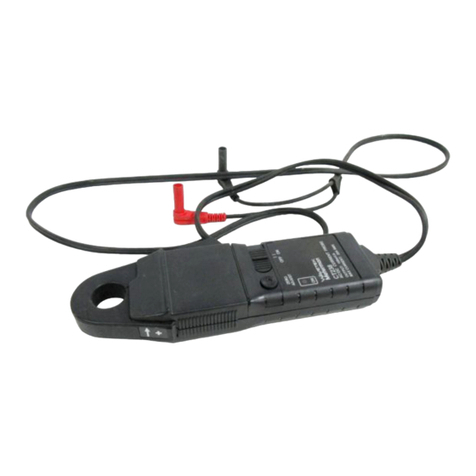
Wavetek 1034A Operating instructions

OPERATING AND MAINTENANCE
MANUAL
PORTABLE
RF POWER METER
MODEL 1034A
SERIAL NUMBER _
Copyright 1976 by Wavetek Microwave, Inc.
Printed in the United States
of
America. The information
comaine£l in
this
manual is intended for the operation and
maintenance
of
Wavetek Microwave equipment, and
is
not to be used othervtise
or
reproduced wilhout lhe wriuen
consent
of
Wavetek Microwave, Inc.
WAVETEK MICROWAVE, INC.
488 TASMAN DRIVE, SUNNYVALE, CALIFORNIA 94089
1499-14166
TEL: (408) 734-5780 TWX: (910) 339-9273 TELEX: 371-6460 Code
13
(2-88)
From the library of WØMTU

'\4odeJ
l034A
WARRANTY
Wavetek warrants that all products manufactured by Wavetek conform to published
Wavelek specifications
and
are Iree from defects in materials and workmanship for a period
of
one (1) year from the date of delivery when used under normal operating conditions
and within the service conditions for which they were furnished.
The obligation of Wavetek arising from a Warranty claim shall
be
limited to repairing, or
at
its option, replacing without charge. any product which
in
Wavetek's sale opinion proves
to be defective within the scope of the Warranty. In the event Wavetek is not able to modify,
repair or replace non-eonlorming defective parts
or
components to a condition
as
warrantied within a reasonable time after receipt thereof. Buyers shall
be
credited for their
value
at
the original purchase price.
Wavetek must be notified in writing of the
defect
or nonconformity within the Warranty
period and the affected product returned to Wavetek's factory or
to
an authorized service
center within (30) days after discovery of such defect or nonconformity.
For product warranties requiring return to Wavetek, products must be returned to a service
facility designated by Wavetek. Buyer shall prepay shipping charges, taxes, duties and
insurance for products returned to Wavetek for warranty service. Except for products
returned to Buyer from another country, Wavetek shall pay for return of products to Buyer.
Wavetek shall have
no
responsibility hereunder for any defect or damage caused
by
improper storage, improper installation, unauthorized modification, misuse, neglect,
inadequate maintenance, accident or for any product which has been repaired or altered
by anyone other than Wavetek or its authorized representative and not in accordance with
instructions furnished by Wavetek.
Exclusion
of
Other Warranties
The
Warranty
described
above is Buyer's
sale
and
exclusive
remedy
and
no
other
warranty,
whether
written
or
oral,
is
expressed
01'
implied.
Wavetek
specifically
disclaims
the
implied
warranties
of
merchantability
and
fitness
for
a
particular
pur-
pose.
No
statement, representation, agreement,
or
understanding, oral or written, made
by an agent, distributor, representative, or employee of Wavetel<, which
is
not contained
in the foregoing Warranty will
be
binding upon Wavetek, unless made
in
writing and
execuled by
an
authorized Wavetek employee.
Under
no
circumstances
shall
Wavetek
be
liable
for
any
direct,
indirect,
special,
incidental,
or
consequential
damages,
expenses,
losses
or
delays
(including
loss
of
profits)
based on
contract,
tort,
or
any
other
legal
theory.
From the library of WØMTU

Model
l034A
TABLE
OF
CONTENTS
Page
No.
Section
1 GENERAL INFORMATION
1.1
Wavetek
Microwave,
Inc.
(WMI)
Model
l034A
Portable
RF
Power
Meter
.......••.•........
1-1
1.2
Performance
Specifications
•...........•.••....••..•...••
1-2
Technical
Information
Sheet:
"Detectors
for
use
with
WMI
Scalar
Analyzers
and
Power
Meters"
Technical
Information
Sheet:
"Detector
Element
and
Tracking
Resistor
Replacement
Procedures"
Section
2 INITIAL INSTRUCTIONS
2.1
Receiving
Instructions
.•••••..••••.•••••••••••••..••••..
2-1
2.2
Returning
the
Instrument
..•.•..........•••••••••...•...•
2-1
2.3
Power
Requirements
.....•...........••........•••......
2-1
2.4
Chassis
Grounding
•••.•.........••••.........•••........
2-1
2.5
Detector
Handling
...•.•..•....•...........••..•.•••••.•
2-1
2.6
Accessories
..•.•••.•..•••.•...•.....•.•.••...•...•••••
2-2
Section
4 OPERATION
3.1
Front
Panel
Controls
.•.••.•.••..•...........•.........•
3-4
3.1.1
Power
Switch
..•.•..•....••........•••..••.••.•••
3-4
3.1.2
Meter
Range
Push
Buttons
.....••••.....••...•••..•
3-4
3.1.3
Zero
Button
&.
Screwdriver
Adjustment
............•.
3-4
3.1.4
Cal
Button
&:
Screwdriver
Adjustment
..........••...
3-4
3.1.5
Calibration
Factor
Control
{dB)
•........•..•.•...•.
3-4
3.1.6
Direct
50 /75
Adapter
Switch
•..•..••••..•....•.
3-4
3.2
Internal
Control,
Line
Voltage
Switch
.•......•.•....•...••
3-5
3.3
Front
Panel
Meter
•....•...•.......••........•..•.....•.
3-5
3.4
Front
Panel
Connectors
....•..•.........•.•.••
,
•..•••.••
3-5
3.4.1
Power
Input
........•........•........•..•.......
3-5
3.4.2
Output
BNC
Connector
....•..•.•..••••...........
3-5
3.4.3
Cal
Output
lOmW,
Type
N
Connector
..•....•.......
3-5
ii
From the library of WØMTU

Section
4
Section
5
Section
(,
Model
1034A
TABLE
OF
CONTENTS
(can't.)
3.5
Operating
Procedure
...•..•.....•••••...•.•.••..•.....•.
3-5
3.5.1 Use
of
the
Analog
Output
.•.•••...................
3-6
ELECTRICAL
DESCRIPTION
4.1
Introduction
............•...........•..................
4-4
4.2
Block
Diagram
Description
.......•......................
4-4
4.2.1
RF
Detector
.....•....•...•...•..................
4-4-
4.2.2
Thermistor
Bridge
Amplifier
................•......
4-4
4.2.3
Preamplifier
.................•............•......
4-4
4.2.4
Compensation
Circuit
..................•..........
4-4
it.2.5
Logarithmic
Amplifier
.................•.......•..
4-4-
4.2.6
Full-Scale
Range
Changing
4-5
4.3
Individual
Circuit
Block
Descriptions
...............•......
4-5
4.3.1
Input
Amplifier
...............•..................
4-5
4.3.2
Log
Conversion
Circuit
................•.......•..
4-5
4.3.3
Square-Law
Compensating
Circuit
.......•...•......
4-6
4.3.4
Temperature
Compensation
.............•...•...•..
4-6
4.3.5
Range
Switching
......................•..........
4-6
4.3.6
Calibrator
Oscillator
..................•..........
4-7
4.3.7
Power
Supply
.............................•......
4-7
PERFORMANCE
VERIFICA
nON
TESTS
5.1
General
............................................•.•
5-1
5.2
Equipment
Required
................•...•.•.....•.•.....
5-1
5.3
Tracking
With
DC
Voltage
................•.....•••••....
5-2
5.4
Calibrator
Output
Level
Check
............••.••..•.......
5-3
MAINTENANCE
6.1
Periodic
Maintenance
.......................•...•.......
6-1
6.2
Internal
Adjustments
and
Test
Points
.........•...•.......
6-1
6.2.1
Description
of
Adjustments
6-1
6.2.2
Description
of
Test
Points
.................•...•...
6-2
iii
From the library of WØMTU

Section
7
Section
8
Section
9
Table
4-A
Table
5-A
Figure
1-1
Figure
3-1
Figure
4-1
Figure
5-1
Figure
5-2
Figure
6-1
Model
l034A
TABLE
OF
CONTENTS
(con't.)
Page
No.
6.3 Calibration
6.3.1
Equipment
Required
....•.........•....•..........
6-2
6.3.2
Calibration
Procedure
..•...........•.•...........
6-3
6.4
Troubleshooting
.......•........••••..••.••••...•.......
6-6
6.5
Semiconductor
Devices
..........•..........•...........
6-7
6.6
Access
to
Internal
Components
•............•.............
6-7
SCHEMATIC DIAGRAMS
Table
of
Contents
for
Schematic
Diagrams
....•....•...........
7-1
REPLACEABLE
PARTS
LISTINGS
Table
of
Contents
for
Replaceable
Parts
Listings
............•...
8-1
MANUAL
CORRECTIONS
..............•........
follows
page
8-16
LIST
OF
ILLUSTRATIONS
(Tables
and
Figures)
Range
Switching
Gains
and
Offsets
....•.......................
4-7
Tracking
Performance
Tests
...................•..............
5-1
Model 1034A
Detector
Measurement
Accuracy
Model 1034A
Front
Panel.
.....................•..............
3-3
Model
l034A
Block
Diagram
.....•............................
4-3
Modified
Thermal
Converter
for
Checking
the
Calibrator
Output
........•................•.•
5-2
Fixture
for
Applying
DC
Voltage
to
the
Model
l034A
...•.....•..•
5-2
Chopper
Circuit
Timing
Diagram
......•........•.•...........•
6-7
iv
1-2
From the library of WØMTU

TEK
M I C
ROW
A V
E,
INCORPORATED
488
TASMAN
DRIVE,
SUNNYVALE,
CALIFORNIA
94089
Tel: (408)
734-5780
TWX:
(910)
339-9273
TECHNICAL
INFORMATION
DETECTORS
FOR
USE WITH WAVETEK MICROWAVE, INC. (WMI) SCALAR ANALYZERS
AND MODEL 1045 AND 1034A
POWER
METERS
The
purpose
of
this Technical
Information
sheet
is
to
define
parameters
and
specifications perti-
nent
to
all
of
the
detachable
detector
options
available
for
the
various
WMI
scalar
analyzer
systems
and
the
Model 1045
and
1034A
power
meters.
Parameters
common
to
each
of
the
detector
configurations
are
defined
first,
and
then
individual
detector
specifications
are
given.
WMI
offers
three
different
types
of
detectors
for
the
above
scalar
systems
and
power
meters.
These
include
the
single
diode
and
balanced
(dual diode) coaxial
detectors,
and
the
balanced
element
waveguide
detector.
The
single
diode
and
balanced
coaxial
detectors
ha
vea
maximum
power
rating
of
200m
W
(+
23dBm),
and
cover
the
frequency
range
of
IMHz
to
18.5GHz
or
IMHz
to
26.5GHz.
One
version
of
the
single
diode
detector
(used
with
the
Model
1045
Power
Meter)
has
a
built-in
atlenuator
to
allow it
to
measure
maxi-
mum
power
levels
up
to
lOW (+40dBm) CW
or
up
to
200W (+53dBm)
peak.
The
balanced
element
waveguide
detector
has
a
maximum
power
rating
of
loomW
(+dBm),
and
is
designed
for
the
frequency
range
from
26.5GHz
to
4O.0GHz.
Coaxial
detectors
are
available
with
type
N,
APC7,
and
APC3.5
(compatible
with
SMA)
connectors,
and
the
waveguide
detector
comes
with
a WR28
waveguide
(UG-599/U
Flange).
Frequencies
down to 100kHz
are
available
on
special
order,
and
various
types
of
50
to
75
ohm
adapters
are
available
for
the
coaxial
detectors.
HOTH:
If
it
is
desired
to
check
the
detector/
instrument
system
performance,
refer
to
the
Performance
Verification
Test
in
the
Operat-
ing and
Maintenance
Manual for
the
particu-
lar
instrument.
SINGLE DIODE DETECTOR FEATURES
AND SPECIFICA
nONS
Further
features
and
specifications
for
the
WMI
single
diode
detector
include
the
following:
o 70dB
Dynamic
Range
o
Temperature
Compensated
o
Linearity
Compensated
o
Frequency
Response
Curve
Da
ta
Accuracy:
The
uncertainty
of
cali-
bration
for
the
single diode
<Ietector
at
ImW (OdBm)
is
3%
to 18GHz and
5%
to
26.5GHz
o
Flatness:
The maximum
total
varia-
tion
of
flatness
for the single diode
detector
WIll
be
between
IdB and
4dB
from I
MHz
to 26.5GHz,
depend-
ing
on
the
detector
model and in-
strument
with which
it
is
used. (See
the
reverse
side
of
this
sheet.)
o
Return
Loss:
Return
loss
of
the
single diode
detector
is 25dB from
(MHz
to
2GHz
and
20dB from 2GHz
to 12.4GHz with any
connector.
With type N
or
APC7
connectors,
return
loss is 18dB from 12.4
to
18GHz and 14dB
between
18
and
18.5GHz. When
detectors
with
APC3.5
connectors
are
used,
return
loss is 16dB from 12.4
to
18GHz and
14dB
to
26.5GHz.
o Measurement Accuracy: Figures 6
and 7 show
the
measurement
accura-
cy for the single diode
detectors
used with
the
power
meters.
Single
dIode
detectors
specified for
the
1038-H/V
system
have a
measure-
ment
accuracy
of
O.ldB/lOdB plus
O.5dB
at
-50dBm
Figure
1.
Typico.l
Configurations
of
Wavetek
Microwaves
Single
Diode Detectors
BALANCED (DUAL DIODE) DETECTOR
FEATURES AND SPECIFICA
nONS
Further
features
and
specifications
for
the
WMI
balanced
detector
include
the
following:
o 76dB Dynamic Range
o
Effects
of
even
harmonics
are
re-
duced,
thereby
increasing
measure-
ment
accuracy
o Absorbs low level dc
offset
voltages
o Very low
thermal
drift
o
Temperature
Compensated
o
Linearity
Compensated
o Input
Impedance:
50 ohms, nominal
o
Frequency
Response
Curve
Data
Accuracy:
The
uncertainty
of
cali-
bration
for
the
balanced
detector
is
3%
to
18GHz and 5%
to
26.5GHz
o
Flatness:
The maximum
total
varia-
tion
of
flatness
for
the
balanced
detector
is 1.5dB from IMHz to
18GHz and 2dB from
18
to 26.5GHz
o
Return
Loss:
Return
loss
of
the
balanced
detector
is 20dB from
IMHz to 2GHz, 18dB
to
12.4GHz,
16dB to 18GHz, and
JOdB
up
to
26.5GHz.
o
Measurement
Accuracy:
See
Figure
4
Figure
2.
Wavetek
Microwave's
Patented
&lanced
(Dual Diode) Detector
DETECTOR HANDLING PRECAUTIONS
Any RF
detector
is,
of
necessity,
a
very
delicate
instrument
and
must
always
be handled
with
care.
Care
must
be
taken
to
avoid
el<ceedlng
the
detector's
electrical
rating
through
static
electricity,
power
input
greater
than
specified,
or use
of
measuring
equipment.
Also avoid
mechanical
stress
that
could
be
caused
by dropping
or
over-torquing
the
detector.
See
the
Operating
and
Maintenance
Manual
for
the
appropriate
instrument
with
which
the
detector
is
to
be used for
further
details.
(OVER)
1499-16428/2-88/500
From the library of WØMTU

'""'.,...WI'_
•
...,;~
Absolute
Maximum Diode
Part
Frequency
Power
Input
Without
Replacement
Number
Range
Damage
(Peak
or
CW)
Connector
Type
Kit No's.
NIO/NS20
System
Detectors
15176
lMHz
to
18.5GHz
200mW Type N
Balanced
15360
15177
IMHz
to
18.5GHz 200mW
APCl
Balanced
15360
15285 I MHz
to
26.5GHz
200mW
APC3.5*
Balanced
15361
15850 26.5
to
40.0GHz
100mW UG-599U
Balanced
Not
Field
(WR28)
Replaceable
H/V
System
Detectors
15272 I MHz
to
26.5GHz
200mW
APC3.5*
Single 15416
13782
lMHz
to
18GHz 200mW
Type
N Single 14016
13783
lMHz
to
18GHz 200mW APC7 Single 14016
15882 26.5
to
40.0GHz
100mW
UG-599/U
Single
Not
Field
(WR28)
Replaceable
Model 1045
Power
Meter
Detectors
13786
lMHz
to
18GHz 200mW
Type
N Single 14018
13787
IMHz
to
18GHz
200mW
APCl
Single
14018
14139
lMHz
to
18GHz
lbw
CW
-200W Pk
Type
N Single 14018
15271
lMHz
to
26.5GHz
200mW
APC3.5*
Single
15417
Modell034A
Power
Meter
Detector
13780
IMHz
to
18GHz I 200mW I
Type
N Single 14015
'Compatible
with
SMA
connector
WAVEGUIDE
DETECTOR
FEATURES
AND
SPECIFIC
ATIONS
Further
features
and
specifications
for
the
WMl
waveguide
detector
include
the
following:
o 70dB
Dynamic
Range
o Has a
plastic
housing
to
reduce
thermal
shock when
handling
o
Frequency
Response
,--urve
Data
Accuracy:
The
relative
uncertainty
of
calibration
for
the
waveguide
detector
is 5%
from
26.5
to
40.0GHz
o
Flatness:
The
maximum
total
varia-
tion
of
flatness
for
the
wavegu:~e
detector
is 4dB
from
26.5
to
40.0
GHz
o
Return
Loss:
Return
waveguide
detector
is
26.5
to
40.0GHz
o
Measurement
Accuracy:
5
~
-J::~
Figure
3.
Wavelek
Microwave
'5
Balanced
Elemenl
Waveguide DeleclOr
INDIVIDUAL INSTRUMENT
SPECIFICATIONS
The
detector
parameters
gIVen
on
tne
reverse
side
of
this
Technical
Infonnation
sheet
cover
the
specifications
that
are
generally
to
be
ex-
pected
of
WMl
detectors.
Some
specifications
can
be
slightly
different
due
to
characteristics
of
the
instrument
with
which
the
detector
is
used.
These
deviations
are
given
below,
with
all
other
specifications
as
given
on
the
reverse
side
of
this
sheet.
Model
10Jl-H/V
System
return
loss
is
14.0dB
up
to
Temperature:
On
Figure
5,
H/V
System
temperature
range
is 350
to
450C
instead
of
350
to
500C
loss
of
the
> 10dB
from
See
Figure
INDIVIDUAL SYSTEM
OR
POWER METER DETECTOR SPECIFICATIONS
+16 +10 0
-10 -20 -30
...a
-50 -60
Sign" LOY'I.
dBm
Figure
4
Model
1038-N
10
and
NS20
Syrtem
Coaxial
Detector
Accuracy
from
30M'Hz
to
28.5CHz. (An
additional
O.2dB
13
added
to
the
deviation
reading
for
operation
from
1
to
30MHz)
Model
II>"
Power
Meter
10
2dB
~-60
I U
I
I
I
:\
rr·l5"C
/
I \
[\
35'
.
5O"C
/
.. I
I
1\
/
I
I
~
I
I
15"t5"C
1
-
.--
I
I
I
1.2
..
1.0
c
1_
0.8
a:~
i
~
06
2·g
0.4
~
.~
-;
~
0.2
:0
.~
0
Q.
Flatness:
With
type
N
or
APC7
connectors,
flatness
(maximum
total
variation)
is 2.0dB
to
18GHz.
With
APC3.5
connectors,
flatness
is 1.0dB
to
18GHz
and
2.0dB
to
26.5GHz
Return
Loss:
Same
as
H/V
system
Measurement
Accuracy:
See
Figure
6
to
2dB
• ·bOdlllll
O.S
~
~
c >
f-
-
r--.....
0.'
0.'
0.2
I I
00
to
1
~.oc
}SO
to
)OoC
\ , /
/'
'j
c
~I
::
~
0.1
I I
1)0
/0
\~Or:
/
0.0
"0
-10
-20 -30
_JO
-so
-60
qgllitl
Leovtl
(dam)
Figure
6 Model 1045
Detector
Mea!urement
A
ccuracy
from
1
MHz
to 26.5CHz
10
2dB @ -110
1.S
1.3
2'
L
1.1
-"
a:
..
0.8
~~
25
0.7
;1
;;
0.5
2i
~
0.3
Q.
+
10
°
-'0
-20 -30 -40 -
so
-110
n
~
_0'
-,S'C
35';
SO'C /
\ /
~5'~~5'C
--
I I
SlgMI
Lewel,
dIm
Figure
5 Model 1038-N10, NS20,
and
H/V
S)'!tem!
Waveguide
Detector
Accuracy
from
28.5CHz
to
40CHz
Model
103-'A
Power
Meter
Frequency
Response
Curve
Data
Accuracy:
The
uncertainty
of
calibration
at
ImW
(OdBm) is 2%
to
12.4GHz
and
3%
to
26.5GHz
Flatness:
2.0dB
to
18GHz
Return
Loss:
Same
as
H/V
System
Measurement
Accuracy:
See
Figure
7
to
ldR
a -6OJllm
-10 -20
-30
_JO
-SO I
-60
I I U
T \ \
r-~
0°
to
[)Oc
o 0
/:
f.-
I--
3~
10
so
~
I \ I
/'"
I
ISO
:0
J5°
0.0
·'0
1.0
~
0.8
H
0.6
0.'
:D
~
0.2
g,
,
~
Signa.l
Ltvtl
(dlllll)
Figure
7 Model 1034A
Detector
Mea!ure-
men!
Accuracy
from
1MHz
to
10CHz.
(Add
0.2dB
to
the above
for
frequencle.!
from
IOGHz to 18GHz)
From the library of WØMTU

EK
M I C
ROW
A V
E,
INC
0 R P 0
RAT
E D
488
TASMAN
DRIVE,
SUNNYVALE,
CALIFORNIA
94089
Tel: (408) 734-5780
TWX:
(910) 339-9273
TECHNICAL
INFORMATION
DETECTOR ELEMENT
AND
TRACKING
RESISTOR REPLACEMENT PROCEDURES FOR
DETECTORS USED WITH THE 1038-H/V SYSTEM (PIN'S 13782, 13783, 13784, 15272); THE
MODEL 1045 POWER METER (PIN'S 13785, 13786, 13787, 13838, 13840, 14139, 15271);
AND
THE
MODEL 1034A POWER METER (PIN'S 13779, 13780, 13781)
All
of
the
detector
part
numbers
listed in this Technical
I
nformation
Sheet represent
single
diode
detectors. In the
single
diode
detector, the
detector
element
is
replaced at
the
detector
end
of
the
cable and
the
tracking
resistor is
replaced at the
instrument
input
end
of
the
detector
cable.
WARNING:
Dimensional
tolerances
of
the
detectors
are critical. Care
must
be taken to keep the
work
area
very clean when
performing
a
diode
and
resistor
changeout
so that
dirt
and
dust
cannot
get
into
the
detector.
Before
starting
any
of
these replacement
procedures,
be
sure
to
read all
of
the
Handling
Precautions
shown
inside
the box at the
bottom
of
this page.
FOR
DETECTOR
PIN'S
13779, 13780, 13781, 13782,
13783, 13784,
AND
15272 (1038-H/V
SYSTEM
AND
MODEL
1034A)
USE
THE
FOLLOWING
PROCEDURES:
1.
Using
Figure
1 on
page
3
of
this sheet
as
a
guide,
remove
the
knurled
nut
that
secures the
insulator
to
the
detector.
Slide
the
insulator
back
along
the
cable
to
expose the metal
detector
body.
2.
Unscrew
the
cap
assembly
from
the
detector
housing
assembly.
3.
Remove
the
detector
element
and, if included, the ring
from
the
detector
housing
assembly.
(Older
detectors
may
have a
capsule
spacer
and
capacitive
washer.
Remove
these.
They
will be replaced
by
the ring
included
in the kit.
If
your
detector
has
just
the ring,
replace
it
with
the ring
from
the kit.)
4.
Late
model
detectors
have
only
the
detector
element;
no
spacer, washer,
or
ring. If
you
r
detector
has
no
spacer,
washer,
or
ring, then
discard
the
ring
from
the
kit and
replace
just
the
element
as
shown
in
Figure
1.
Make
sure
that
components
are
correctly
seated and pressed
firmly
into
the detector.
WARNING. Use care when
pressing
the
detector
element
into
the
housing
to
avoid
damaging the
female
socket
contacts.
5.
Replace the cap
assembly
onto
the
detector
housing
assembly, and
tighten
to
30
inch-pounds
(4.4 N-M).
Reassemble
the
insulator
and
knurled
nut
onto
the
detector.
Steps6
through
11
apply
only
to
PIN'S
13779, 13780,
13781
6.
Using
Figure
2 as a guide,
unscrew
the
strain relief
from
the
connector
body.
7.
Remove
the
shrink
sleeving
from
the
existing
resistor
in
the
detector
and
check
its
value
against
thevalue
of
the
resistor
included
in the kit. If they are the samevalue, leave
the
existing resistor re-cover it
with
shrink
sleeving).
8.
If the
resistor
values are different,
unsolder
the
existing
resistor
and replace it
with
the
new
resistor
from
the
kit at
the
same
point
(pins 3 and 4). Be sure to
place
shrink
sleeving
over
the
new
resistor
before
reassembling.
9.
Reassemble
by
reversing the
above
steps.
HANDLING
PRECAUTIONS
1.
GENERAL
ohmmeter's
open
circuit
voltage
or
short
circuit
B.
Ensure that all parts are clean.
but
use
extreme
current
could
easily
damage
the
diode.
Avoid
unnecessary
handling
of
the
detector
care in
cleaning
them
to
avoid
causing
other
element
used in the RF detector. prOblems. If a
cleaning
solution
must
be used, use
only
ISOPROPYL
ALCOHOL,
as
other
solvents can
2.
MECHANICAL
PRECAUTIONS
A.
Static
electricity
builds
up
on
a person,
affect
the
materials
used
in
the
detector
assembly.
especially
on
dry
days,
and
must
never
be
allowed
The
RF
detector
is a very
delicate
instrument
that
to
discharge
through
the
RF
detector.
Avoid
any
C.
Reassemble the
assembly
using
minimum
force.
can
be
easily
damaged
during
handling.
Possible
exposed
leads
on
the
detector
input
or
output.
Normally,
the
assembly
can be
HAND-TIGHTENED
excessive
return
loss
or
mechanical
breakage
can
occur.
To
aVOid
problems
while
installing
the
to
the
point
that
no
space is left between
the.
B.
Before
installing
the
detector
element
in the
housing
and the cap. If
you
can
no
longer
tighten
it
detector
element,
review the
procedures
detailed
in
detector
housing,
touch
the
exposed
metal
housing
and
any
space remains,
something
may
be
the
diode
replacement
section
of
this
Technical
with
your
hand
to
discharge
stallC
electricity.
Then
misaligned
internally.
lnlormation
sheet.
The
following
precautions
are
Install the
element
into
the
housing.
prOVided as
supplemental
information
and are
D.
Seat the
assembly
firmly
using
a
torque
wrench
C.
Before
handing
a
detector
element
to
another
general
In
nature.
and the
specified
torque
of
30
inch-pounds
(4.4
person.
touch
hands
first
to
remove
the
static
N-M).
ensuring
that the
wrenches
are
properly
A.
During
disassembly
of
the
detector
assembly,
electricity
potential
between
you.
note
the
position
and
alignment
of
all
componeflts.
seated
on
the flat
surfaces
provided.
D.
Do
not
use an
ohmmeter
to
measure
the If
small
components
are
damaged.
replace
them
detector
element's
diode
resistance.
The
before
reassembly.
1499-16709/2-88/500
From the library of WØMTU

10.
Remove the old calibration label since its data will
no
longer
apply. Leave the old part
number
label
on
the detector.
11.
Check the detector in accordance with the
Detector
Performance
Evaluation Procedure shown
at
the
bottom
of
the next column.
12.
If facilities are available
for
evaluating
frequency
response characteristics, the new calibration data can be
marked on the new label, if supplied,
or
recorded
for
reference. If a new label
is
marked, it
should
be affixed to
the detector insulator to replace the old label. If no
facilities are available to check
frequency
response, the
detector can be returned to the factory for calibration.
FOR DETECTOR PIN'S 13785, 13786, 13787, 13838,
13840,
14139,
AND
15271
(MODEL
1045) USE
THE
FOLLOWING PROCEDURES:
1.
Using Figure 3 on page 3
of
this sheet
as
a guide,
remove the
two
#2-56 screws from the sides
of
the
insulator. Slide the insulator back.
2.
Unscrew
the cap assembly from the
detector
housing
assembly.
3.
Remove the detector element and, if included, the ring
from the
detector
housing assembly. (Older detectors
may have a capsule spacer and capacitive washer.
Remove these. They will be replaced by the ring included
in the kit. If
your
detector has just the ring, replace it with
the ring from the kit.)
4.
Late model detectors have
only
the detector element;
no
spacer, washer,
or
ring. If
your
detector
has
no
spacer,
washer,
or
ring, then discard the ring from the kit and
replace
just
the element
as
shown in Figure
3.
Make
sure
that the
components
are
correctly
seated and pressed
firmly
into the detector.
WARNING: Use care when pressing the
detector
element into the
housing
to avoid damaging the
female socket contacts.
5.
Using
Figure 4 on page 4
of
this sheet
as
a guide,
unscrew the
coupling
nut
from the cap. Remove the
#2
screw from the thermistor
mount
so that it
is
free to revolve
in the cap.
6.
Holding
the cap securely, use the spanner
wrench
(P/N
14238) provided in the kit to unscrew the
audio
connector. Make sure that the
thermistor
mount
also
revolves in the cap in the same
direction
as
the
audio
connector.
7.
Check
the value
of
the existing resistor against the
val
ue
of
the resistor included
in
the kit. Ifthey are the same
value, leave in the existing resistor.
8.
Ifthe resistor
val
ues are different, unsolderthe existing
resistor and replace
it
with
the new resistor from the kit.
Solder the resistor across pins 1 and
5.
The
red wire must
be re-soldered back into
connector
pin
1.
9.
Screw
the
audio
connector
back into the cap, alloWing
the
thermistor
mount
to revolve in the same
direction
as
the connector.
10.
Using the
#2
screw, secure the
thermistor
mount
to
the cap. Then screw the
coupling
nut
back
onto
the cap.
11.
Replace the
coupling
nut/cap
assembly onto the
detector housing and tighten it to 30
inch-pounds
(4.4 N-M).
12.
Replacethe insulator and secure it
with
the two #2-56
screws.
13.
Remove the old calibration label since its data will
no
longer
apply. Leave the old
part
number
label on
the detector.
14.
Check
the
detector
in
accordance
with the
Detector
Performance Evaluation Procedure given below.
15.
If
facilities are available
for
evaluating frequency
response characteristics, the new calibration data can be
marked on the new label,
if
supplied,
or
recorded
for
reference. If a new label is marked, it should be affixed to
the
detector
insulator to replace the old label. If no
facilities are available to check frequency response, the
detector can be returned to the factory for calibration.
DETECTOR PERFORMANCE EVALUATION
PROCEDURE
This
test will check the
detector
for
proper
linearity and
VSWR characteristics.
Standard procedurescan be used to check return
loss.
The
measurement
of
return loss
up
to
a frequency
of
34GHz
requires considerable care if measurement errors are to
be avoided. It
is
highly
recommended that aslotted line be
used,
or
to use couplers
or
bridges with open/short
calibration and
an
air line
during
the measurement
procedure.
To
check
linearity, the
power
meter
or
analyzer
compatible
with the
detectors
must be
within
proper
calibration.
To
supply power tothe detector, asourcewith
a
power
output
between 0 and 16dBm must be used. This
is
usually a30 to 50MHz
sourceof40mW.
Thesource must
have harmonics
down
at least 50dB, and a well matched
step attenuator (10dB steps, return loss greater than
20dB, and a 70dB range). Due to the tightness
of
the
linearity
specification
for
the detectors, the coaxial
attenuator must have a correction chart with it allowing
the attenuation to be
known
within 0.03dB down to
-40dBm, and within
0.1
dB below -40dBm.
Connect
the attenuator between the detector and the
source. Starting with 0 attenuation, step the attenuator
in
10dB steps. If detectors
forthe
1038-HIVSystem are being
checked, measurement
accuracy
should be
0.1
dB/10dB
plus 0.5dB
at
-50dBm. If detectors
for
the Model
1045
or
Model 1034A are being checked, use the linearity curves
of
either Figure 5
or
Figure 6 on page 4
of
this sheet for
comparison.
2
From the library of WØMTU
INSULATO~
INSULATOR
DETECTOR
ELEMENT
DETECTOR
ELEMENT
INSULATOR
~
DETECTOR
HITE
CERAMIC
CAPSULE
SPACER
POLYIRON
INSERT
v<on
~
~
__
~
THIS SIDE
~
CAPACITIVE
WASHER
~
~--
~
"
v\
BLACK
DETECTOR
HOUSING ASSEMBLY
~
W
~
ELEMENT
'"
RING BLACK INSULA
TOR
COUPLING
NU~
Figure
1.
Element Replacement for Detectors Used With the
1038-HIV
and
1034A Units
Audio
Connector
/
~
Strain
relief
Resistor
(Pin 3
to
Pin
4)
Figure
2.
Resistor Replacement for Detectors Used With the 1034A Units
---~~ETECTOR
ELEMENT
~
~~
INSULATOR
~
~---
DETECTOR ELEMENT
RIN~
BLACK
INSULATOR
DETECTOR
HOUSING
ASSEMBLY
~
HITE
CERAMIC
INSULATOR
CAP
ASSEMBL
Y·
iiil~~~~~~~~
CAPSULE
SPACER
DETECTOR
ELEMENT
'-
~
POLYIRON
INSERT
v,"-,n
~
, - -
__
:::iiiiiiiiii@~~~
THIS
SIDE
~
~
\\--'"'\~f'~I~ifiiiiiiii--
CAPACITIVE
WASHER
~
Figure
3.
Element Replacement for
Detectors
Used With the
Model
1045
Unit
3
From the library of WØMTU

AUDIO CONNECTOR
THERMISTOR MOUNT
~
RED
WIRE
PINS
PIN
1
Figure
4.
Resistor Replacement for Detectors Used With the
Model
1045
Unit
to
2dB @ -60dBm
0.5
~
co
0.4
"0
+1
...
c:
~
.,
c:
E
0.3
;;l °
.~
....
...
...
Vl
.~
'"
-
.,
c:
0
>
"
0.2
-
00
.0
c:
,'""
.......
Vl"O
0.1
Vl
'"
°
c..c:
"
0.0
+10
o
-10
-20
-30
-40
-so
-60
0°
to
lsoe j
35°
to
sooe
/j
~
\ / /
~
/
15°
f 3soe
to
Signal
Level (dBm)
to
2dB @ -60dBm
Iii:
co
1.0
0.8
'/
"0
+1
...
~
"
"
c:
E °
~
.;;
0.6
0°
to
lSoe
...
'"
III
...
c:
>
-0
"
"
-o<l
.n
c:
'1""'1
.......
III
"0
III
'"
° "
c..c:
0.4
0.2
35
0
to
\
o f
15
to
sooe
35°
/
/'
:/"
/"
0.0
1
-I
+10 o
-10
-20 -30 -40
-so
-60
Signal
Level (dBm)
Figure
5.
Model 1045 DetectorMeasurement Figure
6.
Model
1034A
Detector
Measure-
Accuracy
from
1
MHz
to 26.5GHz.
ment
Accuracy
from
1
MHz
to 10GHz.
(Add
0.2dB to the curve for frequencies from
10GHz to 18GHz.)
TEK
M I C
ROW
A V
E,
INC
0 R P 0
RAT
E 0
488
TASMAN
DRIVE,
SUNNYVALE,
CALIFORNIA
94089
Tal:
(408)
734-5780
TWX:
(9101
339-9273
4
From the library of WØMTU

Model 1034A
1.
GENERAL
INFORMA
nON
1.1 WAVETEK MICROWAVE,
INC.
(WMI)
MODEL
1034A
PORTABLE
RF
POWER
METER
The
WMI
Model 1034A
Portable
Power
Meter
is
used
with
an
RF
power
detector
to
indicate
the
power
level
incident
upon
the
detector.
A
panel
meter
with
a
scale
length
of
4 1/2
inches
indi-
cates
the
power
on
three
scales.
The
two
top
scales
cover
a
decade
range
of
power
with
a
one
decibel
overlap.
The
top
scale
indicates
power
in
linear
terms,
and
the
scale
below
it
indicates
in
decibels.
The
third
(bottom)
scale
covers
a
50dB
range
from
-40
to
+1
OdBm
and
indicates
in
dBm.
One
of
seven
ranges
can
be
selected
by
push
buttons
arranged
in
a
column
on
the
right
side
of
the
meter's
front
panel.
These
will
cause
the
meter
to
read
on-scale
for
the
decade
ranges
as
long
as
the
input
power
is
within
the
measurement
range
of
the
instrument.
An
addi-
tional
button
at
the
top
of
the
column
selects
the
-40
to
+IOdBm
range.
A
calibration
factor
control
allows
the
sensitiv-
ity
of
the
instrument
to
be
set
to
compensate
for
variations
in
detector
calibration
factors.
The
calibration
factor
for
the
detector
is
sup-
plied in
the
form
of
a
chart
showing
the
calibra-
tion
factor
at
several
different
frequencies
throughout
the
operating
frequency
range
of
the
detector.
By
setting
the
control
to
correspond
to
that
given
for
the
detector
at
or
near
the
specific
frequency
of
the
test
signal,
the
instru-
ment
will
compensate
for
this
fdctor
and
read
it
as
if
the
calibration
factor
were
unity.
50
to
75
ohm
adapters
are
available
as
accessories.
These
will
reduce
the
effective
sensitivity
by
1.76dB. To
compensate
for
this,
the
sensitivity
of
the
instrument
can
be
increased
an
equiva-
lent
amount
by
switching
the
slide
switch
on
the
left
of
the
meter
to
the
75 ohm
position.
It
is
important
to
be
sure
that
the
switch
has
been
returned
to
the
50
ohm
position
when
the
adapt-
er
is
not
in
use.
There
will
be
a
small
change
in
the
sensitivity
of
the
detector
with
a
change
in
the
tempera-
ture.
The
detector
is
equipped
with
a
tempera-
ture
sensor
to
allow
compensation
for
this
ef-
fect,
but
there
can
be
some
small
residual
vari-
ation.
To
allow
the
operator
to
adjust
for
this
and
to
provide
a
convenient
self-test
feature,
there
is a
calibration
signal
available
from
the
front
panel
connector.
This
signal
is
very
stable
with
respect
to
changes
in
temperature,
has
very
low
harmonic
output,
and
is
precisely
matched
to
50
ohms.
The
bottom
push
button
on
the
right-hand
column
turns
on
the
calibrator
and
selects
the
range
for
the
instrument
to
read
full-scale
when
connected
to
the
calibrator
out-
put.
A
screwdriver
adjustment
adjacent
to
this
button
sets
the
instrument
for
a
correct
read-
ing. To
measure
low
level
signals,
it
is
neces-
sary
to
check
to
see
that
there
has
been
no
ap-
preciable
zero
drift
in
the
instrument.
Like
all
power
meters,
the
Model 1034A will
drift
some-
what
if
the
detector
temperature
is
changing.
Ideally,
the
detector
should
be
connected
to
the
measurement
system
with
the
power
turned
off,
and
the
instrument
set
for
an
indication
in
the
center
scale
"Zero"
range.
This
is
done
by
pressing
the
ZERO
button
and
adjusting
the
screwdriver
control
next
to
the
button.
To
allow
plotting
of
the
power
indication
on
an
X-Y
plotter,
there
is
an
analog
output
on
the
front
panel.
The
output
is
1.1
V
for
d
full-scale
deflection
of
the
meter.
Since
there
is
an
11
dB
range
on
the
meter
scale,
this
represents
0.1 V
for
each
dB
on
the
single-range
scale.
For
the
-40
to
+10dBm
scale,
the
corresponding
factor
is 0.0167VIdB,
or
60dB
per
volt.
The
recorder
input
must
be
isolated
from
ground.
The
1034A will
operate
steadily
from
its
bat-
tery,
without
line
power,
for
more
than
10
hours.
To
recharge
the
battery,
the
instrument
is
plugged
into
the
line
power
source
with
its
power
switch
off
(the
pilot
light
will
not
be
lit)
for
14
to
20
hours.
The
unit
can
be
left
con-
nected
to
the
line
at
all
times
with
no
danger
of
damage
to
the
battery.
Recharging
will
take
place
if
the
instrument
is
turned
on
during
the
charging
cycle,
but
the
recharging
time
will
in-
crease
to
approximately
40
hours.
If
the
power
is
supplied
during
normal
use,
the
battery
will
remain
charged
and
battery
power
will
be
avail-
able
when
needed.
1-1
From the library of WØMTU

Model 1034A
1.2
PERFORMANCE
SPECIFICA
nONS
DRIFT
WITH
TEMPERATURE
CHANGE
POWER
RANGE
At
-50dBm,
less
than
0.5dB/oC.
Propor-
tionately
less
as
the
input
signal
increas-
Seven
11
dB
ranges
with
full-scale
readings
es.
of
10mW, ImW, 100uW, 10uW, luW,
100-
nW,
lOnW,
and
an
eighth
range
covering
CALIBRATION
OUTPUT
-40
to
+lOdBm.
ACCURACY
(See
Figure
1-1,
below)
to
2dB @ -60dBm
1.0
e-
'"
..
0.8
."
...
~
I:
I!
" "
0
0.6
t
.;:;
...
......
"'
-
..
I:
Cl
>
'"
0.4
00
..0 "
--
0.2
..
..
."
..
0
..
<>.
'"
0.0
.10
0
-10
-20 -30 -40
-50
-60
u
0°
to
15°C
35°
to
50°C
I \ I /
/'
V
/
I f I
15°
to
35°
Signal
Level
(dBmJ
Calibrator
output
is 10mW (+lOdBm)
with
an
uncertainty
of
1.5%.
Nominal
frequen-
cy
is
30MHz.
Output
impedance
is
50
ohms.
Source
VSWR
better
than
1.04.
Drift
is
less
than
0.04dB
over
a
three
month
period.
Temperature
coefficient
is
better
than
0.001dB7°c.
ANALOG
OUTPUT
1.1V for
full-scale
reading
with
a
coeffi-
cient
of
100mV/dB.
Output
impedance
is
approximately
10K
ohms.
Noise
than
O.ldB
p-p
at
-20dBm.
is
less
METER
Taut
band 1mA
movement
with
mirror-
backed
scale.
Milliwatt
scale
length
is 4
1/2
inches.
Figure
1-1. Model 1034A
Detector
Measure-
ment
Accuracy
from
1MHz
to
10GHz.
(Add POWER
REQUIREMENT
0.2dB
to
the
above
for
frequencies
from
10GHz
to
18GHz.
The
curve
includes
uncertainty
due
115/230Vac
tlO%,
50 -
400Hz,
10VA
to
detector
non-linearity,
but
not
mismatch
or
efficiency
calibration
errors.
Not
applicable
to
OPERATING
TEMPERATURE
RANGE
-40
to
+lOdBm
range.)
ZERO
CARRYOVER
Included
in
the
accuracy
specifications.
NOISE
WEIGHT
3.4 kg (7.5 lbs)
(without
battery)
3.86 kg (8.5 lbs)
(with
battery)
Less
than
0.05dB
p-p
for
signal
levels
greater
than
-40dBm.
Less
than
0.2dB
p-p
for
signal
levels
greater
than
-50dB,
as
observed
on
the
meter.
OVERALL DIMENSIONS
191 x 152 x 229
mm
(7
1/2
x 6 x 9 in)
(H x W x
D)
ZERO
DRIFT
BA
TTER
Y POWER S
UPPL
Y
(Option
01)
At
-50dBm,
less
than
IdB/hour.
Propor-
tionately
less
as
the
input
signal
increases
(constant
250 C
temperature,
after
1/2
hour
stabilization).
Battery
provides
more
than
10
hours
of
continuous
operation.
Full
charge
is
obtained
after
16
hours
of
charging
ti
me.
Input
line
voltage
range
is 90
to
130
and
180
to
260Vac,
50
to
400 Hz. (This
option
obviates
Option
04.)
1-2
From the library of WØMTU

Model 1034A
OPTION
03
APe?
connector
on
the
Calibrator
output.
OPTION 04
Operation
from
100/200Vac
±10%
line.
No
extra
charge.
(See
also
Option
01
description,
preceding.)
1-3
From the library of WØMTU

Model 103lj.A
2. INITIAL INSTRUCTIONS 2.4 CHASSIS GROUNDING
2.1 RECEIVING INSTRUCTIONS
Inspect
the
instrument
for
any
shipping
dam-
age.
Be
sure
that
all
portions
of
the
shipment
are
located
and
removed
before
discarding
the
shipping
container.
2.2
RETURNING THE INSTRUMENT
If
it
is
felt
the
instrument
should
be
returned
to
WMI
for
any
reason,
it
is
recommended
that
the
Wavetek
Microwave
Customer
Service
Depart-
ment
be
contacted
prior
to
sending
back
the
unit.
It
is
often
the
case
that
many
problems
can
be
resolved
by
telephone
or
Telex
without
the
necessity
of
returning
the
instrument.
The
telephone
number
is (lj.08) 73lj.-5780,
extension
260,
or
Telex
3716lj.60.
2.3 POWER REQUIREMENTS
Before
applying
power
to
the
instrument
from
the
line,
be
sure
that
the
instrument
is
set
for
the
correct
line
voltage.
When
the
instrument
leaves
the
factory,
a
plate
is
installed
just
above
the
power
input
connector
showing
the
correct
line
voltage.
If
it
is
required
to
change
the
line
voltage,
the
large
screws
at
the
left
and
right
center
of
the
front
panel
and
the
screws
on
the
bottom
of
the
case
should
be
re-
moved.
Lift
the
instrument
out
of
its
case
to
allow
access
to
the
line
voltage
switch.
Move
the
switch
to
expose
the
correct
line
voltage
in-
dicator
on
the
moveable
plastic
part
of
the
switch.
If
the
115Y
indicator
is
exposed,
stan-
dard
units
will
operate
from
115Y
ac
±IO%. If
the
230Y
indicator
is
exposed,
the
unit
is
set
to
operate
from
230Y ±10%.
If
equipped
with
op-
tion
Olj.,
the
unit
will
operate
from
100Y ±10%
if
set
to
115Y,
or
200Y
if
set
to
230Y. If
equipped
with
option
01
(battery)
the
115Y
setting
will
cover
the
range
from
180Y
to
256Y.
If
the
switch
setting
is
changed,
be
sure
to
remove
the
plate
above
the
power
input
connector
and
rein-
stall
it
so
that
the
correct
voltage
is
facing
up
(the
plate
is
marked
on
both
sides).
WARNING: Failure
to
properly ground
the
instrument
can
allow dangerous
volt-
age
levels
to
build up on
the
chassis
which
could
be
dangerous
to
operating personnel.
The
103lj.A
is
supplied
with
a
three
conductor
power
cord.
The
instrument
will
be
properly
grounded
if
the
plug is
connected
to
a
proper
ly
grounded
three-prong
receptacle.
If a
three
prong
to
two
prong
adapter
is
used,
be
sure
that
the
extra
lead
from
the
adapter
is
grounded.
If
the
unit
is
equipped
with
option
01
(battery),
it
can
be
operated
independently
of
the
power
line.
The
internal
supplies
are
low
voltage
and
no
danger
is
present
in
the
103lj.A
itself
when
in
the
battery
mode.
However,
without
the
power
cord
connected,
the
unit
will
not
be
grounded
and
the
chassis
will
assume
the
potential
of
the
device
to
which
it
is
connected.
Many
types
of
microwave
sources
operate
with
potentially
le-
thal
internal
voltages.
For
this
reason,
it
is
ex-
tremely
important
for
the
operator
to
be
sure
that
the
device
to
which
the
103lj.A is
connected
is
safely
grounded.
2.5
DETECTOR HANDLING
Caution:
Before
handling
the
detector
in-
cluded
with
the
103lj.A,
read
the
"Handling
Precautions"
at
the
bottom
of
the
"Detec-
tor
Element
and
Tracking
Resistor"
Tech-
nical
Information
sheet
located
at
the
end
of
Section
I
(preceding).
All
detectors
will
be
damaged
if
too
much
RF
power
is
applied
to
them,
so
be
sure
to
observe
the
warning
affixed
to
the
detector
housing.
The
coaxial
detector
used
with
the
103lj.A
has
a
maximum
rating
of
200mW (+23dBm).
It
should
be
determined
prior
to
testing
that
the
power
output
of
the
device
under
test
will
not
exceed
tha
t
specifiea
tion.
2-1
From the library of WØMTU

Model 1034A
2.6
ACCESSORIES
The
following
accessories
are
supplied
with
the
1034A:
ea
PIN
12356
Power
Cord
ea
piN
14166
Operating
&
Maintenance
Manual
There
is a
storage
compartment
in
the
top
of
the
case.
Normally,
the
instrument
will
be
ordered
with
the
RF
detector
and
possibly
a 50
to
75 oh m
adapter.
These
items
and
the
power
cord
should
be
found
in
this
compartment.
2-2
From the library of WØMTU

Model 1034A
(This
page
intentionally
left
blank)
3-1
From the library of WØMTU

Model
l034A
(This
page
intentionally
left
blank)
3-2
From the library of WØMTU

Model l03lfA
Figure
3-1.
Model l03lfA
Front
Panel
3-3
From the library of WØMTU

Model 1034A
3.
OPERATION
3.1
FRONT
PANEL
CONTROLS
The
following
controls
are
located
on
the
front
panel
of
the
1034A.
For
reference,
a
photo-
graph
of
the
front
panel
is shown on
the
attach-
ed
page
in
Figure
3-1.
3.1.1
Power
Switch
This
push-push
switch
is
arranged
so
that
power
will
be
ON when
the
switch
is
out.
When
the
cover
is
placed
on
the
instrument
case
a
plastic
rod
forces
the
switch
in,
ensuring
that
the
pow-
er
is
off
and
the
battery
is
not
being
drained.
The
fastest
way
to
recharge
the
battery
is
with
the
unit
connected
to
the
ac
line
with
the
power
switch
off.
A
pilot
light
adjacent
to
the
switch
indicates
if
the
instrument
is
turned
on,
but
will
not
light
during
charging
only.
3.1.2
Meter
Range
Push
Buttons
Eight
of
the
ten
buttons
on
the
right
side
of
the
meter
control
the
ranges
that
can
be
selected
for
the
meter.
The
top
button
(A-E)
selects
the
bottom
dBm
scale
of
the
meter,
covering
the
range
from
-40
to
+I OdBm. This
range
is
useful
if
the
power
being
measured
will
be
varying
over
a wide
range;
for
example,
when
adjusting
a
filter
or
an
antenna
at
the
start
of
the
adjust-
ment
procedure.
It is also
useful
to
determine
the
approximate
power
delivered
by a
source
to
the
meter
so
that
the
proper
range
limit
button
can
be
selected.
Between
the
major
divisions
of
this
scale
are
the
letters
A
through
E,
indica-
ting
the
appropriate
expanded
range
for
the
power
being
measured.
Below -40dBm
there
is
no
accurate
indication
of
power
so
that
a
selec-
tion
of
the
bottom
two
expanded
ranges
must
be
made
by
trial.
The
seven
expanded
range
scales
are
selected
by
the
buttons
below
the
top
one
(A-E).
The
values
for
the
full-scale
readings
on
the
two
uppermost
scales
of
the
meter
are
in-
dicated
to
the
right
of
each
of
the
buttons.
The
top
indication
of
the
two is for
the
top
scale
of
the
meter
(linear
values),
and
the
bottom
indic-
ation
refers
to
the
next
scale
down (dB).
The
expanded
scales
provide
the
best
resolution
and
the
accuracy
specified
for
the
instrument.
If
a
reading
greater
than
+lOdBm is
indicated,
the
power
to
the
detector
should
be
reduced
with-
out
delay
because
the
+23dBm (200m
W)
destruc-
tion
point
of
the
detector
diode
could
be
gener-
ated
by
the
power
source.
3.1.3
Zero
Button
&:
Screwdriver
Adjustment
Pressing
the
ZERO
button
causes
the
meter
to
indicate
the
correct
zero
signal
balance
adjust-
ment
for
the
input
circuits
of
the
instrument.
With no RF
power
applied
to
the
detector
and
the
ZERO
button
depressed,
the
screwdriver
ad-
justment
adjacent
to
the
ZERO
button
is
set
to
cause
the
meter
to
read
in
the
small
range
marked
"Zero"
in
the
center
of
the
meter's
scale.
3.1.4
Cal
Button
&:
Screwdriver
Adjustment
Pressing
the
CAL
button
turns
the
calibration
oscillator
on,
disconnects
the
CAL
FACTOR
control,
selects
the
DIRECT
50li
position,
and
puts
the
meter
on
the
"A"
scale.
When
the
de-
tector
is
then
connected
to
the
CAL
OUTPUT
connector,
the
CAL
screwdriver
adjustment
can
be
set
to
cause
the
instrument
to
indicate
ex-
actly
10mW,
or
full
scale.
3.1.5
Calibration
Factor
Control
(dB)
This
control
adjusts
the
sensitivity
of
the
in-
strument
to
compensate
for
variations
in
detec-
tor
sensitivity
with
changes
in
frequency.
A
calibration
chart
is
provided
with
the
detector
that
gives
the
correct
setting
of
the
CALIBRA-
TION
FACTOR
control
for a
number
of
discrete
frequencies
within
the
operating
range
of
the
detector.
The
control
should
be
set
to
corres-
pond
to
the
point
on
the
detector's
calibration
chart
closest
to
the
operating
frequency.
If
the
detector
is
being
used in
conjunction
with
a
di-
rectional
coupler
or
attenuator
of
known
cali-
bration,
the
control
can
be
set
to
compensate
for
both
the
detector
and
the
additional
de-
vice.
The
meter
will
then
read
directly
..
3.1.6
Direct
50
li
/75
li
Adapter
Switch
Normally,
this
switch
will
be
left
in
the
50
li
-
positiona
If
a 50
to
75li
adapter
is
connected
in
front
of
the
detector,
the
switch
can
be
set
to
75li
to
correct
the
reading
for a 1.76dB
adapter
loss.
3-4
From the library of WØMTU
Table of contents
Other Wavetek Measuring Instrument manuals

Wavetek
Wavetek CT231A User manual

Wavetek
Wavetek CT232A User manual

Wavetek
Wavetek CT-235 User manual

Wavetek
Wavetek Meterman CT-238 User manual

Wavetek
Wavetek MS1000 User manual

Wavetek
Wavetek Meterman CT-238 User manual

Wavetek
Wavetek TRH22 User manual

Wavetek
Wavetek 4040D User manual

Wavetek
Wavetek MS1300 User manual

Wavetek
Wavetek Meterman 235 Mounting instructions
Popular Measuring Instrument manuals by other brands

Swan Analytical Instruments
Swan Analytical Instruments AMI Codes-II TC Operator's manual

ProfiTap
ProfiTap ProfiShark 10G Installation and configuration manual

Cobolt
Cobolt 06-01 Series owner's manual

VECTECH
VECTECH 496 Operation manual

Tektronix
Tektronix PRISM user manual

YATO
YATO YT-72305 quick start guide