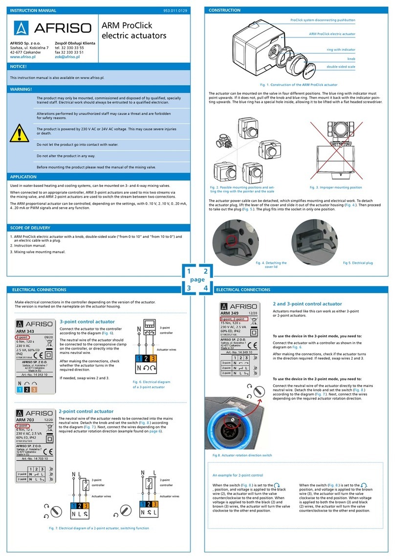
BA SYSTEMS BAS 918S User manual

BA Systems—Petershvilevej 1—DK-3200 Helsinge—http://www.basystems.dk
BAS 918S/929S Manual
Manual
BAS 918S/929S

BA Systems—Petershvilevej 1—DK-3200 Helsinge—http://www.basystems.dk 2
BAS 918S/929S Manual
Table of content
Introduction...............................................................................................................3
Materials included.....................................................................................................4
Product mount ..........................................................................................................5
Installation ................................................................................................................6
Terminals description.............................................................................................9
Functional description ..........................................................................................10
Option Module connection ...................................................................................14
Modbus................................................................................................................15
BACnet ................................................................................................................15
BAS918S configuration........................................................................................16
BAS929S configuration........................................................................................17
Scheme list ..........................................................................................................18
Scheme introduction ............................................................................................19
Scheme 1, Central heating...................................................................................20
Scheme 2, Central heating and Hot water tank....................................................26
Scheme 3, Central heating with Heat Exchanger .................................................35
Scheme 4, Central heating with Heat Exchanger and Hot water tank ..................41
Scheme 5, Dual Central heating ..........................................................................50
Scheme 6, Dual Central heating with Heat Exchanger.........................................58
Basic Controller operation.......................................................................................66
Menu structure.....................................................................................................66
Scheme selection ................................................................................................67
Scheme activation ...............................................................................................68
Regulation mode..................................................................................................69
Scheme setup......................................................................................................70
Info Screen .........................................................................................................72
Watch Screen ......................................................................................................72
Setup for IP access.................................................................................................73

BA Systems—Petershvilevej 1—DK-3200 Helsinge—http://www.basystems.dk 3
BAS 918S/929S Manual
Introduction:
Thank you for choosing a BAS 918S/929S controller.
Please make sure that you have received the correct
controller version and all the materials included.
The difference between the two controllers are only the
supported I/O. Please look at the following illustrations.
The controller is scheme-based. This means that a set
of preinstalled control schemes may be selected. Each
scheme is shown as a process diagram named
Scheme. The installation to be used is the selected.
Once a scheme has been selected it can be
customized. Please see the description of the different
schemes later in this manual.
On the next pages in this manual you will be guided
through the physical installation and maneuvering
the single button user interface.
Technical data
Power supply 24VAC/DC or 240VAC
Power < 6W
Digital outputs Solid state relay
BAS918S: 6 channals
BAS929S: 11 channels
Max 1A ved 240VAC/DC, must
be protected against inductive
loads.
Thermal Storage -20 °C to +70 °C
Operational -10°C to +60°C
Analog outputs BAS918S: 2 channals
BAS929S: 4 channals
Port 1..4: 0/2-10VDC
Port 3,4:, 0/4..20mA
Humidity Max. 90% RH,
Non condensing
Analog inputs BAS918S: 8 channals
BAS929S: 10 channals
Port 1..10: 0-1600 ohm (PT1000)
Port 1,3,5,7,9,10: 0/2-10V
Port 9,10:0/4-20 mA DC
Port 9,10:0..44900 ohm (NTC)
Mechanical ABS/PC, IP21
115.4 x 185.7 x 53 mm
570 g
Communication 10/100 Mbit ethernet
USB-Host or USB-Device
Optional internal module:
KNX, LON, MBUS, WMBUS
eller RS485
Real time clock ±12 minutter pr year at 20°C.
The RTC can run more than
1 year without power
applied. Can be adjusted
over the IP (ethernet)
connection, either directly or
through the SCADA system.
Digital inputs 4 x potential free contacts or max
12VDC.
User interface 3.5 inch colorscreen and
two-way scroll wheel with
pushbuttom select.

BA Systems—Petershvilevej 1—DK-3200 Helsinge—http://www.basystems.dk 4
BAS 918S/929S Manual
Materials included:
1. Produkt socket
2. Produkt front
3. 4 pcs. of , 3.9mm x 32 mm screws for wall mount
4. Cable relief bracket for cable retention at socket
5. 2 pcs. of 3.0mm x 8 mm screws for cable relief bracket mounting (4)

BA Systems—Petershvilevej 1—DK-3200 Helsinge—http://www.basystems.dk 5
BAS 918S/929S Manual
Product mount:
The socket (1) may be wall mounted using 4 screws (3). Cable insertion may be done form
behind into the socket or from the connector end of the front. See illustration below.
Cut out area when
cables inserted
from behind
Cut out area when cables inserted
from this end
Use a sharp knife to cut the plastic along or within the lines of the markings. When
cutout is made in the connector end of the front, cables are inserted here and may be
retained in the socket using the cable releif bracket.
screw (3)
screw (3)
screw (3)
screw (3)
Cable relief bracket

BA Systems—Petershvilevej 1—DK-3200 Helsinge—http://www.basystems.dk 6
BAS 918S/929S Manual
Installation:
Generic socket connections are defined in placement and function in the following draw-
ings and descriptions.
This indicates the maximum I/O configuration for the BAS9XXS controller. Please note
that the variant you have bought may have reduced configuration.

BA Systems—Petershvilevej 1—DK-3200 Helsinge—http://www.basystems.dk 7
BAS 918S/929S Manual
Controller profile:

BA Systems—Petershvilevej 1—DK-3200 Helsinge—http://www.basystems.dk 8
BAS 918S/929S Manual
Controller front:
Dimensions for wall mount are indicated from above drawing.

BA Systems—Petershvilevej 1—DK-3200 Helsinge—http://www.basystems.dk 9
BAS 918S/929S Manual
Terminal descriptions:
Terminal
label
Definition Notes
240VAC 2 terminals
N = Nul
L = phase (Line)
100V-240V AC, 50Hz or 60Hz
Power supply. May be substituted by
24VAC or 24VDC
24VAC/DC 2 terminals
N = Nul / DC-
L = fase / DC+
24VAC, 50Hz - 60Hz or 24VDC, minimum 10W
When connected, 240VAC is discon-
nected in the controller internally.
May supply 24VDC/4W when
240VAC is sourcing power.
DOX (1-11) 2 terminals per I/O channels, Electronic relay. No
polarization required.
AC or DC
maximum 240VAC @ 1A
maximum 400VDC @ 1A
3750V Rms isolation
DIX (1-4)
DICOM
Potential free contact inputs with one common termi-
nal (DICOM) to be used in relation with each DIX
terminal.
DICOM is a 5V DC voltage, sourc-
ing maximum 50mA out. Protected
against voltage inputs up to +75V
peak. AC voltage protection only by
resistive fuse.
STPB 4 terminals for Stepper motor connection, maximum
4W drive capability. Up to 24V drive.
24VAC/DC power supply for extend-
ed drive capability. Max 20W pr
channal.
STPA Secondary Stepper motor connection. As above. 2 terminals combined with AO cur-
rent output capability. Not coexist-
ing, i.e. controller mounted with ei-
ther AO current output or second
stepper motor capability
OPX (1-3) 3 terminals for communication module support Module to be mounted from factory
and must be ordered when the con-
troller is ordered.
Modules available:
MBUS
RS485
KNX
LON
WMBUS
AOX (1-4) 2 terminaler for each analog output channel. Must be
polarized as indicated by + and – signs.
Output type
0/2-10V with max 10mA load
0/4 –20mA current loop, channel 3 and 4 only,
combined with Stepper motor output A.
When using current mode the – ter-
minal is still to be used at the primary
terminal block.
Protected against reverse polarity and
input voltages up to 40V
AIX (1-10) 2 terminals for each I/O channel. Must be polarized
as indicated by + and – signs.
Capability per I/O number:
Channel 1..10: 0-1600 ohm (PT1000)
Channel 1,3,5,7,9,10: 0/2-10V
Channel 9,10:0/4-20 mA DC
Channel 9,10:0..44900 ohm (NTC)
Protected against reverse polarity and
input voltages up to 40V.

BA Systems—Petershvilevej 1—DK-3200 Helsinge—http://www.basystems.dk 10
BAS 918S/929S Manual
Functional description:
Power supply
The Controller is supplied by the terminals 240VAC, accepting 90VAC-264VAC, 50Hz - 60Hz.
or
By the terminals 24VAC/DC, accepting 24VAC/50Hz/10% and alternatively 24VDC/25%.
If both power inputs are connected, the internal circuit will select the 24V source. The 240V
source is then disconnected internally.When 240VAC supply is used, the 24V pin set will
output 24V DC. Maximum power output is 4W.
In the center of the controller socket, 2 set of 10 pole terminal blocks are placed. By default all
terminals in each block has been shorted by a mounted shorting circuit (alternative circuits
can be ordered). The intension with this is to assemble Nul (-) and Phase (+) connections
internally distributing connections from here. Only one supply line into the controller is then
required. Alternative use will also apply.
Digital outputs
All ports are galvanic isolated from other channels as well as from the internal controlling
circuit. The circuit for one output (2 signal wires) is an Electronic relay, which may connect AC
or DC signals. This relay will apply a voltage drop of approximately 1V in closed state. When
operating a digital signal, this 1V drop may corrupt the signal level interpretation. In this case
a secondary relay must be inserted. Please see visualization below.
0
Circulation Pump
0-10V
RUN
.
DO2B
DOXB
D01B
BAS9XXS CONTROLLER
.
DOXA
D01A
DO2A
RUN
0
Circulation Pump
DO2B
0-10V
BAS9XXS CONTROLLER
.
DOXA
DOXB
D01B
D01A
DO2A
.
SECONDARY RELAY
3
1
2
4
24VAC/DC
0V
"DO" RELAY CONNECTED HAS
1V DROP OVER THE TERMINALS

BA Systems—Petershvilevej 1—DK-3200 Helsinge—http://www.basystems.dk 11
BAS 918S/929S Manual
Digital inputs
Intended for use as potential free contacts. A change in contact state can be measured, as
well as pulses from repeated state change, can be counted (from metering devices).
Maximum puls counting frequency is 25Hz. All inputs are galvanic connected, but isolated
from the internal controlling circuit. Typical connection seen below.
If more potential free contacts are to be mounted, one wire from each must be connected to
the ”DICOM” terminal.
Analog inputs
Please note the different configuration capabilities for each individual channel. More
information is seen on page 9. All channels are galvanic interconnected as well as connected
to the internal controlling circuit. An advantage of this is that there is only one common
reference.
As shown above, a 5 wire cable is sufficient for connection to 4 pcs of thermal sensors.
Please note though, that sensor calibration is recommended because of increased voltage
drop over the common reference.
Connect to DICOM
Connect to DI(X)
POTENTIAL FREE
CONTACT
Connect to DI1
Connect to DICOM
POTENTIAL FREE
CONTACT 1
POTENTIAL FREE
CONTACT 2
Connect to DI2
POTENTIAL FREE
CONTACT 3
Connect to DI3
POTENTIAL FREE
CONTACT 4
Connect to DI4
DI2
BAS9XXS CONTROLLER
DI3
DI1
DICOM
DI4
PT1000
PT1000
PT1000
PT1000
5 WIRE CABLE

BA Systems—Petershvilevej 1—DK-3200 Helsinge—http://www.basystems.dk 12
BAS 918S/929S Manual
Analog input continued
Note: It is not recommended to use a reference shared for sensor signals as well as
for Pumps, Valves or Motor loads. Also, current loop analog input signals must have a
dedicated reference connection. Analog inputs configured for voltage measurements may
have common reference.
When connecting 4 x PT1000, 2 x 0/4mA-20mA, 2 x 0/2V-10V minimum 12 wires will be
required.
If one cable is used for analog signals mixed with supply wires for pumps, valves or motors,
it may be necessary to use twisted pair cables to suppress noise. In this case each analog
input must have a specific reference wire twisted with the + analog input wire.
Example, connecting Pressure Transmitter:
PT1000
PT1000
PT1000
PT1000
12 WIRE CABLE
4-20mA
4-20mA
0-10V
0-10V
1
2
3
4
0-10V
4-20mA
0V
24VAC/DC
PRESSURE TRANSMITTER
TERMINALS
AI(X)-
AI(X)+
BAS9XXS CONTROLLER
SUPPLY CONNECTED AT THE
LOAD, TO AVOID DISTURBING
THE ANALOG MEASUREMENT
24V SUPPLY -
+

BA Systems—Petershvilevej 1—DK-3200 Helsinge—http://www.basystems.dk 13
BAS 918S/929S Manual
Analog outputs
BAS918S includes 2 channels, and BAS929S 4 channels. See table page 9.
All channels are galvanic interconnected as well as connected to the internal controlling
circuit. Channal 3 and 4 has voltage output on one set of terminals (AO{X}) and current loop
on another set (AO{X}_I). See page 15. The signal reference for 3 and 4 for voltage as well
as current loop terminals are located on AO3- and AO4-. For inspiration see the following
example.
Example, Motor Valve connection:
Stepmotor output ports
Is not available on the current versions of the BAS9XXS controllers. Please contact the
supplier for more information.
1
2
3
4
MOTOR VALVE
0V
24VAC/DC
0-10V
AO(X)-
AO(X)+
BAS9XXS CONTROLLER
REFERENCE VOLTAGE FOR ANALOG
INPUTS AND ANALOG OUTPUTS ARE
CONNECTED IN THE CONTROLLER, SO
ONE REFERENCE WIRE IS SUFFICIENT
24V SUPPLY
AI(X)+
POSITION
CONTROL
0-10V
+
-

BA Systems—Petershvilevej 1—DK-3200 Helsinge—http://www.basystems.dk 14
BAS 918S/929S Manual
Option modules
The controller may have an internal module mounted, enalbing different
communication interfaces over the ”OP” terminals or communicating wireless with an
antenna mounted. Currently the following modules are available
1. RS485
2. MBUS
3. Wireless MBUS (OMS)
4. LON
5. KNX
Cabled interfaces are all, except module 3, using OP1-3 terminals, see below.
Only authorized personel may do module mounting, So when requesting this option,
the controller must be ordered with this included, from the supplier.
Connection:
For cabled bus interfaces, below modules may be mounted.
MBUS
RS485
KNX
LON
As described previously, the terminals OP1-3 are used for connection. Below wiring
table defines how to connect.
Bus interfaces with differential signaling (all except MBUS) must use twisted pair cabling.
One pair for a bus interface, RS485, KNX or LON.
Terminal label MBUS RS485 KNX LON
OP1 BUS PLUS A (PLUS) BUS + NET A
OP2 - GND KEY (Short to
BUS- for configu-
ration mode)
-
OP3 -24V
(BUS MINUS)
B (MINUS) BUS - NET B

BA Systems—Petershvilevej 1—DK-3200 Helsinge—http://www.basystems.dk 15
BAS 918S/929S Manual
MODBUS
Available parameters are shown for each controlling scheme.
The controller may be configured for Modbus/RTU via TCP/IP, or if a RS485 module is
mounted, Modbus/RTU via RS485. Communication parameters are 19200,n,8,1. Bus
ID and Bus impedance termination may be set in the controller ”information” menu.
For each scheme, a specific modbus parameter list is defined, The information is to be
interpreted according to below:
BACnet
Available parameters are shown for each controlling scheme.
The controller is always using BACnet port BAC0/47808 and is given the name
BAS9XXS Device.
The controller ID can be configured by the menu system, operated through the scroll
button. The ID is by default set to 1.
Holding Register The register to be addressed, read or write
Fcn 3/6 x10 Modbus Holding register read/write. The value must be divided by 10 to get
the physical value. I.e. 136 correlates to 13.6. Remember to multiply by 10
if a value is to be written into the controller register.
Fcn 3/6 x1 As above without any scaling
Input Register The register to be read from
Fcn 4 x10 Modbus Input register read. The value must be divided by 10 to get the
physical value. I.e. 97 correlates to 9.7
Fcn 4 x1 As above without any scaling

BA Systems—Petershvilevej 1—DK-3200 Helsinge—http://www.basystems.dk 16
BAS 918S/929S Manual
BAS 918S configuration:

BA Systems—Petershvilevej 1—DK-3200 Helsinge—http://www.basystems.dk 17
BAS 918S/929S Manual
BAS 929S configuration:

BA Systems—Petershvilevej 1—DK-3200 Helsinge—http://www.basystems.dk 18
BAS 918S/929S Manual
Scheme list:
For every controlling scheme loaded into the controller, the following sections will define a
process diagram, cabling according to this and a description of Modbus parameters availa-
ble.
The list below defines available schemes:
1. Central heating
2. Central heating and Hot water tank
3. Central heating with Heat Exchanger
4. Central heating with Heat Exchanger and Hot water tank
5. Dual Central heating
6. Dual Central heating with Heat Exchanger

BA Systems—Petershvilevej 1—DK-3200 Helsinge—http://www.basystems.dk 19
BAS 918S/929S Manual
Scheme introduction:
Outdoor sensor
Is a global parameter, defined as
When connected to one controller, the value will be available for all controllers in
the network (same IP segment).
Local sensor fault, will be compensated by using a sensor available in the
network.
If no local sensor fault, the local sensor value will be used.
Sensor fault will only be displayed if neither local nor global sensor are detected.
Only one outdoor sensor is required for an installation.
Scaling
For metering applications, a conversion factor must be defined. This is called scaling. So
when a controlling scheme is selected, a scaling factor may be requested before it can be
actvated.
Important: Scaling setup for the controller and the metering unit must be identical.
Water metering
Water metering in the following control scemes is optional. Scheme selection therefore
includes of water metering ”on” or ”off” selection.
Symbol description
Symbol Description
Flow meter
Modulation control valve
Outdoor temperature sensor
Gate valve
Pump
Temperature sensor
Hot water tank with temperature sensor
Heat exchanger
Pressure transmitter

BA Systems—Petershvilevej 1—DK-3200 Helsinge—http://www.basystems.dk 20
BAS 918S/929S Manual
Scheme 1, process diagram:
Central heating (CH)
BAS918S or BAS929S
AI3
AI1
AI2
DI1
DO1
AO1
This manual suits for next models
1
Table of contents
