PRODUCT BULLETIN
MGS-402 24V External Power Supply
1100-1092tttttttttttttttttttttttttttttttttttttttttttttttttttttttttttttttttttttttttttttttttttttttttt Bacharach |myBacharach.com | 2
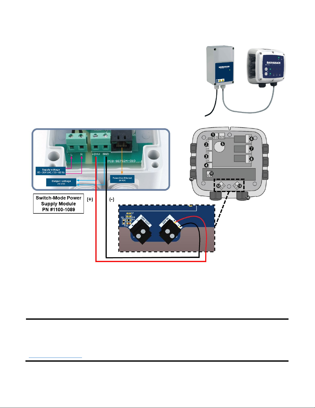
3.5 Power Wiring
The MGS-402 Controller 24V DC will ONLY work if powered via 24V
DC derived from an external power source.
Bacharach Switch-Mode Power Supply Module (PN #1100-1089) is
recommended to supply the unit with power.
Please use the below wiring diagram when wiring the Switch-Mode
Power Supply Module (PN #1100-1089) to an MGS-402 Controller.
Locate the +24 VDC input terminal block (#13) and unplug it from the controller.
1. Ensuring that the main power is turned off at the upstream circuit breaker or disconnect switch,
feed the incoming power leads through the right-hand M20 gland and into the appropriate
terminals (+24 VDC and -24VDC) on the terminal block.
2. Plug the +24 VDC terminal block back into the printed circuit board (PCB).
Bacharach recommends using 0.75mm2(18AWG) cabling, at minimum, when wiring power between
the Switch Power Supply Module (PN #1100-1089) and an MGS-402 Controller.
Max cable length will vary depending on the application and the number of controllers and detectors
powered via the power supply. See the MGS Series Cable Sizing & Selection Guide for more details,
https://bit.ly/33PnBe9
For additional MGS-402 wiring and installation instructions, please reference the MGS-402 User Manual
PN #1100-2578.


