Ribcage Installation: Part 2 - Assembly
www.back-bone.ca | support@back-bone.ca
1
Contents
Section 1 – Before You Get Started .............................................................................................................. 2
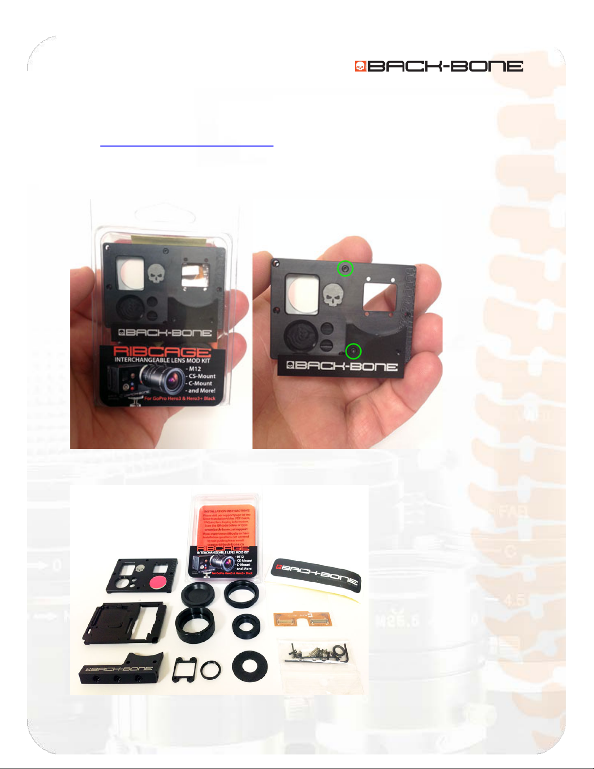
Included With Your Kit: ............................................................................................................................. 2
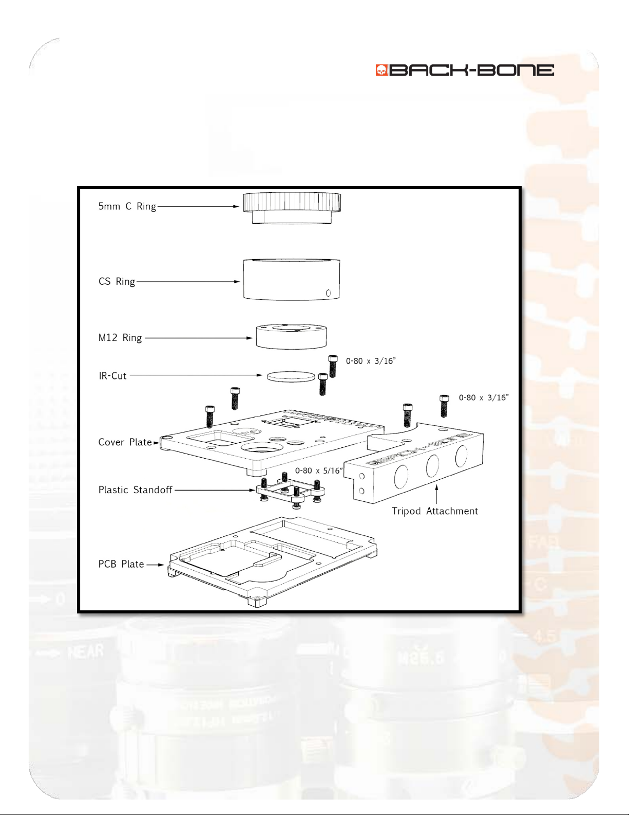
Figure: A .................................................................................................................................................... 3
CAUTION! .................................................................................................................................................. 4
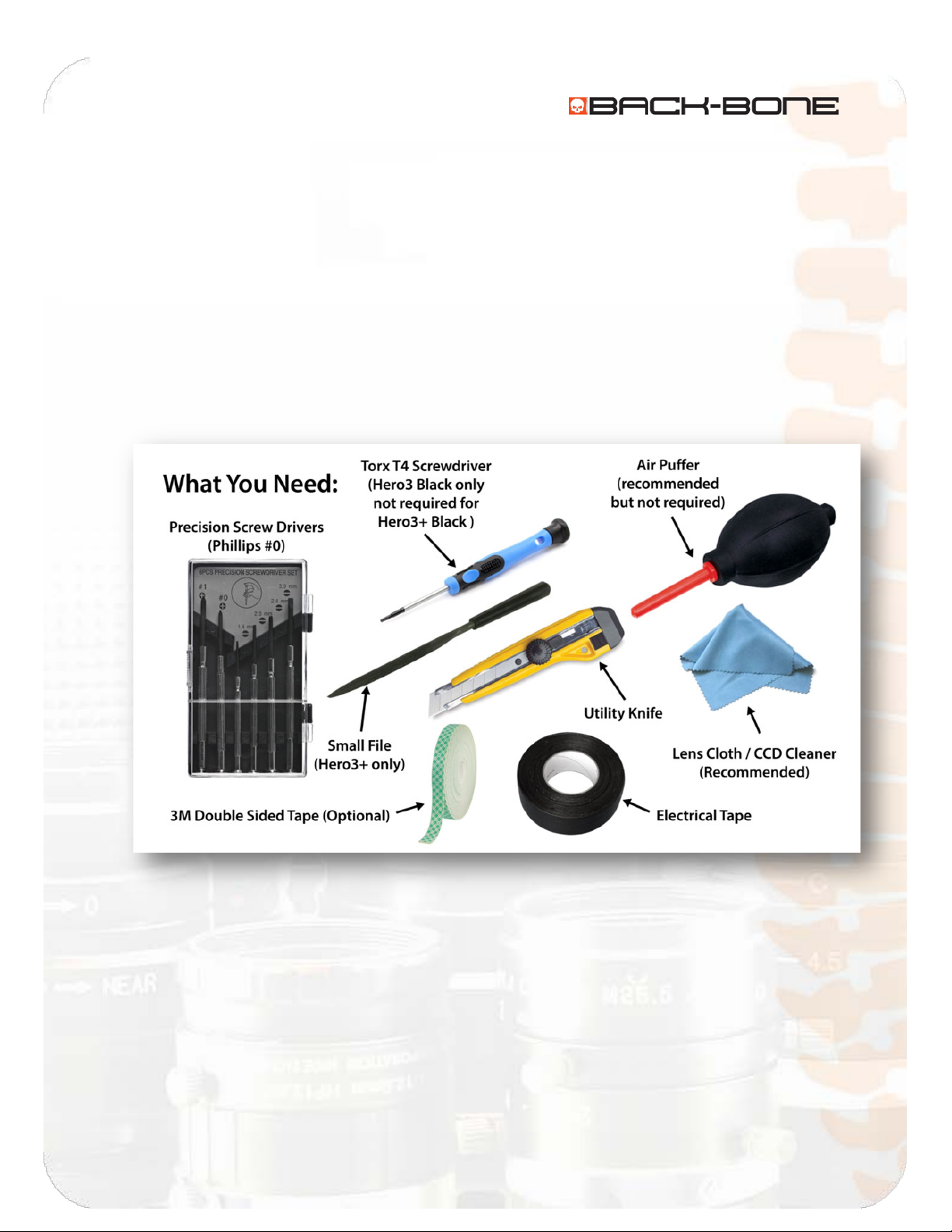
Tools Required .......................................................................................................................................... 5
Section 2: Ribcage Assembly......................................................................................................................... 6
2-1 Your Ribcage Kit .................................................................................................................................. 6
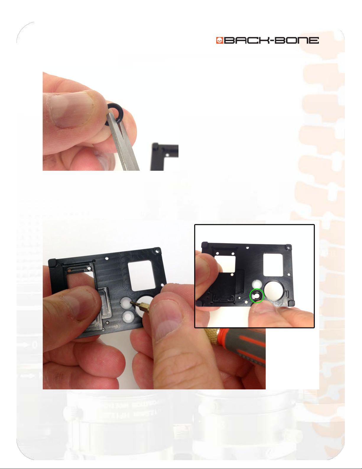
2-2 Transfer the LED and power buttons.................................................................................................. 7
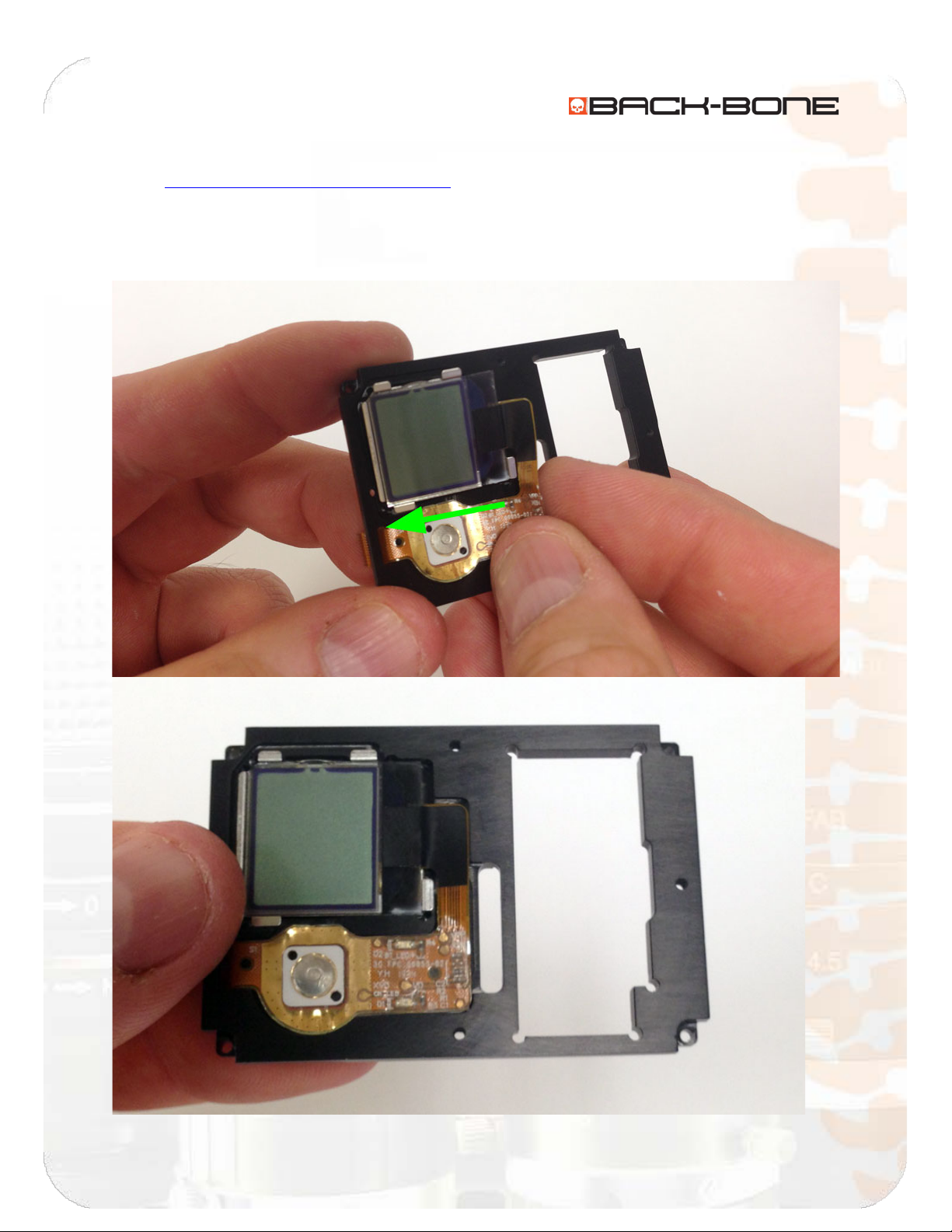
2-3 Attach LCD/Button Strip ..................................................................................................................... 9
2-4 Attach CMOS Sensor to Cover Plate ................................................................................................. 10
Permanent IR-Cut Placement (Fig. A) ................................................................................................. 13
Removable IR-Cut Placement (Fig. B) ................................................................................................. 13
2-5 Attach the Cover Plate to the PCB Plate...........................................................................................16
2-6 Connect flexible PCB jumper to PCB plate........................................................................................17
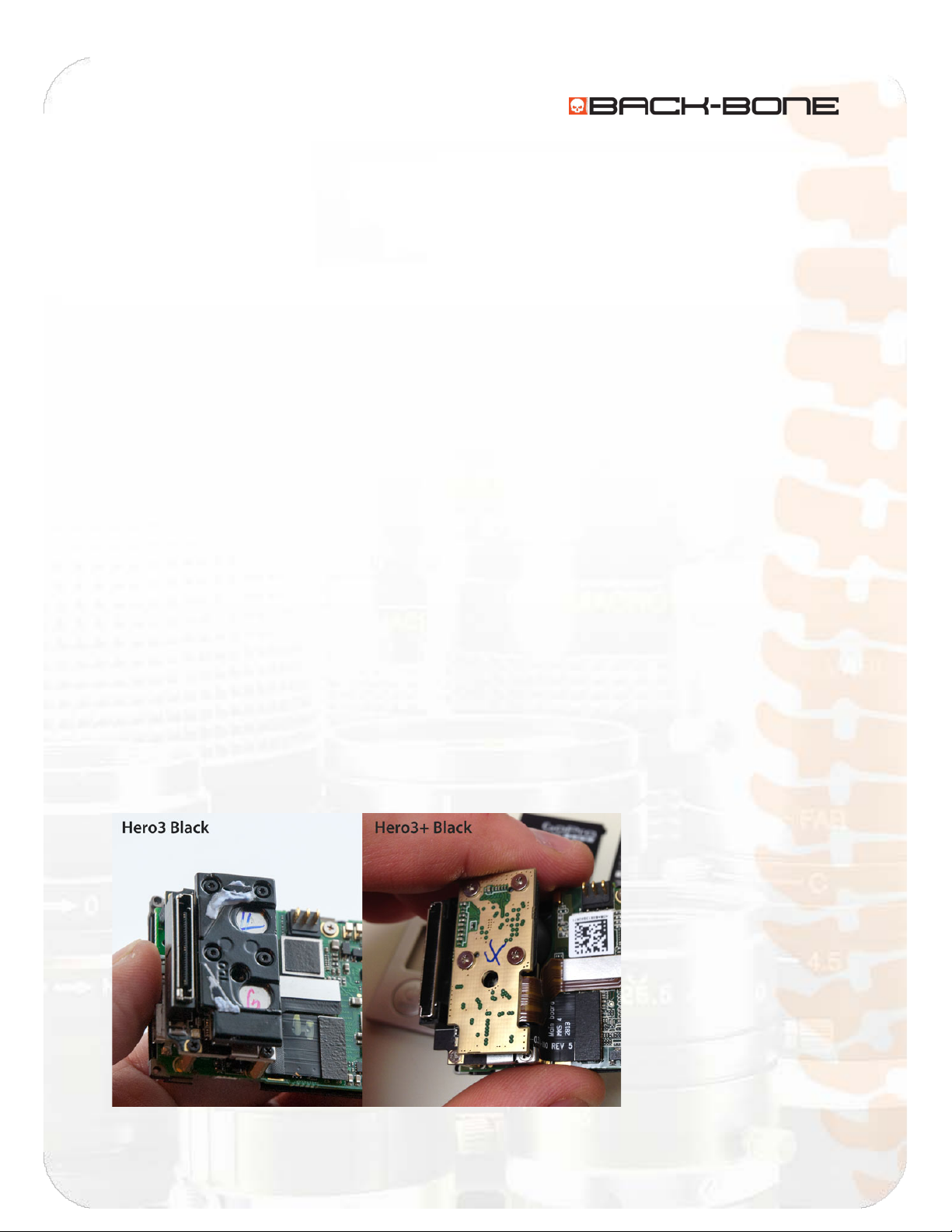
A Note for Hero3+ Installations: .........................................................................................................19
2-7 Functionality Test..............................................................................................................................24
2-8 Put Ribcage Assembly Back Into Housing .........................................................................................25
2-9 Release Cover Plate Screws .............................................................................................................. 26
2-10 Insert Original Corner Screws .........................................................................................................27
2-11 Screw on Cover Plate ...................................................................................................................... 28
2-12 Insert Set Screw Into M12 Ring ...................................................................................................... 30
2-13 Attach CS-Mount Ring..................................................................................................................... 31
2-14 Re-attach Battery and Accessories .................................................................................................33
2-15 Install IR Cut Filter and Holder........................................................................................................ 34
2-16 Attach C-Mount Ring ...................................................................................................................... 35
2-17 Attach Tripod Mount ......................................................................................................................36
2-19 Done! .............................................................................................................................................. 37