Backbone Ribcage v2.0 User manual

Ribcage v2.0 Upgrade Kit
Install Guide
Back-Bone
V2.0

Ribcage Installation: Part 2 - Assembly
www.back-bone.ca | support@back-bone.ca
1
Contents
Included With Your Kit: ............................................................................................................................. 2
Figure: A .................................................................................................................................................... 3
CAUTION! .................................................................................................................................................. 4
HELP! ......................................................................................................................................................... 4
Tools Required .......................................................................................................................................... 4
Section 1: Disassembly.................................................................................................................................. 5
1-1 Remove Tripod Mount and Accessories ............................................................................................. 5
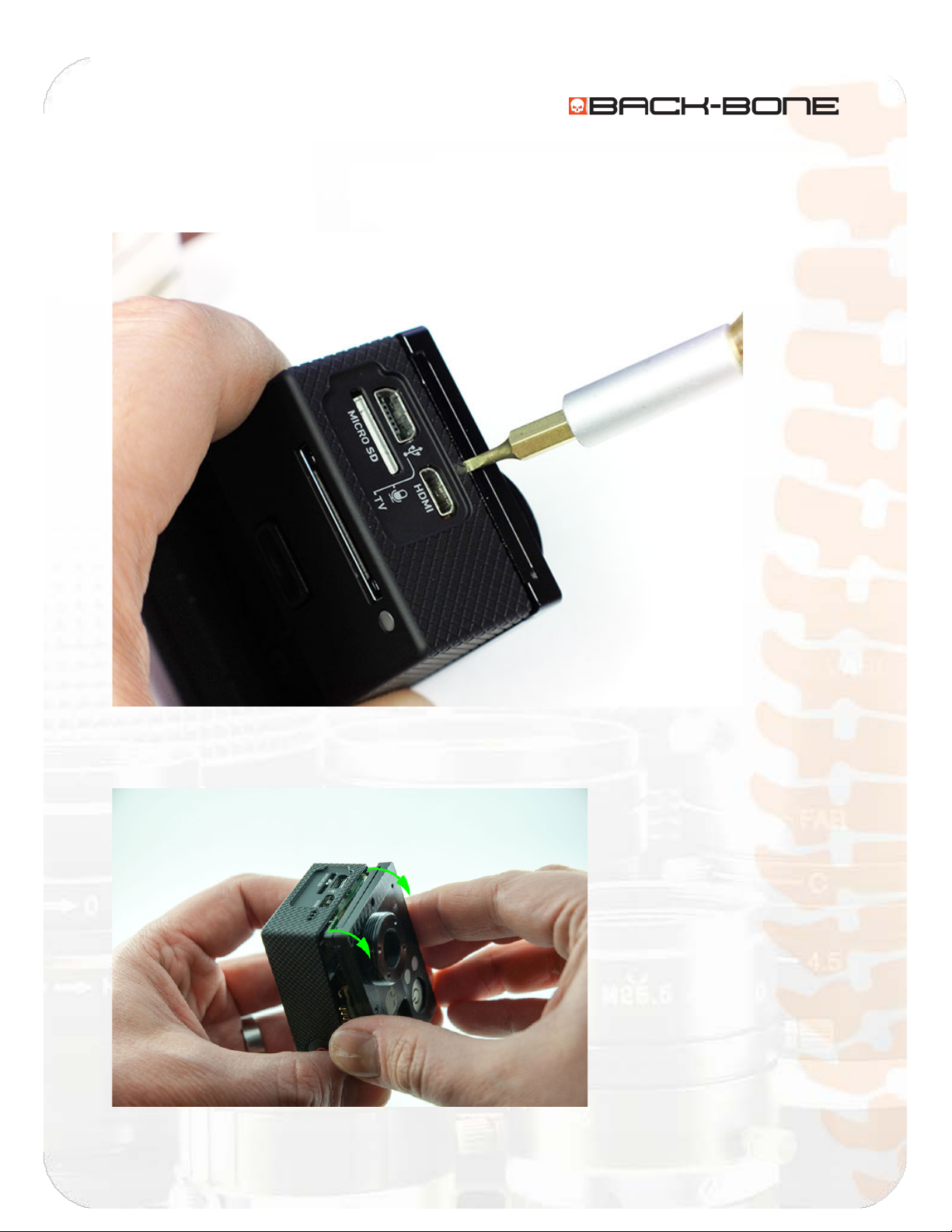
1-2 Remove Cover Plate Screws ............................................................................................................... 6
1-3 Remove Assembly From Housing ....................................................................................................... 8
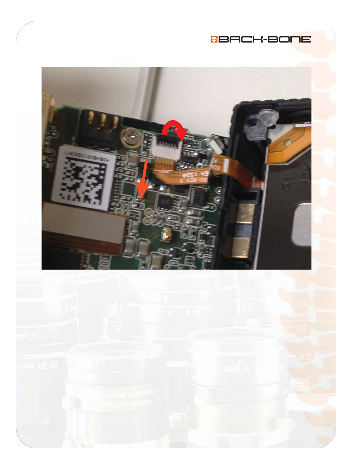
1-4 Disconnect Image Sensor.................................................................................................................. 10
1-5 Remove Main Board .........................................................................................................................11
1-6 Remove M12 Ring.............................................................................................................................13
1-7 Remove Image Sensor and Standoff................................................................................................. 14
Section 2: Assembly ....................................................................................................................................15
2-1 Insert O-Ring .....................................................................................................................................15
2-2 Attach CMOS Sensor to Cover Plate .................................................................................................16
2-3 Attach the Cover Plate to the PCB Plate...........................................................................................20
2-4 Connect flexible PCB jumper to PCB plate........................................................................................ 21
2-5 Functionality Test..............................................................................................................................28
2-6 Put Ribcage Assembly Back Into Housing .........................................................................................29
2-7 Release Cover Plate Screws .............................................................................................................. 30
2-8 Insert Original Corner Screws ...........................................................................................................31
2-9 Screw on Cover Plate ........................................................................................................................32
2-10 Install the IR-Cut Filter .................................................................................................................... 34
2-11 Attach the Mounting Rings ............................................................................................................. 40
2-14 Re-attach Battery and Accessories .................................................................................................43
2-15 Attach Tripod Mount ...................................................................................................................... 44
2-12 Done! .............................................................................................................................................. 45

Ribcage Installation: Part 2 - Assembly
www.back-bone.ca | support@back-bone.ca
2
Section 1 – Before You Get Started
Included With Your Kit:
ITEM DESCRIPTION QUANTITY
1. 650nm IR-cut filter 2
2. M12 ring 1
3. Plastic standoff 1
4. IR-Cut Holder 2
5. Filter Stickers 4
6. L-key 0.050” Hex 1
7. L-key 0.035” Hex 1
8. 0-80 x 1/4” Philips screw 4
9. Nylon tip set screw 1
10. Rubber O-Ring 1

Ribcage Installation: Part 2 - Assembly
www.back-bone.ca | support@back-bone.ca
3
Figure: A

Ribcage Installation: Part 2 - Assembly
www.back-bone.ca | support@back-bone.ca
4
CAUTION!
1. Read all our documentation thoroughly before beginning your installation
2. Make sure to charge your battery before beginning the installation.
3. NEVER force or exert force on any components. IF YOU FEEL THE NEED TO USE FORCE THAN
YOU’RE DOING SOMETHING WRONG.
4. The Ribcage DIY kit consists of highly machined parts and fine threaded through holes. NEVER
FORCE any screws as this can strip the fine threads on the through holes. Instead check your
assembly and registration and try again. All parts are highly accurate and DO NOT require force
to assemble.
5. Ensure your work area is clean, well lit and free from dust.
6. We recommend inspecting and removing any dust or debris from the parts before you begin.
7. Never over over tighten any of the small screws, especially on the faceplate and tripod mount.
Excessive force or over tightening can result in stripped threads on the aluminum parts. Always
loosely fit all screws in place before screwing them in until seated. Additional tightening is not
required.
8. By applying this or any modifications to your GoPro devices you will VOID any warranties
9. Back-Bone takes no responsibility in your ability to use this modification
10. The Ribcage v2 Upgrade kit is provide “as is” and without warranty
11. Disclaimer: Ribcage is a product of Back-Bone Gear Inc., and is not manufactured, distributed or
endorsed by Woodman Labs, Inc. the maker of GoPro and Hero Products.
HELP!
If at any point during the process you experience trouble please contact us at support@back-bone.ca
and someone will help you through your problem. It’s best to contact us first before causing damage!
Our support email address is located on the bottom of every page. Our staff are on duty 9am-5pm EST
Mon-Fri to answer questions, and we will often respond outside those hours.
Tools Required
Before you begin you will need to gather the following tools:
•A Torx T4 screw driver (not required for Hero3+)
•A set of small precision screw drivers with a Philips #0
•Lens / CCD Cleaner, Puffer & Lens Cloth (Optional but recommended)
•A utility knife
•A pair of scissors (optional)
•A roll of electric tape
•3M Double Sided Tape (Optional) Note: don’t use thick mounting tape – use only very thin
double sided tape or the parts may not fit correctly.

Ribcage Installation: Part 2 - Assembly
www.back-bone.ca | support@back-bone.ca
5
Section 1: Disassembly
1-1 Remove Tripod Mount and Accessories
Let’s start by removing the optional parts from your camera. Remove the battery and memory card.
Next use your own tools or the larger of the two L-keys that came with your kit or camera to remove the
screws holding on the tripod mount. (0.050” Hex)
Remove the 5mm C-Mount spacer ring. Use your small L-Key (0.035” Hex) to loosen the set screw on the
large CS-Mount ring. Unscrew the ring to loosen. Turn the camera so that the front is facing the floor.
Continue to unscrew the ring until it comes free. The IR-cut filter should drop into the CS-ring and plastic
holder. Set the rings aside.

Ribcage Installation: Part 2 - Assembly
www.back-bone.ca | support@back-bone.ca
6
1-2 Remove Cover Plate Screws
Loosen and remove the 4 screws holding on the Ribcage faceplate.
Lift the plate slightly and rotate about 10 degrees to reveal the four corner mounting screws. Use your
screwdriver to loosen and remove all four screws. Make sure to keep them for later. Remove the power
button if it hasn’t come out on its own. Rotate the cover plate back into position.

Ribcage Installation: Part 2 - Assembly
www.back-bone.ca | support@back-bone.ca
7
Fasten the cover plate back down with one or two of the screws you removed.

Ribcage Installation: Part 2 - Assembly
www.back-bone.ca | support@back-bone.ca
8
1-3 Remove Assembly From Housing
Insert a small flat screw driver into the small slot located between the faceplate and the USB/HDMI
ports. Use it to pop the edge of the housing up over the USB and HDMI ports.
Gently wiggle the unit to work it out of the housing, taking care not to damage the tiny ribbon cable
connecting the assembly to the housing.

Ribcage Installation: Part 2 - Assembly
www.back-bone.ca | support@back-bone.ca
9
To disconnect the ribbon, flip up the black locking tab and slide the end of the ribbon out of the socket.

Ribcage Installation: Part 2 - Assembly
www.back-bone.ca | support@back-bone.ca
10
1-4 Disconnect Image Sensor
The tab connecting the image sensor ribbon to the main board is covered by a small piece of electrical
tape. Gently remove the tape.
Gently lift the lower right hand corner of the connector with your fingernail or a slim non-metallic tool. A
small amount of upward pressure should pop the connector free.

Ribcage Installation: Part 2 - Assembly
www.back-bone.ca | support@back-bone.ca
11
1-5 Remove Main Board
Unlock the black locking tab holding in the LCD connector on the lower right. Gently use your screw
driver to pull the end of the connector from the socket.
Remove the small metallic screw holding the main board in position.

Ribcage Installation: Part 2 - Assembly
www.back-bone.ca | support@back-bone.ca
12
Next remove the main board by lifting it and moving it down and away from the CCD ribbon that was
disconnected earlier.

Ribcage Installation: Part 2 - Assembly
www.back-bone.ca | support@back-bone.ca
13
1-6 Remove M12 Ring
Pull up on the tape holding down the Ribbon connector to reveal the four screws that hold the M12 ring
in position. Depending on the date your camera or kit was purchased there is a slight variation in the
appearance but the following steps are the same for both.
Loosen each of the screws until the M12 ring comes free, but do not remove the screws. Depending on
the version of the kit used you will need either a Philips #0 screw driver or the larger of your two L-keys.
If the metal plate holding the image sensor has an open back take care not to dislodge the image sensor
as it will become loose once the M12 ring is removed. When lifting the unit hold the sensor in place
from the back with your finger.

Ribcage Installation: Part 2 - Assembly
www.back-bone.ca | support@back-bone.ca
14
1-7 Remove Image Sensor and Standoff
Finally remove the image sensor from the cover plate. Remove the original plastic standoff and the four
screws as we’ll be using the new ones provided in your upgrade kit.
**At this point it’s a great time to clean your CMOS sensor if any debris or smudges are visible.
NOTE:
At this point you may find it useful to view our v2 assembly video. Some of the steps are
not required but all of the steps outlined in the document going forward are pictured.
Links to relevant sections of this video are provided at the beginning of each section.
http://youtu.be/I1kAaRuEa3o?t=9m36s

Ribcage Installation: Part 2 - Assembly
www.back-bone.ca | support@back-bone.ca
15
Section 2: Assembly
2-1 Insert O-Ring
Video: http://youtu.be/I1kAaRuEa3o?t=9m36s
Take the supplied rubber O-ring and cut it in half with a pair of scissors or a utility knife. These will
prevent the LED covers from being accidentally pushed back into the camera after re-assembly.
Place each half of the O-ring behind the LED covers in the faceplate.

Ribcage Installation: Part 2 - Assembly
www.back-bone.ca | support@back-bone.ca
16
2-2 Attach CMOS Sensor to Cover Plate
Video: http://youtu.be/I1kAaRuEa3o?t=10m41s
(PLEASE READ THIS ENTIRE SECTION BEFORE PROCEEDING)
You will now need the tools and screws provided in the kit. Place the new plastic standoff over the
image sensor. If you look closely, you will notice that one side of the plastic standoff is smoother than
the other. The smooth side should face forward when placed over the sensor. If you find threading the
screws difficult, flip the plastic standoff over and try again. You can also thread the screws through the
standoff first and then remove them to make this step easier. Take care not to touch the image sensor
during the following steps, but if you do it can be cleaned later.

Ribcage Installation: Part 2 - Assembly
www.back-bone.ca | support@back-bone.ca
17
Screw in four of the long silver screws provided through the holes in the back of the image sensor board
and through the standoff.
Insert the image sensor with the plastic standoff back into the Ribcage cover plate so that the four holes
line up correctly.

Ribcage Installation: Part 2 - Assembly
www.back-bone.ca | support@back-bone.ca
18
Ensure that three of the four screws are flush with the front of the cover plate. The fourth screw should
extend beyond the cover plate slightly for attaching the M12 ring.
Position the M12-ring with its set screw hole towards the top.Screw the first socket screw into the M12-
ring, but do not tighten it. It’s important that the ring is flat against the plate as you engage the screws
to ensure that no gap is present behind the ring when complete. With the first screw loosely in
position, turn the M-12 ring to align the remaining three holes with the holes in the cover plate.

Ribcage Installation: Part 2 - Assembly
www.back-bone.ca | support@back-bone.ca
19
Lastly, we will gently in a repeating crisscross fashion tighten all 4 screws until the M-12 ring lays flush
with the cover plate and the 4 screws are snug ONLY i.e. tighten only to the point of contact. Before
continuing make sure there are no gaps behind the ring and it sits perfectly flat on the surface
If you plan to use M12 lenses similar to the original GoPro lens, insert the tiny set screw from your
original M12 ring into the top of the new M12 ring using the small L-key provided.
Table of contents
Other Backbone Camera Accessories manuals