3 Technical Description
3.1 Intended Use
Thes::canmicro::stationandnano::stationaredesignedforonlinemonitoringofwaterqualityparameters.The
requiredcomponents(probes,sensorsandoperatorterminal)aremountedwiththerequiredowcells,mounting
ttingsandpipeworkonacompactpanel.Thestationscanbeusedforrawwater,drinkingwater,tapwaterand
cleansurfacewater.Forwastewaterandwaterwithhighamountofparticlesaspecicmicro::stationwithlarger
pipeworkandowcellsforwastewaterisavailable.
Inalltypesofapplications,therespectiveacceptablelimits,whichareprovidedinthetechnicalspecicationsin
therespectives::canmanuals,havetobeobserved.Allapplicationsfallingoutsideoftheselimits,andwhichare
notauthorisedbys::canGmbHinwrittenform,donotfallunderthemanufacturer’sliability.
Thedevicemustonlybeusedforthepurposedescribedinthismanual.Useinapplicationsnotdescribedinthis
s::canmanual,ormodicationofthedevicewithoutwrittenagreementfroms::can,isnotallowed.s::canisnot
liableforclaimsfollowingfromsuchunauthoriseduse.Insuchacase,therisksarethesoleresponsibilityofthe
operator.
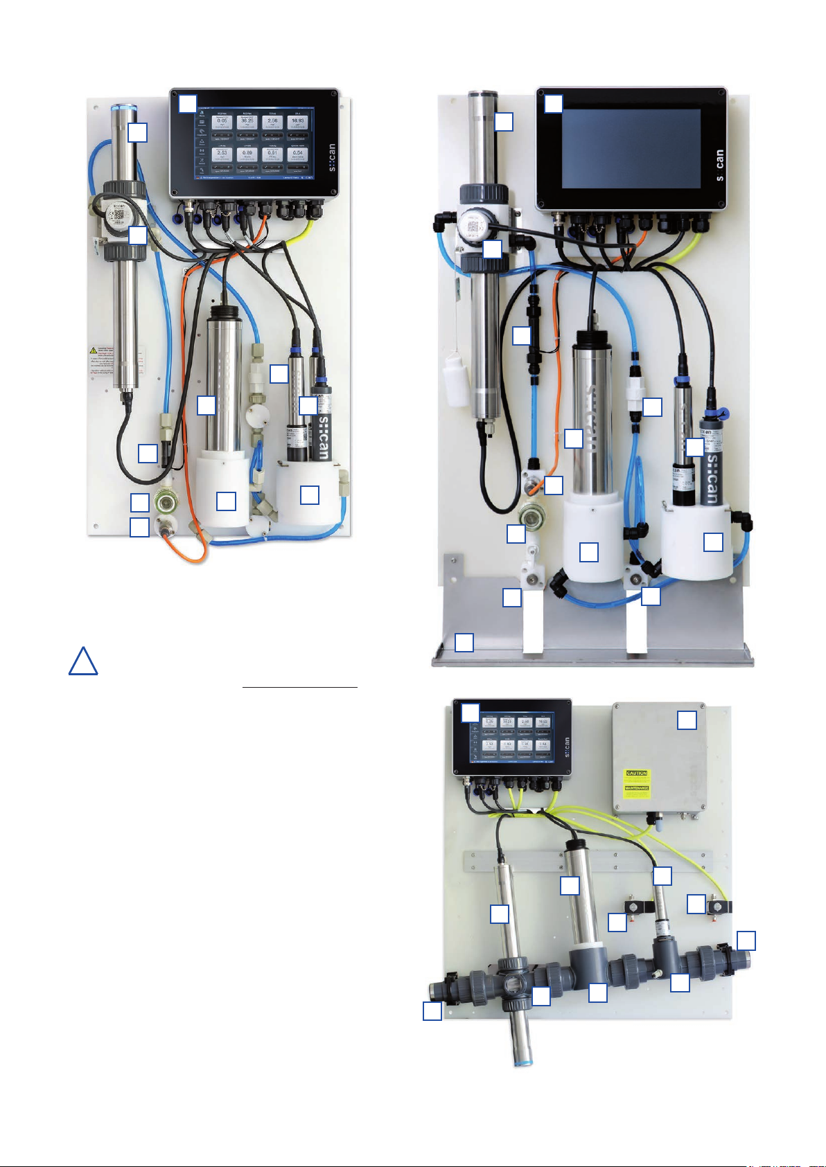
3.2 Functional Principle
All s::can stations are equipped with an inlet and outlet and designed for continuous discharge of the water
throughthedierentowcells.Aninletstrainerwillpreventparticlesfromenteringthestationandaowrestrictor
ensurescorrectpressureanddischarge.Aowdetectoralarmswhentheowistoolow.Thewaterleavesthe
stationpressure-free(freeatmosphere).Withthehelpofashut-ovalveaftertheinlet,theowcanbecompletely
shutoincaseofserviceactivities.
Optionalthestationcanbeequippedwithananalogpressuresensorandaseperatefeedpump.
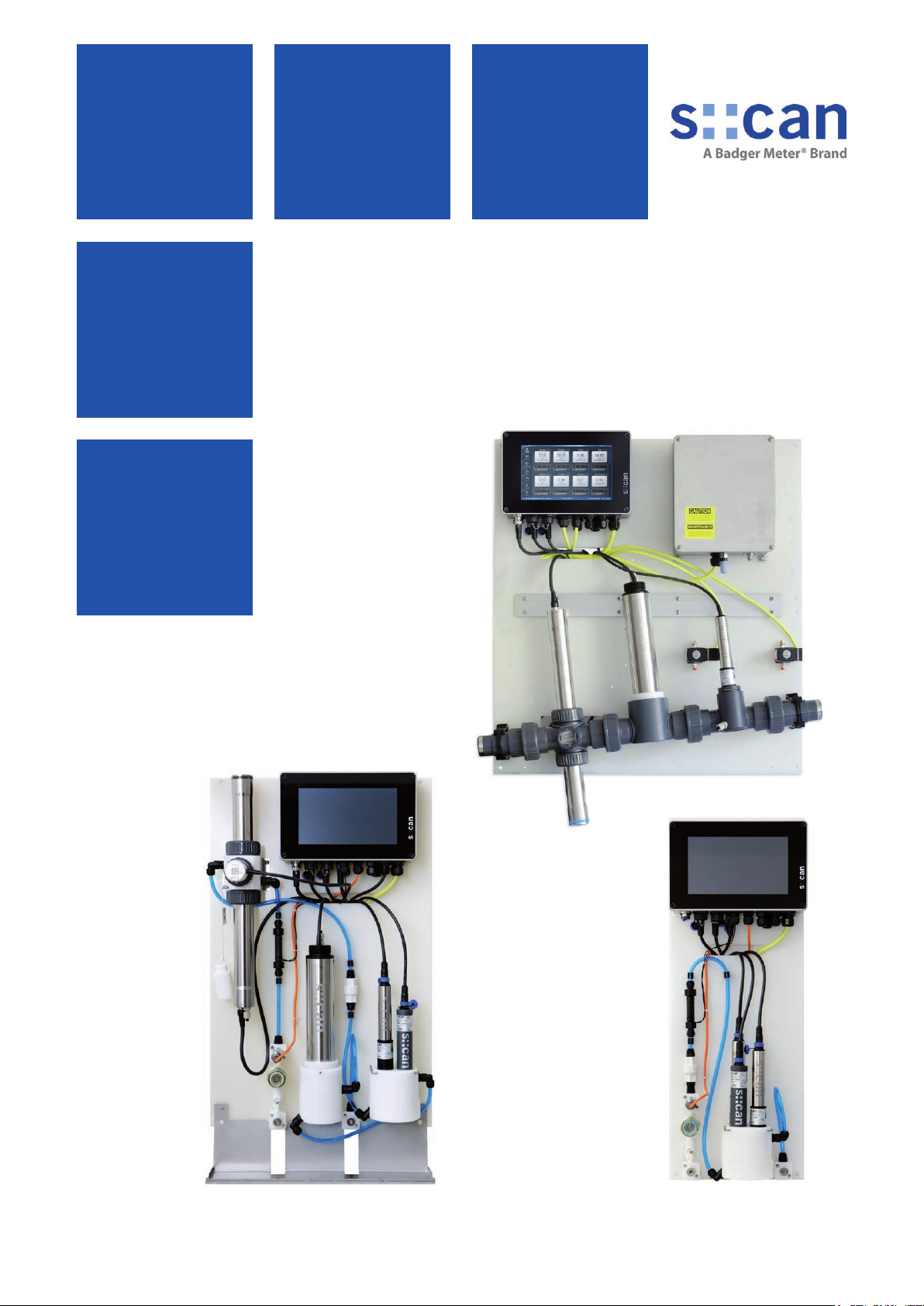
3.3 Product
Thefollowingvariantsofcompletelyassembledmonitoringstationsaswellassingelcomponentsofmonitoring
stationsareavailable.Regardingdetailedinformationofthestationspleaserefertosection9(accessories)as
wellasthetechnicalspecicationslocatedattheendofthismanual.Ifneeded,themonitoringstationscanbe
conguredcustomerspecicalso.
Type Specication
M-100-MICRO-S Turbidity,NO3,TOC,DOC,pH,EC,Temp,Alarms,mountedonpanelwith2ow
cells,autobrush,owdetectorandcon::cubeoperatorterminal;eventdetection
software included.
M-100-MICRO-M Turbidity,NO3,TOC,DOC,NH4-N,pH,Temp,Alarms,mountedonpanelwith2ow
cells,autobrush,owdetectorandcon::cubeoperatorterminal;eventdetection
software included.
M-100-MICRO-L Turbidity,NO3,TOC,DOC,pH,EC,Temp,onedisinfectionparameter,Alarms,
mountedonpanelwith2owcells,autobrush,owdetector,andcon::cubeopera-
torterminal;eventdetectionsoftwareincluded.
M-100-MICRO-XL Turbidity,NO3,NO2,TOC,DOC,pH,EC,2disinfectionparameters,Temp.,Alarms,
mountedonpanelwith2owcells,autobrush,owdetector,andcon::cubeopera-
torterminal;eventdetectionsoftwareincluded.
micro::station / nano::station, 03-2023 Release
www.s-can.at
Copyright © s::can GmbH
7 / 36