manuals.online logo
Brands
  1. Home
  2. •
  3. Brands
  4. •
  5. Badger Meter
  6. •
  7. Transceiver
  8. •
  9. Badger Meter 345WT User manual

Badger Meter 345WT User manual

BadgerMeter, Inc.
Installation &
Operation Manual
Badger®
Model 345WT Wireless Modbus/Pulse
Transceiver
941700-0017
10-08
2
TABLE OF CONTENTS
Overview.............................................................................. 2
Installation Checklist............................................................ 2
Hardware Overview............................................................. 2
Features .......................................................................... 2
Electrical Connections..................................................... 2
Hardware Connection...................................................... 2
Modbus Address.............................................................. 3
System Configuration...................................................... 3
Status LEDs .................................................................... 3
Signal Strength Test......................................................... 3
Modbus Overview................................................................ 3
Register Listing................................................................ 3
Register Functions .......................................................... 4
Firmware Update................................................................. 4
OVERVIEW
The Badger®Data Industrial®Model 345WT wireless Modbus/
pulse transceiver is designed to allow systems integrators the
ability to communicate with remote locations while avoiding
thecostsassociatedwithrunning lowvoltagewiringtomultiple
locationsinasingle orbetweenmultiplebuildings.Tomeetthese
requirements, the Model 345WT provides the installer with all
the tools necessary to install and configure the hardware and
software with a minimum of time and investment.
Installation Checklist
A Model 345WT system installation has the following compo-
nents:
Required hardware
• TwoormoreModel345WTtransceivers.
External hardware
• RS485ModbusmastersystemsuchasaModel3700
or a PLC.
• Optional:RS485/Modbusslavedevicessuchaspower
meters or IO modules.
• Optional: Pulse output transducers for measuring
gas, electricity, water, etc. from existing meters and
sensors. Make sure to obtain the pulse output scale,
or multiplier for each device you will be using.
Hardware Overview
Features
Processor 60MhzARM7.
LED 2xRF,2xRS485,2xpulse,Alive,Alarm
Communications RS485Modbus
RF 900MhzFrequencyHopping,ISMband,
 100mw
Rangeupto 1500ftindoordependingon 
obstructions
PowerRequirement110-120VAC
PowerSupply Included,9VDC,class2transformer
(included)
Pulse Inputs 2x dry contact (consumption/rate/min/
max)
Size 6.5"x4.5"x2"
Electrical Connection
Hardware Connection
Step 1 - Unpack materials:Remove all materials from ship-
ping box and verify all required components are
available.
Step 2 - Mount the Model 345WT on the wall or other ap-
propriate location.
Step 3 - Connect the pulse output devices.
Step 4 - Connect the RS485 Modbus terminals to your
Modbusdevices.Thiscanincludeeitherthemaster
devicesuchasanModel3700orPLC,anditcan
include a slave device such as a power meter.
Step 5 - Attach the antenna and power connector to the
Model 345WT.
3
Modbus Address
BeforetheBadger®DataIndustrial®Model345WTcanbeused,
youmustsettheModbusaddress.Thisaddressmustbeunique
among all Modbus devices in the system including all devices
that are connected on remote wireless links.
Select an address, and set the dipswitches to match.
The sum of the value of the switches is the address. In the
example to the right, address 52 is set by placing switch 4, 16
and 32 to the on position.
Note: 4 + 16 + 32 = 52
System Configuration
For most systems, set all of the system switches to the “off”
position.
Radio channel: This option selects the channel number that
can be used to isolate a group of Model 345WTs.
Programming: Set the Prog Enable and Prog RST En to Off
for normal operation.
Port RS232 or RS485: Set the switch to the Off position for
RS485operation.TheModel345WTcancommunicateviathe
RS232 connection, however, most Modbus devices will need
485terminals.
BaudRate:ThisoptionsetstheserialportspeedfortheModbus
devices connected to the Model 345WT. Set this option to Off
for19200.SettheswitchtoOnfor9600baud.
Reserved: Set this option to Off.
Status LEDs
The device should power up and be ready in a few seconds.
The LEDs should blink in the following manner.
•The Alive LED should start to blink about once per sec-
ond.
•The Alarm LED will blink when transmission errors occur.
•The RF TX/RX LEDs will blink when the radio is receiving
or transmitting data.
• TheRS485LEDswillblinkforlocalModbusactivity.
•The Pulse input LEDs will light when the corresponding
pulse input terminals are closed.
Signal StrengthTest
When the Model 345WT is operating, the Test button can be
usedtoreportthesignalstrengthreceivedbytheModel345WT
from another unit.
Press and hold theTest button. The status LEDs will light up as
abargraphdisplay.EachLEDisapproximately10%ofscale.
For example if PULSE 1 and 2 are on, the received strength is
approximately20%to29%.
For useful signal reporting, it is important to turn off all but
one other Model 345WT. When reporting the signal strength,
the most recent wireless transmission received is displayed.
If two Model 345WTs are transmitting, the display will only
show the most recently received packet, and the user will not
be able to determine which Model 345WT the signal strength
being reported.
NOTE:ThenormaloperationoftheModel345WTissuspended
while the test button is pressed. No pulses are counted,
Modbus communications and wireless transmissions are not
processed.
MODBUS OVERVIEW
Register Listing
offset point type desc
0 40001 UINT32 pulsecount1MSW
1 40002 UINT32 pulsecount1LSW
2 40003 UINT32 pulsecount2MSW
3 40004 UINT32 pulsecount2LSW(sameformat
as pulse count 1)
4 40005UINT16 instpulse1time(seconds)
5 40006UINT16 instpulse2time(seconds)
6 40007UINT16 (R/W)minpulse1time(seconds)
(write clears min/max)
7 40008UINT16 (R/W)minpulse2time(seconds)
8 40009UINT16 (R/W)maxpulse1time(seconds)
9 40010UINT16 (R/W)maxpulse2time(seconds)
10 40011UINT16 (R/W)instpulsecountsize.
(default 5)
100 40101 UINT16 SerialNumber(bytes1,2)(serial
number)
101 40102 UINT16 SerialNumber(bytes3,4)
102 40103 UINT16 SerialNumber(bytes5,6)
103 40104 UINT16 rmwareversion(e.g.v1.03,high
byte=major, lowbyte=minor,
  0x8000agsetforBeta)
104 40105 UINT16 bootcount
105 40106 UINT32 mfgdateMSW
106 40107 UINT32 mfgdateLSW
107 40108 UINT16 radiogroupidsetting(0-6)
108 40109 UINT16 alarmags(0x01=bootfrom
watchdog)
109 40110 UINT16 maxpacketbuffersused.
110 40111 UINT32 Radiouptime(seconds)MSW
111 40112 UINT32 Radiouptime(seconds)LSW
Due to continuous research, product improvements and enhancements, Badger
Meter reserves the right to change product or system specifications without notice,
except to the extent an outstanding contractual obligation exists.
BadgerMeter, Inc.
6116E.15thStreet,Tulsa,Oklahoma74112
(918)836-8411/Fax:(918)832-9962
www.badgermeter.com
Please see our website at www.badgermeter.com
for specific contacts.
Copyright©BadgerMeter,Inc.2008.Allrightsreserved.
Register Functions
Pulse Count: The pulse count is stored as an unsigned 32bit
integer. This allows for 2^32 pulses (4.2billion) to be counted
beforerollover.OnModbussystemsthatdonotallowyoutoread
32 bit values, you can calculate the pulse count as follows:
count = (MSW * 65535) + LSW
Instantaneous Pulse Rate:The pulse rate values for instan-
taneous, min and max rates are calculated based on the time
betweenarrivingpulses.Forexample,ifInstPulse1=30,and
instpulsecountsizeis5,thentheaveragerateforthelast5
pulses is 6 seconds per pulse. To convert the register values
(in seconds) to a rate value, use the following formula.
 RatePerHour=(N*60*60/Inst_Register)
Where InstRegister is any of the 6 register values 4 through 9.
Nistheinstantaneouspulsecountsizeatoffset10.
Min/Max pulse rate: These four registers are calculated from
the instantaneous pulse rate. These latching registers are
updated whenever the minimum or maximum rate fields are
exceeded by the instantaneous rate. These four registers may
beclearedbywritingazerototheregister.Writingtoonemin/
max register clears all four min/max registers.
FIRMWARE UPDATE
Fromtimetotime,BadgerMetermayreleasefirmwareupdates
with additional features and system changes. To find out what
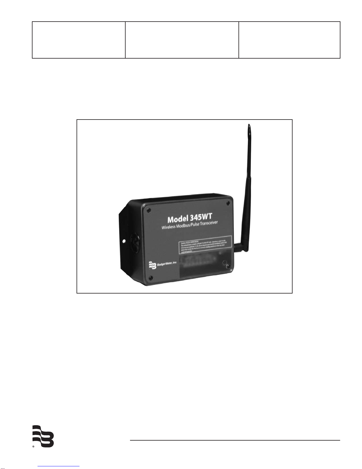
firmware your Badger®Data Industrial®Model 345WT has
installed, read the firmware version register with a Modbus
utility, or use the Advanced Configuration page in the Model
3700setup menu.  Firmwareupdateles maybeobtained
from Badger Meter Technical Support.
ThefirmwareupdateprocessrequiresanRS232serialportand
a windows computer to run the firmware update utility. Before
starting this process, verify your computer has a serial port
available. You may need to deactivate other software such as
the palm pilot utility or ups monitor software. USB connected
serial ports may be used, however these are not as fast or reli-
able as standard computer serial ports and may fail to upgrade
the firmware correctly.
To update the firmware, use the following procedure.
Step 1:InstallthePhilipsLPC2000softwareasprovidedby
Badger Meter.
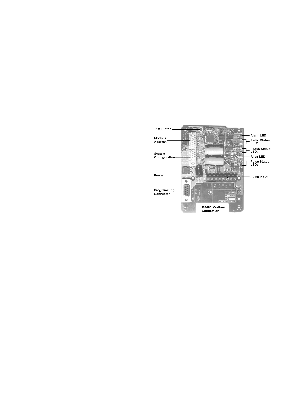
Step 2: Remove power from the Model 345WT. Attach the
Model 345WT to your computer with an RS232 serial
cable. The Model 345WT programming connector is
the 9 pin RS232 connector to the side of the power
jack.
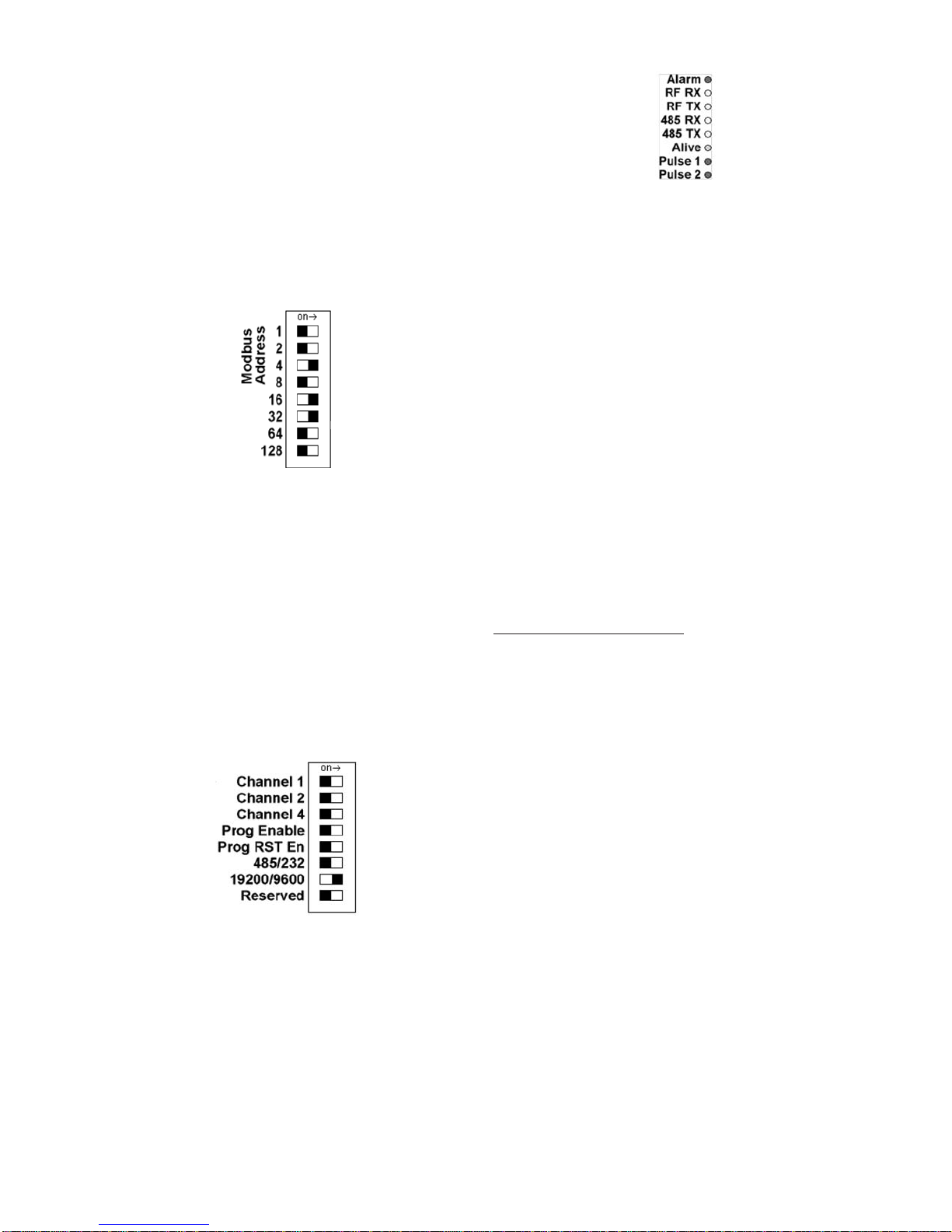
Step 3: Set the following dip switches:
Prog Enable = on
ProgRstEn = on
 485/232=on
Step 4: Power up the Model 345WT. The Green Alive LED
should light up and stay on solid.
Step 5:RuntheLPC2000FlashUtility.Thefollowingscreen
will be displayed.
Step 6: Set the following communications options:
COM1 or COM2 depending on your computer
serial port.
  Usebaudrate:38400orslower.
Check Use DTR/RTS for Reset
  XTALFreq[kHz]=20000
Step 7: Click the Read Device ID button. The PartID
and BootLoaderIDfieldswillbeshownifsuccessful.
Also, the Device dropdown menu should switch to
LPC2124.The bottomofthewindowwilldisplayRead
Part ID Successfully.
Step 8: Click the Filename...button. A dialog box will appear.
Locate and select the Model 345WT firmware image
le.Intheexampleabove,thisisnamedR9120_v1.13b.
hex.
Step 9: ClicktheUpload toFlash button.Thefirmwareupdate
willstart,andablueprogressbarwillbeshownacorss
the bottom of the screen.
Step 10: When the update is complete, disconnect power from
the Model 345WT. Remove the RS232 serial cable.
Turn off the three switches noted in step 3 above.
Prog Enable = OFF
Prog Rst En = OFF
  485/232=OFF
Step 11: Powerup theModel345WT.The newfirmwareshould
nowoperate. Toconfirmthenewfirmwareisinstalled,
use the Model 3700 device details page, click the
Configure button, and then the Advanced button.The
firmwareversionnumberwillbedisplayedonthelower
right side of the advanced details page.
Badger®and Data Industrial® are registered trademarks of Badger Meter Inc.

Other Badger Meter Transceiver manuals

Badger Meter Impeller ModHopper R9120-5 User manual

Badger Meter

Badger Meter Impeller ModHopper R9120-5 User manual

Badger Meter ORION SE User manual

Badger Meter

Badger Meter ORION SE User manual

Badger Meter ORION SE User manual

Badger Meter

Badger Meter ORION SE User manual

Popular Transceiver manuals by other brands

Altronix HubWay LD Series installation guide

Altronix

Altronix HubWay LD Series installation guide

Kenwood TH-75A instruction manual

Kenwood

Kenwood TH-75A instruction manual

Hope RF RFM12B quick start

Hope RF

Hope RF RFM12B quick start

NI PXIe-5840 Getting started guide

NI

NI PXIe-5840 Getting started guide

Standard Horizon HX751 Service manual

Standard Horizon

Standard Horizon HX751 Service manual

Technisonic Industries Limited TDFM-136B Quick reference guide

Technisonic Industries Limited

Technisonic Industries Limited TDFM-136B Quick reference guide

Kenwood TS-440S instruction manual

Kenwood

Kenwood TS-440S instruction manual

Comtech EF Data CSAT-5060 Installation and operation manual

Comtech EF Data

Comtech EF Data CSAT-5060 Installation and operation manual

Wideye Safari installation guide

Wideye

Wideye Safari installation guide

ON Semiconductor NCV7425EVB user manual

ON Semiconductor

ON Semiconductor NCV7425EVB user manual

Kenwood TH-25A Series instruction manual

Kenwood

Kenwood TH-25A Series instruction manual

Crow FW2 MERLIN PRO Installation and programming guide

Crow

Crow FW2 MERLIN PRO Installation and programming guide

Ranger RCI-69FFC4 user manual

Ranger

Ranger RCI-69FFC4 user manual

Mag One BPR 40 Service manual

Mag One

Mag One BPR 40 Service manual

Yaesu FT-480R instruction manual

Yaesu

Yaesu FT-480R instruction manual

ELECRAFT KX3-2M Installation and operating instruction manual

ELECRAFT

ELECRAFT KX3-2M Installation and operating instruction manual

KTI Networks KT-10T installation guide

KTI Networks

KTI Networks KT-10T installation guide

Keysight Technologies M9420A Getting started guide

Keysight Technologies

Keysight Technologies M9420A Getting started guide

manuals.online logo
manuals.online logoBrands
  • About & Mission
  • Contact us
  • Privacy Policy
  • Terms and Conditions

Copyright 2025 Manuals.Online. All Rights Reserved.