manuals.online logo
Brands
  1. Home
  2. •
  3. Brands
  4. •
  5. Baer
  6. •
  7. Control Unit
  8. •
  9. Baer M-Bus XC User manual

Baer M-Bus XC User manual

M-Bus Interface Module XC
User Manual
Page 1 from 6
E110003813092
Bär Industrie-Elektronik GmbH Rathsbergstr. 23 D-90411 Nürnberg Phone +49 911 970590 Fax +49 911 9705950
General
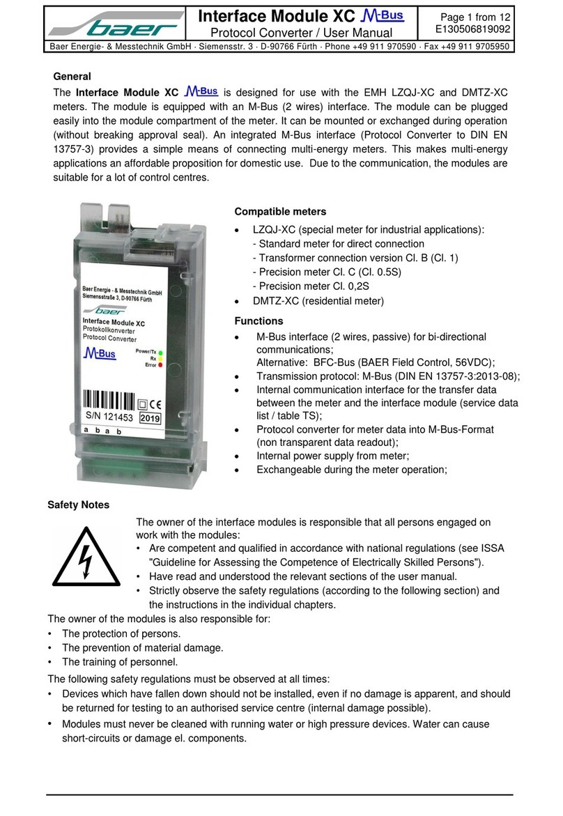
The M-Bus Interface Module XC is designed for use with the EMH LZQJ-XC and DMTZ-XC
meters. The module is equipped with a M-Bus (passive) interface (M-Bus level converter /
transparent).
The module can be plugged easily into the module compartment of the meter. It can be mounted
or exchanged during operation (without breaking approval seal). Due the transparent mode, the
modules are suitable for all common control centres.
Compatible meters
LZQJ-XC (special meter for industrial applications):
- Standard meter for direct connection
- Transformer connection version Cl. B (Cl. 1)
- Precision meter Cl. C (Cl. 0.5S)
- Precision meter Cl. 0,2S
DMTZ-XC (residential meter)
Functions
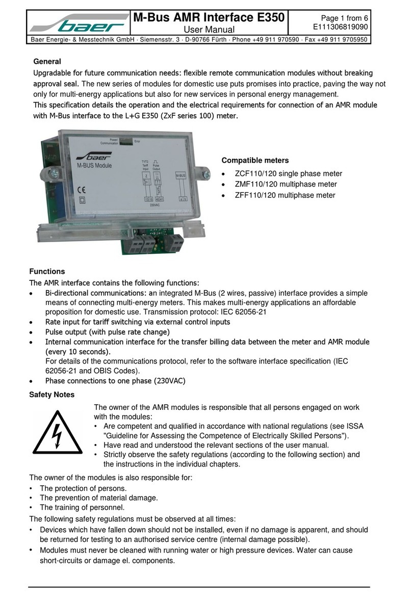
The AMR interface contains the following functions:
Bi-directional communications: an integrated M-Bus
(2 wires, passive) interface provides a simple
means of connecting multi-energy meters. This
makes multi-energy applications an affordable
proposition for domestic use.
Alternative: BFC-Bus (BAER Field Control, 56VDC)
Transmission protocol: IEC 62056-21 or DLMS
Internal communication interface for the transfer
billing data and load profiles between the meter and
AMR module.
For details of the communications protocol, refer to
the software interface specification (IEC 62056-21
and OBIS Codes).
Transparent data readout (without protocol
conversion).
Internal power supply from meter.
Exchangeable during the meter operation.
Safety Notes
The owner of the interface modules is responsible that all persons engaged on
work with the modules:
•Are competent and qualified in accordance with national regulations (see ISSA
"Guideline for Assessing the Competence of Electrically Skilled Persons").
•Have read and understood the relevant sections of the user manual.
•Strictly observe the safety regulations (according to the following section) and
the instructions in the individual chapters.
The owner of the modules is also responsible for:
•The protection of persons.
•The prevention of material damage.
•The training of personnel.
The following safety regulations must be observed at all times:
•Devices which have fallen down should not be installed, even if no damage is apparent, and should
be returned for testing to an authorised service centre (internal damage possible).
•Modules must never be cleaned with running water or high pressure devices. Water can cause
short-circuits or damage el. components.
Page 2 from 6
E110003813092
M-Bus Interface Module XC
User Manual
Bär Industrie-Elektronik GmbH Rathsbergstr. 23 D-90411 Nürnberg Phone +49 911 970590 Fax +49 911 9705950
Installation Hints
The installation must be done in a way, that even in the case of cable break no dangerous voltages
are applied to touchable parts of the module. Generally, meters are delivered with the communication
modules installed. The fitting of a meter with a communication module is, therefore, an exception and
can be necessary e.g. when a module needs to be replaced.
Strictly observe the safety regulations!
The interface module is exchangeable during the meter operation. Fit the interface module in the meter
as follows:
Installation of the interface module:
1. Check the interface module.
2. Remove the terminal cover [5].
3. Open the transparent cover [1].
4. Insert the interface module [3] carefully at the
place provided in the meter [2].
5. Push the module in to the internal contacts
6. Connect the cable.
7. Close the transparent cover [1].
8. Close the terminal cover [5].
Removing of the interface module:
9. Remove the terminal cover [5].
10. Open the transparent cover [1].
11. Disconnect the cable.
12. Remove the interface module.
13. Close the cover [1].
14. Close the terminal cover [5].
LED Displays
Two LED’s display the current operating status of the module and give information about the data transfer.
Tx: 

on: communication via M-Bus interface: transmit data
Rx: 

on: communication via M-Bus interface: receive data
M-Bus Interface Module XC
User Manual
Page 3 from 6
E110003813092
Bär Industrie-Elektronik GmbH Rathsbergstr. 23 D-90411 Nürnberg Phone +49 911 970590 Fax +49 911 9705950
Communication
The interface port is conforming to IEC 62056-21 with fixed baud rate. For setting the baud rate use
please the EMH COMBI-TOOL-Software: menu Meter Interfaces Electrical interface.
For reading data the meter-ID (device address) can be used (e.g. /?<meter-ID>!).
Explanations of massage contents (see IEC 62056-21):
Start character: / (forward oblique, code 2FHex)
End character: ! (exclamation mark, code 21Hex)
Completion character: CR (carriage return, code 0DHex) and LF (line feed, Code 0AHex); enter key
Example for communication path:
Sign-on sequence: /?! CR LF without meter-ID
or /?12345678! CR LF if the meter-ID := 12345678
Answer: /EMHzIdent CR LF z := baud rate identification
Sign-on acknowledgement: ACK 0z0 CR LF
Data readout (billing list): /EMH5\@\201LZQJL001VE
F.F(00000000)
0.0.0(12345678)
0.1.0(03)
0.1.2*03(0120216091536)
0.1.2*02(0120101000000)
0.1.2&01(0111209125955)
…
0.2.2(00000024)
0.9.1(0155843)
0.9.2(0120216)
1.2.1(0010.09*kW)
2.2.1(0000.00*kW)
…
!
Possible telegrams (for more information see please the meter manual):
Billing list: sign-on sequence: /?!
Table 1: sign-on sequence: /1!
Table 2: sign-on sequence: /2!
Table 3: sign-on sequence: /3!
Table 4 (service data): sign-on sequence: /4!
Load profile P.01
User profile P.02
Log book P.98
PTB log book P.99
User log book P.200
Option: DLMS protocole;
Page 4 from 6
E110003813092
M-Bus Interface Module XC
User Manual
Bär Industrie-Elektronik GmbH Rathsbergstr. 23 D-90411 Nürnberg Phone +49 911 970590 Fax +49 911 9705950
Technical data:
Housing:
Polycarbonate housing with terminals for using with EMH LZQJ-XC and
DMTZ-XC meters for residential and industrial applications
Degree of protection:
IP20 (according to IEC 60529)
Protection class:
2
Dimensions:
50mm x 105mm x 27mm (W x H x D)
Nominal voltage:
Internal power supply from LZQJ-XC or DMTZ-XC meter
M-Bus load
1,9mA
Installation:
exchangeable during the meter operation
Temperature range:
-25°C to +55°C (operational)
-40°C to +80°C (storage temperature)
Relative humanity:
0..95%, non-condensing
LED displays:
2 LED’s: 

(green) Tx: transmit data


(yellow) Rx: receive data
Interface:
M-Bus (2 wires, passive) according to EN 13757-2 (physical layer)
alternative: BFC-Bus (BAER Filed Control, 56VDC)
Baud rate:
300 to 9600 baud (fixed baud rate)
Data format:
IEC 62056-21: 7E1
DLMS: 8N1
Data readout:
Transparent data readout suitable for all common control centers
Note: it is a transparent M-Bus level converter without protocol
conversion
Transmission protocol:
IEC 62056-21 (conform to VDEW2+) with fixed baud rate (OBIS
Codes) or DLMS (option)
M-Bus Interface Module XC
User Manual
Page 5 from 6
E110003813092
Bär Industrie-Elektronik GmbH Rathsbergstr. 23 D-90411 Nürnberg Phone +49 911 970590 Fax +49 911 9705950
Dimensions
Page 6 from 6
E110003813092
M-Bus Interface Module XC
User Manual
Bär Industrie-Elektronik GmbH Rathsbergstr. 23 D-90411 Nürnberg Phone +49 911 970590 Fax +49 911 9705950
Subject to change without notice! Version 1.00
Terminal assignment
Terminal block:
Terminal
Description
a
M-Bus (passive) or BFC-Bus
b
M-Bus (passive) or BFC-Bus
Baer Industrie-Elektronik GmbH
Rathsbergstr. 23
D-90411 Nürnberg
Phone: +49 (0)911 970590
Fax: +49 (0)911 9705950
Internet: www.baer-gmbh.com

Other Baer Control Unit manuals

Baer Interface Module XC User manual

Baer

Baer Interface Module XC User manual

Baer M-Bus AMR Interface E350 User manual

Baer

Baer M-Bus AMR Interface E350 User manual

Popular Control Unit manuals by other brands

Moxa Technologies MiiNePort W1 Series user manual

Moxa Technologies

Moxa Technologies MiiNePort W1 Series user manual

Deditec COS Series Hardware description

Deditec

Deditec COS Series Hardware description

Siemens VAI60.15-15 Mounting instructions

Siemens

Siemens VAI60.15-15 Mounting instructions

SUPPO OSD v3.51 manual

SUPPO

SUPPO OSD v3.51 manual

Elkron IT700-WIFI quick start guide

Elkron

Elkron IT700-WIFI quick start guide

Keysight 34941A user guide

Keysight

Keysight 34941A user guide

Dualsky VR Pro Duo instruction manual

Dualsky

Dualsky VR Pro Duo instruction manual

Yoshitake GD-28S-NE product manual

Yoshitake

Yoshitake GD-28S-NE product manual

Cinterion MC75i Hardware interface description

Cinterion

Cinterion MC75i Hardware interface description

Sylvania BACKlight 2nd Generation BL02 installation guide

Sylvania

Sylvania BACKlight 2nd Generation BL02 installation guide

Siemens Desigo PXC4.E16 manual

Siemens

Siemens Desigo PXC4.E16 manual

Siemens SIMATIC ET 200SP manual

Siemens

Siemens SIMATIC ET 200SP manual

HIMA HIMax X-DI 32 05 instruction manual

HIMA

HIMA HIMax X-DI 32 05 instruction manual

Emerson PACSystems RX3i quick start guide

Emerson

Emerson PACSystems RX3i quick start guide

Viega Easytop 2275.10 Instructions for use

Viega

Viega Easytop 2275.10 Instructions for use

Helvest FleX GAW400 quick start guide

Helvest

Helvest FleX GAW400 quick start guide

Jonix VMC Use and maintenance manual

Jonix

Jonix VMC Use and maintenance manual

H3C PSR1600B-12A-B user manual

H3C

H3C PSR1600B-12A-B user manual

manuals.online logo
manuals.online logoBrands
  • About & Mission
  • Contact us
  • Privacy Policy
  • Terms and Conditions

Copyright 2025 Manuals.Online. All Rights Reserved.