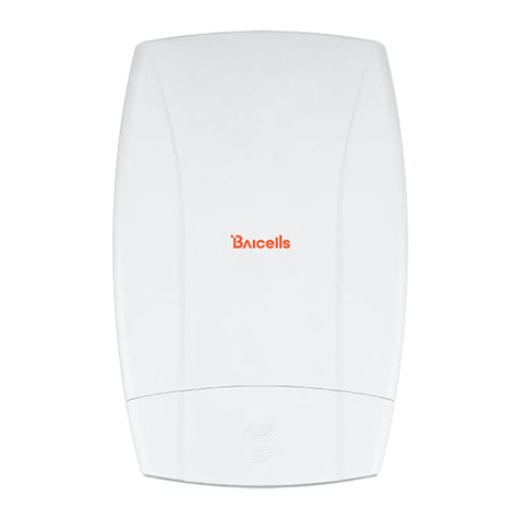
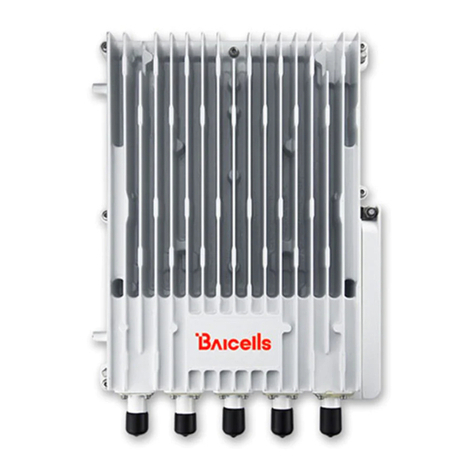
Baicells EP3011 User manual

SNAP PoE Router
Installation &
Configuration Guide
Model EP3011
May 2020
Version 1.3

ii
About This Document
This document is for operators who will be installing and configuring the Baicells Simple Network Access Point (SNAP)
Power over Ethernet (PoE) Router, model EP3011. This document version is based on the supported Baicells outdoor
customer premise equipment (CPE) software version BCE-BMI-1.2.0 (CAT4).
Related Documents
All technical specifications and documents are on the Baicells website under Resources > Documentation.
•Baicells SNAP PoE Router Data Sheet
•Baicells Atom OD0406 LG-HG User Manual
•Baicells Atom OD12H User Manual
Copyright Notice
Baicells Technologies, Inc., copyrights the information in this document. No part of this document may be reproduced
in any form or means without the prior written consent of Baicells Technologies, Inc. The Baicells logo is a proprietary
trademark of Baicells Technologies, Inc. Other trademarks mentioned in this document belong to their owners.
Revision Record
Date
Version
Description
SMEs/Contributors
Author/Editor
06-May-2020
V1.3
Removed “+” in references
to SNAP PoE Router
Tang Houcheng
Kathy Clark
22-Apr-2020
21-Apr-2020
v1.2
v1.1
SME comment updates
Draft-2
Tang Houcheng, Jie Lewis,
Nitisha Potti
Sharon Redfoot
16-Apr-2020
v1.0
Draft
-
Tang Houcheng
Support Resources
•Documentation - Baicells product data sheets, this document, and other technical manuals may be found at
Baicells > Resources > Documentation.
•Support - Open a support ticket, process an RMA, and the Support Forum are at Baicells > Support.
Contact Us
Baicells Technologies Co., Ltd.
Baicells Technologies North America, Inc.
China
North America
Address:
3F, Bldg. A, No. 1 Kai Tuo Rd, Haidian
Dist, Beijing, China
555 Republic Dr., #200, Plano, TX 75074, USA
Phone:
+86-10-62607100
+1-888-502-5585
Email:
Website:
www.Baicells.com
https://na.Baicells.com

iii
Table of Contents
1. Introduction.................................................................................................................................1
1.1 DESCRIPTION....................................................................................................................................................1
1.2 SUPPORTED ODU CPES.....................................................................................................................................1
1.3 FEATURES ........................................................................................................................................................2
2. Installation ...................................................................................................................................2
2.1 INTERFACES......................................................................................................................................................2
2.2 LEDS..............................................................................................................................................................3
2.3 MATERIALS ......................................................................................................................................................3
2.4 PROCEDURE .....................................................................................................................................................4
3. Configuration ...............................................................................................................................5
3.1 COMPUTER REQUIREMENTS.................................................................................................................................5
3.2 CPE SOFTWARE ................................................................................................................................................5
3.3 LOGIN.............................................................................................................................................................5
3.4 STATUS MENU ..................................................................................................................................................5
3.5 NETWORK MENU ..............................................................................................................................................9
3.6 LTE MENU.....................................................................................................................................................17
3.7 SECURITY MENU .............................................................................................................................................20
3.8 VPN MENU...................................................................................................................................................25
3.9 SYSTEM MENU ...............................................................................................................................................31
3.10 REBOOT ........................................................................................................................................................38
3.11 LOGOUT ........................................................................................................................................................38
Appendix: Regulatory Compliance ...............................................................................................................................39
List of Figures
FIGURE 1: SNAP POE ROUTER .............................................................................................................................................1
FIGURE 2: INTERFACES.........................................................................................................................................................2
FIGURE 3: EQUIPMENT SETUP ...............................................................................................................................................2
FIGURE 4: LEDS.................................................................................................................................................................3
FIGURE 5: LOGIN................................................................................................................................................................5
FIGURE 6: STATUS...............................................................................................................................................................6
FIGURE 7: ODU CPE SIGNAL INTENSITY (STRENGTH) - ATOM OD04L EXAMPLE ..............................................................................8
FIGURE 8: ROUTES..............................................................................................................................................................9
FIGURE 9: LAN..................................................................................................................................................................9
FIGURE 10: DHCP ...........................................................................................................................................................10

iv
FIGURE 11: BUNDLED ADDRESS LIST.....................................................................................................................................10
FIGURE 12: WAN ............................................................................................................................................................10
FIGURE 13: WLAN (1 OF 2)...............................................................................................................................................11
FIGURE 14: WLAN (2 OF 2)...............................................................................................................................................12
FIGURE 15: DEVICE CONFIGURATION (2.4 GHZ SSID)..............................................................................................................12
FIGURE 16: INTERFACE CONFIGURATION (2.4 GHZ SSID) .........................................................................................................12
FIGURE 17: DEVICE CONFIGURATION (5 GHZ SSID).................................................................................................................13
FIGURE 18: INTERFACE CONFIGURATION (5 GHZ SSID) ............................................................................................................14
FIGURE 19: WIFIDOG BASIC SETTINGS..................................................................................................................................15
FIGURE 20: WHITELIST ......................................................................................................................................................15
FIGURE 21: ADVANCED......................................................................................................................................................15
FIGURE 22: STATIC ROUTES ................................................................................................................................................16
FIGURE 23: DMZ EXAMPLES ..............................................................................................................................................16
FIGURE 24: DMZ.............................................................................................................................................................17
FIGURE 25: CONNECTION MODE .........................................................................................................................................17
FIGURE 26: SCAN MODE ...................................................................................................................................................17
FIGURE 27: DEDICATED EARFCN ........................................................................................................................................18
FIGURE 28: CELL LOCK ......................................................................................................................................................18
FIGURE 29: PCI LOCK .......................................................................................................................................................19
FIGURE 30: APN MANAGEMENT.........................................................................................................................................19
FIGURE 31: PIN MANAGEMENT ..........................................................................................................................................20
FIGURE 32: SIM LOCK ......................................................................................................................................................20
FIGURE 33: FIREWALL .......................................................................................................................................................20
FIGURE 34: MAC FILTER....................................................................................................................................................21
FIGURE 35: IP FILTER ........................................................................................................................................................21
FIGURE 36: URL FILTER .....................................................................................................................................................22
FIGURE 37: PORT FORWARDING ..........................................................................................................................................22
FIGURE 38: PORT TRIGGERING ............................................................................................................................................23
FIGURE 39: ALG..............................................................................................................................................................24
FIGURE 40: UPNP............................................................................................................................................................24
FIGURE 41: ATTACK PROTECTION.........................................................................................................................................25
FIGURE 42: VPN MENU ....................................................................................................................................................25
FIGURE 43: IPSEC ............................................................................................................................................................26
FIGURE 44: IPSEC ............................................................................................................................................................26
FIGURE 45: L2TP.............................................................................................................................................................27
FIGURE 46: PPTP ............................................................................................................................................................28
FIGURE 47: GRE..............................................................................................................................................................29
FIGURE 48: OPENVPN......................................................................................................................................................30
FIGURE 49: SERVER ..........................................................................................................................................................30
FIGURE 50: CLIENT ...........................................................................................................................................................30
FIGURE 51: NTP..............................................................................................................................................................31
FIGURE 52: ACCOUNT .......................................................................................................................................................31
FIGURE 53: WEB SETTING .................................................................................................................................................32
FIGURE 54: FTP AUTO UPGRADE.........................................................................................................................................32
FIGURE 55: TR-069 .........................................................................................................................................................33
FIGURE 56: SNMP...........................................................................................................................................................34
FIGURE 57: RESTORE/UPDATE.............................................................................................................................................35

v
FIGURE 58: PING WATCHDOG.............................................................................................................................................36
FIGURE 59: DIAGNOSIS......................................................................................................................................................36
FIGURE 60: PING .............................................................................................................................................................37
FIGURE 61: TRACEROUTE ...................................................................................................................................................38
FIGURE 62: REBOOT .........................................................................................................................................................38
FIGURE 63: LOGOUT .........................................................................................................................................................38
List of Tables
TABLE 1: INTERFACES ..........................................................................................................................................................2
TABLE 2: LEDS..................................................................................................................................................................3
TABLE 3: MATERIALS...........................................................................................................................................................3
TABLE 4: INSTALLATION PROCEDURE .......................................................................................................................................4
TABLE 5: COMPUTER REQUIREMENTS .....................................................................................................................................5
TABLE 6: STATUS ................................................................................................................................................................7
TABLE 7: SSID (2.4 GHZ) CONFIGURATION ...........................................................................................................................12
TABLE 8: SSID (5 GHZ) CONFIGURATION ..............................................................................................................................14
TABLE 9: IP FILTER............................................................................................................................................................21
TABLE 10: PORT FORWARDING............................................................................................................................................23
TABLE 11: IPSEC..............................................................................................................................................................26
TABLE 12: L2TP ..............................................................................................................................................................28
TABLE 13: PPTP..............................................................................................................................................................28
TABLE 14: GRE ...............................................................................................................................................................29
TABLE 17: WEB SETTING ..................................................................................................................................................32
TABLE 18: TR-069...........................................................................................................................................................33
TABLE 19: SNMP ............................................................................................................................................................34

1
1. Introduction
1.1 Description
The Baicells Simple Network Access Point (SNAP) Power over Ethernet (PoE) Router, model EP3011, is an on-
premise Wi-Fi access point (Figure 1). The router provides comprehensive routing capabilities to multiple
users accessing the Internet through a Baicells outdoor unit (ODU) Customer Premise Equipment (CPE) device.
The router provides PoE power to the ODU through the local area network (LAN) connection, thus eliminating
the need for a separate power connection and adaptor for the CPE.
Wi-Fi signals from users' mobile phones, laptops, and tablets pass through the SNAP router and are
forwarded to the ODU CPE where the Wi-Fi signals are changed to Long-Term Evolution (LTE) signals and sent
to an eNodeB (eNB), or base station, and then on to the high-speed LTE network. The SNAP router supports
2.4 GHz and 5 GHz Wi-Fi and may be used with the Baicells Outdoor Low-Gain or Outdoor High-Gain CPEs.
Figure 1: SNAP PoE Router
1.2 Supported ODU CPEs
SNAP PoE Router model EP3011 can power on passive PoE devices, and by default is configured in LTE Indoor
Unit (IDU) mode. In LTE IDU mode, the router connects to a Baicells outdoor CPE and works in Bridge mode.
The WAN port is used as a trunk port and cannot connect to other devices such as non-supported, third-party
CPEs and optical or ADSL modems. The following Baicells ODU CPEs are supported:
•Atom OD04H - Outdoor CAT4 high-gain CPE, model EG7035E
•Atom OD04L - Outdoor CAT4 low-gain CPE, model EG7035L
•Atom OD06H - Outdoor CAT6/7 high-gain CPE, model EG7010A
•Atom OD06L - Outdoor CAT6/7 low-gain CPE, model EG7010C
•Atom OD12H - Outdoor CAT12 high-gain CPE, model EG8050A (future availability)
These Baicells outdoor CPEs run on software that is specific for use with the SNAP router. Check the Baicells
website under Resources > Firmware to download the software, or contact Baicells support for assistance.

2
1.3 Features
NOTE: Features may vary based on model or region.
•1000 Mbps WAN with PoE output
•1000 Mbps Ethernet LAN port
•Standard IEEE 802.11b/g/n/ac Wi-Fi operating in dual-band 2.4 GHz and 5 GHz mode
•Local and remote CPE management
•TR-069 network management protocol supported
•User-friendly LED status indicators
For the technical specifications, please refer to the data sheet on the Baicells website.
2. Installation
2.1 Interfaces
The interfaces on the back of the PoE router equipment include a reset button, 2 LAN ports, a WAN port, a
power adapter connector, and a power on/off button (Figure 2). Each interface is described in Table 1.
Figure 2: Interfaces
Table 1: Interfaces
Interface
Description
RST
Reset button - press at least 10 seconds to reset the unit to its factory settings
LAN2/LAN1
2 RJ-45, LAN 10/100/1000 auto-sensing, auto-MDX ports
WAN
1 RJ-45, WAN 10/100/1000 auto-sensing, auto-MDX, 24V 0.5A passive Power Sourcing
Equipment (PSE) port
POWER
24VDC, 1A
A preview of the equipment setup is shown in Figure 3.
Figure 3: Equipment Setup

3
2.2 LEDs
On the front of the router are 4 LED indicators for signal level, Internet connection status, Wi-Fi status, and
power (Figure 4). Refer to Table 2 for a description of each LED.
Figure 4: LEDs
Table 2: LEDs
LED
Status
Description
Signal
Steady ON
The more "bars" lit up, the stronger the LTE signal
OFF
No signal or weak signal
Blinking
1 "bar" blinking means the unit is scanning the LTE network
2 "bars" blinking means the unit is attaching to the LTE network
3 "bars" blinking means the unit is attached to the LTE network
Internet
Steady ON
The unit is connected to the LTE network
OFF
The unit is not connected to the LTE network
Blinking
The unit is trying to connect to the LTE network
WiFi
Steady ON
Wi-Fi is enabled and working
OFF
Wi-Fi is disabled, not working
Blinking
Wi-Fi is starting up
Power
Steady ON
The unit is powered on
OFF
There is no power supply to the unit
2.3 Materials
Before installing the router, prepare the materials listed in Table 3.
Table 3: Materials
Item
Description
Ethernet cable
Outdoor Shield CAT5E, shorter than 330 feet. Connects the CPE PoE port and the router
WAN port.
Ground wire
16mm² yellow-green wire
Supported LTE ODU
CPE device
Baicells CPE model EG7035E, EG7035L, EG7010A, EG7010C, or EG8050A with
corresponding firmware

4
2.4 Procedure
To explain the installation, the procedure in Table 4 uses a Baicells Atom OD04L Outdoor Low-Gain CPE as the
example. Refer to the CPE user manual on the Baicells website to complete some steps as indicated.
Table 4: Installation Procedure
1. With the CPE powered OFF, loosen the screws on the
waterproof cover and lift to access the interfaces.
2. Insert the SIM card into the SIM slot.
Attention: Never power on the CPE while installing or
uninstalling the SIM card. Doing so could damage the
card and the unit.
3. Using the Ethernet cable, connect the CPE PoE port
and the router WAN port.
Caution: Do not connect unsupported devices to
the router WAN port, as it may cause damage.
Per the associated steps in the CPE user manual
installation procedure:
4. Prepare the ground wire and connect one end of it to
the CPE ground terminal and the other end to a
reliable grounding point (earth).
5. Close the CPE's waterproof cover, and tighten the
screws.
6. Mount the CPE at its outdoor location, assuring proper
alignment to the nearest eNB tower.
7. Power the CPE ON, and check the satus of the LEDs to
ensure it is operating as expected.
8. Connect the router's power adapter to the power
connector on the back of the unit, and the other
end to a power outlet.
9. Turn power to the router ON.
10. Check the LED indicators to verify normal
operating status per Table 2 in section 2.2 of this
guide.
NOTE: If either the CPE or the router is not running the correct firmware, the router's LTE signal LED
will be OFF. Check for the latest firmware on the Baicells website, or contact Baicells support.
The setup is complete and ready to work. To configure features using the CPE GUI, go to the next section.

5
3. Configuration
3.1 Computer Requirements
The computer you use to connect with the CPE GUI must meet the requirements shown in Table 5.
Table 5: Computer Requirements
Item
Description
CPU
Pentium 500 MHz or higher
Memory
128 MB RAM or higher
Hard Disk
50MB available space
Operating System
Microsoft : Windows XP, Windows Vista, Windows 7 or higher
Mac: MacOSX 10.5 or higher
Screen Resolution
1024 x 768 pixels or higher
Browser
Google Chrome 9 or later
Internet Explorer 7.0 or later
Mozilla Firefox 3.6 or later
Safari 5 or later
3.2 CPE Software
The supported outdoor Baicells CPE must run the software designed for use with a SNAP router. At this time,
the software version for CAT4 is BCE-BMI-1.2.0. If the outdoor CPE is not running this version, please
download it from the Baicells website > Resources > Firmware or contact Baicells support.
3.3 Login
The CPE comes preloaded with a GUI to configure the device. With the CPE turned on and connected to the
router, access the GUI login page by opening a Web browser and entering http://192.168.150.1.
Figure 5: Login
Initially, use the default Username = admin/Password = admin (Figure 5). Once
you are in the GUI, you will want to change the password; please refer to
section 3.9.2 Account.
3.4 Status Menu
3.4.1 Overview
After logging in, the GUI opens to the Status > Overview page (Figure 6). This page is a dashboard of key
information regarding the CPE. The top row, Current State, shows the network connection status, signal
intensity, LAN link status, and the number of smart devices (cell phones, pc's, laptops) connected to the
Internet through the CPE.

6
The Device Info pane displays the product name, software version, serial number, etc. The LTE Status pane
shows important operational information, such as the CPE's SIM card status and its IMSI and IMEI numbers,
wireless frequency being used, eNB connection status, and current signal strength and quality.
Under Throughput Statistics you will see downlink (DL) and uplink (UL) data rates for current throughput
(kbps), average rates, peak rates, and total throughput. The data is measured during a 3-second interval every
5 minutes. The APN Status pane displays any gateway connections. The bottom pane, Devices List, will show
details about all smart devices currently connected through the CPE. Refer to Table 6 for a description of the
Status fields.
Figure 6: Status

7
Table 6: Status
Field Name
Description
Connection State
Connection status between the CPE and the network –either Checking SIM, Scanning,
Registering, Acquiring IP, Connected, or Disconnected
Signal Intensity
Indicates the strength of the signal between this CPE and the serving eNB, either
excellent, good, general, bad, or severe. The ODU CPE hardware typically displays 1 to 5
LEDs to indicate this level (Figure 7).
Lan State
Indicates the local area network connection status
Devices Connected
The number of smart devices connected to the Internet through this CPE via a LAN or
Wireless LAN (WLAN)/Wi-Fi connection
Device Info
Product Name
LTE-ROUTER indicates the CPE is operating as a router
Product Model
ODU CPE model number
Hardware Version
ODU CPE hardware version
Module Name
Type of LTE module in the CPE
CloudKey
Network operator's unique identity from Baicells
Software Version
ODU CPE operating software version
Software Build Time
Date and time the software was built
Module Version
ODU CPE LTE module firmware version
NickName
ODU CPE name configured by the network operator
LTE Status
USIM Status
The Universal Subscriber Identity Module, or SIM, card status is either available or not
ready in the ODU CPE
IMSI
The unique International Mobile Subscriber Identity (IMSI) number associated with the
SIM card in the subscriber's ODU CPE. The IMSI must be identifiable by the operator's
LTE network in order to access it.
LTE Mode
The LTE network operates with either Time Division Duplexing (TDD) or Frequency
Division Duplexing (FDD)
IMEI
International Mobile Equipment Identity is like a serial number for the SIM card
PLMN
The Public Land Mobile Number (PLMN), or operator network ID, to which the CPE is
connected
Bandwidth
The range of frequencies within the band the CPE may use for wireless communications
with an eNB, expressed in MHz
Cell ID
The operator's cell site ID to which the CPE is connected. A cell site may comprise more
than one eNB. Each eNB is given a PCI to identify it.
RSRQ
Reference Signal Receiving Quality indicates the quality of the wireless signal
PCI
The Physical Cell Identifier (PCI) unique to each eNB. PCI indicates to which eNB the
ODU CPE is connected. An operator can have multiple eNBs serving the same cell.
EARFCN
The E-UTRA Absolute Radio Frequency Channel Number (band and frequency) within
which the CPE operates
DL Frequency
The frequency, in MHz, being used in the downlink (eNB to CPE). In LTE, the carrier
frequency in the uplink and downlink is designated by the EARFCN, which identifies the
LTE band and carrier frequency.
UL Frequency
The frequency, in MHz, that the CPE is using in the uplink (CPE to eNB). In LTE, the
carrier frequency in the uplink and downlink is designated by the EARFCN, which
identifies the LTE band and carrier frequency.

8
DL MCS
Downlink Modulation and Coding Scheme - an indication of channel conditions
determining throughput in the downlink
UL MCS
Uplink Modulation and Coding Scheme - an indication of channel conditions
determining throughput in the uplink
SINR1 and SINR2
The Signal-to-Interference-plus-Noise Ratio reflects the signal strength of the signal
received from the two antennas in the eNB, expressed in decibels (dB)
NOTE: Additional SINR values are reported when a transmitting device is using more
than two antennas.
RSRP1 and RSRP2
The Reference Symbol Received Power is an indication of the average power of the LTE
reference signals over the entire bandwidth. RSRP is reported for each transmit
antenna. These signals must be at a high enough level for the CPE to attach to an eNB.
Throughput Statistics
DL
The current downlink data throughput rate, in Kbps
UL
The current uplink data throughput rate, in Kbps
Average
The average DL and UL data throughput rates, in Kbps, for this CPE in the last 3 minutes
Peak
The peak DL and UL data throughput rates, in Kbps, for this CPE in the last 3 minutes
Sum
The total (sum) DL and UL data throughput rates, in Kbps
APN Status
APN Number
Access Point Name (gateway) connection to other network devices. At least one APN
must be configured to establish the TR-069 connection to the CloudCore or other NMS
Enable
Indicates if the APN is enabled or disabled
MAC Address
MAC address of the APN gateway
Connection Type
Type of network connection
IP Address
IPv4, IPv6, or IPv4v6 address of the APN gateway
DNS server
Domain Name Server IP address
LAN Status
MAC Address
MAC address of the LAN device, e.g., router, to which the CPE is connected
IP Address
The IP address of the LAN device
Netmask
The subnet mask of the LAN device
Devices List
Index
Numerical ID assigned to each smart device connected through the ODU CPE
Device Name
The name of each smart device connected through the CPE
MAC Address
The MAC address of each smart device connected through the CPE
IP Address
The IP address of each device connected through the CPE
Lease Time
Amount of time a smart device’s IP address has been leased
Type
Type of smart device connection
Figure 7: ODU CPE Signal Intensity (Strength) - Atom OD04L Example

9
3.4.2 Routes
The Overview > Routes table lists all of the configured routing rules, including Allocation and Retention Policy
(ARP) tables and active IPv4/IPv6 routes (Figure 8). For each item in the list, the IP address, MAC address,
and interface type are displayed.
Figure 8: Routes
3.5 Network Menu
3.5.1 LAN Settings
Enter the Network > LAN host IP address, subnet mask, and the Maximum Transmission Unit (MTU) size, in
bytes (Figure 9). The range is 1000-2000 bytes. The default is 1500 bytes.
Figure 9: LAN
You can enable or disable the DHCP server (Figure 10). If enabled, enter the start and end IP addresses, and
the lease time for IP address use - from 10 minutes to 720 hours. Optionally, you can enter one or two DNS
server IP addresses, and one to three option 138 connection IP addresses for connecting to a Control and
Provisioning of Wireless Access Points (CAPWAP) server. When using option 138, the device will connect with
the server's LAN port and get an Access Controller (AC) IP address.

10
Figure 10: DHCP
The Bundled Address List may be used to bind an IP address to a specific MAC address (Figure 11). In the
bottom half of the pane, enter the IP address and the MAC address, and click on ADD. The IP address must
be within the range of DHCP addresses. Any configured bindings will appear at the top of the window.
Figure 11: Bundled Address List
3.5.2 WAN Settings
Since EP3011 is an IDU device, set the CPE WAN interface to LTE (Figure 12). The types of Network Modes
supported are Network Address Translation (NAT), Bridge, and Tunnel. NAT is the default mode and allows
multiple hosts on a private network to access the Internet using a single public IP address. Selecting Bridge
mode disables NAT and allows the CPE to function as a DHCP server without IP address conflict. If a DNS
server is configured (section 3.5.1), the CPE will parse the IP address from the DNS.
Figure 12: WAN

11
3.5.3 WLAN Settings
Referring to You can enable/disable an SSID from this page.
Figure 13, this window displays the Wireless LAN (WLAN) status, including the:
•Channel being used in which band, e.g., 2.4 GHz or 5 GHz
•Service Set Identifiers (SSIDs) enabled and disabled.
−When you set up a Small Office or Home Office (SOHO) wireless network, you give it a name
to distinguish it from other WLANs in your neighborhood whose wireless signals you are
able to receive on your device(s).
−Some SOHO WLANs have more than one SSID, e.g., one for 2.4 GHz and one for 5 GHz. Why?
Since not all end-user devices support 5 GHz, using the 5 GHz SSID might be less congested
and provide better service.
−SSIDs also provide a way to segment the WLAN for users with different security and VLAN
configurations.
−SNAP PoE Router model EP3011 supports up to 8 SSIDs, 4 for 2.4 GHz and 4 for 5.8 GHz.
•Mode - Master or Client, where Master changes the device's channel to match its channel
•Basic Service Set Identifiers (BSSID) - the MAC addresses of Wireless Access Points (WAP)
•Encryption method - security protocol being used
You can enable/disable an SSID from this page.
Figure 13: WLAN (1 of 2)
At the bottom of the WLAN window is a list of any devices associated with each SSID (
Figure 14). The information includes the MAC address, IP address, signal strength (dBm), and current data
rate. The data rate includes the speed (Mbps), the Modulation and Coding Scheme (MCS) value - an indication
of signal quality, and the channel bandwidth (MHz).

12
Figure 14: WLAN (2 of 2)
Every SSID can be configured independently. The example in Figure 15 and Figure 16 is for an SSID in the 2.4
GHz range. Refer to Table 7 for a description of each field.
Figure 15: Device Configuration (2.4 GHz SSID)
Figure 16: Interface Configuration (2.4 GHz SSID)
Table 7: SSID (2.4 GHz) Configuration
Item
Value
Description
Network Mode
802.11b/g
802.11b
802.11g
802.11g/n
802.11b/g/n
Wi-Fi mode selection
Channel
Channels 1~14 and auto
Wi-Fi frequency band
Bandwidth
20 MHz
40 MHz
Default: 40 MHz
Country Code
US
Default: None

13
JP
FR
TW
IE
HK
None
Support Channel
CH1~11
CH1~13
CH10~11
CH10~13
CH13
CH1~14
CH3~9
CH5~13
Supported channels. Default: CH1~14
ESSID
Alpha-numeric name
Extended Service Set Identifier which is a name
given to the WAP representing all SSIDs in the
WLAN
Mode
Access Point
EP3011 supports Access Point mode
WMM Mode
Enable/Disable
Wi-Fi MultiMedia defines the quality of service
(QoS) in the Wi-Fi network
Encryption
No Encryption
WEP Open System
WEP Shared Key
WPA-PSK
WPA2-PSK
WPA-PSK/WPA2-PSK Mixed Mode
WPA-EAP
WPA2-EAP
WPA-EAP/WPA2-EAP Mixed Mode
802.1x
IP security method. Different encryption
methods represent different security protocols
used for authentication. Depending on which
method is selected, additional fields will display.
For a 5 GHz SSID, the configuration varies slightly, as shown in Figure 17 and Figure 18. The fields are
described in Table 8.
Figure 17: Device Configuration (5 GHz SSID)

14
Figure 18: Interface Configuration (5 GHz SSID)
Table 8: SSID (5 GHz) Configuration
Item
Value
Description
Network Mode
802.11a, 802.11a/n, or 802.11a/n/ac
Wi-Fi mode selection
Channel
Channels 36~165 and auto
Wi-Fi frequency band
Bandwidth
20 MHz, 40 MHz, or 80 MHz
Default: 40 MHz
Country Code
US
JP
FR
TW
IE
HK
None
Default: None
Support Channel
CH36~64, CH 149~165
CH100~140
CH52~64, CH149~161
…
Supported channels. Default: CH36~64,
CH100~140, CH149~165
ESSID
Alpha-numeric name
Extended Service Set Identifier which is a
name given to the WAP representing all
SSIDs in the WLAN
Mode
Access Point
EP3011 supports Access Point mode
WMM Mode
Enable/Disable
Wi-Fi MultiMedia defines the quality of
service (QoS) in the Wi-Fi network
Encryption
No Encryption
WEP Open System
WEP Shared Key
WPA-PSK
WPA2-PSK
WPA-PSK/WPA2-PSK Mixed Mode
WPA-EAP
WPA2-EAP
WPA-EAP/WPA2-EAP Mixed Mode
802.1x
IP security method. Different encryption
methods represent different security
protocols used for authentication. Depending
on which method is selected, additional
fields will display.

15
3.5.4 WiFidog
WiFidog is a feature that may be used to build wireless hotspots for guest users. The feature requires a
connection to a remote authentication server. When Wifidog is enabled, guest Wi-Fi devices must be
authenticated through the remote authentication server. To enable WiFidog, in the Basic Settings tab click
on the check box next to Enable (Figure 19). Enter the AP code generated by the authentication server and
the server's IP address.
Figure 19: WiFidog Basic Settings
If you wish to limit which URLs guests can access, you can create a URL whitelist in the Whitelist tab (Figure
20). Enter the URLs, separated by commas, that guests will be allowed to access. For the free certification
equipment field, enter the hotspot users' device MAC address(es). Use a comma to separate each one.
Figure 20: Whitelist
The Advanced Settings tab is used to configure the authentication server (Figure 21). Enter the server's
gateway port number; HTTP port number; authentication server path; interval for how often the server will
check the device status, in seconds; and client/device timeout period, where the client will be disconnected
after no activity per this time period (minutes).
Figure 21: Advanced
Table of contents
Other Baicells Network Router manuals
Popular Network Router manuals by other brands

System Level Solutions
System Level Solutions NEEK Board Support Package uClinux user guide

TP-Link
TP-Link Archer C900 user guide

D-Link
D-Link DES-1210-52/ME Cli reference guide

Upvel
Upvel UR-326N4G user manual

Robustel
Robustel R2000 Ent Installation and configuration quick guide

Edimax
Edimax AR-7064+ Specifications