Baileigh Hare&Forbes MSS-14H User manual

OPERATOR’S MANUAL
METAL FORMING SHRINKER STRETCHER
MODEL: MSS-14H (B8860)
© 2019 Baileigh Industrial Holdings LLC
REPRODUCTION OF THIS MANUAL IN ANY FORM WITHOUT WRITTEN APPROVAL OF BAILEIGH INDUSTRIAL
HOLDINGS LLC IS PROHIBITED. Baileigh Industrial Holdings LLC, Inc. does not assume and hereby disclaims any
liability for any damage or loss caused by an omission or error in this Operator’s Manual, resulting from accident,
negligence, or other occurrence.
Rev. 07/2019

Table of Contents
INTRODUCTION............................................................................................................. 1
GENERAL NOTES.......................................................................................................... 1
SAFETY INSTRUCTIONS .............................................................................................. 2
SAFETY PRECAUTIONS ............................................................................................... 4
Dear Valued Customer:................................................................................................... 4
TECHNICAL SPECIFICATIONS..................................................................................... 6
UNPACKING AND CHECKING CONTENTS.................................................................. 6
Cleaning ...................................................................................................................... 7
TRANSPORTING AND LIFTING .................................................................................... 7
INSTALLATION............................................................................................................... 8
Anchoring the Machine................................................................................................ 9
GETTING TO KNOW YOUR MACHINE ....................................................................... 10
ASSEMBLY AND SET UP ............................................................................................ 11
Tooling Installation:.................................................................................................... 11
JAWS ............................................................................................................................ 14
ELECTRICAL................................................................................................................ 15
OPERATION................................................................................................................. 17
MATERIAL SELECTION............................................................................................... 18
LUBRICATION AND MAINTENANCE .......................................................................... 19
Hydraulic Oil .............................................................................................................. 19
Oil Disposal ............................................................................................................... 19
PARTS DIAGRAM ........................................................................................................ 20
Parts List ................................................................................................................... 24
Tooling Block Parts Diagram......................................................................................... 26
Tooling Block Parts List ............................................................................................. 26
ELECTRICAL SCHEMATIC.......................................................................................... 27

1
1
INTRODUCTION
The quality and reliability of the components assembled on a Baileigh Industrial Holdings LLC
machine guarantee near perfect functioning, free from problems, even under the most demanding
working conditions. However, if a situation arises, refer to the manual first. If a solution cannot be
found, contact the distributor where you purchased our product. Make sure you have the serial
number and production year of the machine (stamped on the nameplate). For replacement parts
refer to the assembly numbers on the parts list drawings.
Our technical staff will do their best to help you get your machine back in working order.
In this manual you will find: (when applicable)
•Safety procedures
•Correct installation guidelines
•Description of the functional parts of the machine
•Capacity charts
•Setup and start-up instructions
•Machine operation
•Scheduled maintenance
•Parts lists
GENERAL NOTES
After receiving your equipment remove the protective container. Do a complete visual
inspection, and if damage is noted, photograph it for insurance claims and contact your
carrier at once, requesting inspection. Temporarily suspend installation.
Take necessary precautions while loading / unloading or moving the machine to avoid any
injuries.
Your machine is designed and manufactured to work smoothly and efficiently. Following proper
maintenance instructions will help ensure this. Try and use original spare parts, whenever
possible, and most importantly; DO NOT overload the machine or make any modifications.
Note: This symbol refers to useful information throughout the manual.

2
2
SAFETY INSTRUCTIONS
LEARN TO RECOGNIZE SAFETY INFORMATION
This is the safety alert symbol. When you see this symbol
on your machine or in this manual, BE ALERT TO THE
POTENTIAL FOR PERSONAL INJURY!
Follow recommended precautions and safe operating practices.
UNDERSTAND SIGNAL WORDS
A signal word – DANGER,WARNING,or CAUTION – is used with the safety alert symbol.
NOTICE, which is not related to personal injury, is used without a symbol.
DANGER: Indicates a hazardous situation which, if not
avoided, will result in death or serious injury.
WARNING: Indicates a hazardous situation which, if not
avoided, could result in death or serious injury.
CAUTION: Indicates a hazardous situation which, if not
avoided, could result in minor or moderate injury.
NOTICE: Indicates a situation which, if not avoided, could
result in property damage.
IMPORTANT
PLEASE READ THIS OPERATORS MANUAL CAREFULLY
It contains important safety information, instructions, and necessary operating procedures.
The continual observance of these procedures will help increase your production and
extend the life of the equipment.
DANGER
WARNING
CAUTION
NOTICE

3
3
SAVE THESE INSTRUCTIONS.
Refer to them often and use them to instruct others.
PROTECT EYES
Wear safety glasses or suitable eye protection
when working on or around machinery.
HYDRAULIC HOSE FAILURE
Exercise CAUTION around hydraulic hoses in case of a hose or
fitting failure.
PROTECT AGAINST NOISE
Prolonged exposure to loud noise can cause impairment or loss of
hearing. Wear suitable hearing protective devices such as earmuffs or
earplugs to protect against objectionable or uncomfortable loud noises.
BEWARE OF PINCH AND CRUSH HAZARD
Keep hands and fingers away from the pivoting jaw Mechanism.
NEVER place your hand or any part of your body in this machine.

4
4
SAFETY PRECAUTIONS
Metal working can be dangerous if safe and proper operating procedures are not followed. As
with all machinery, there are certain hazards involved with the operation of the product. Using
the machine with respect and caution will considerably lessen the possibility of personal injury.
However, if normal safety precautions are overlooked or ignored, personal injury to the operator
may result.
Safety equipment such as guards, hold-downs, safety glasses, dust masks and hearing
protection can reduce your potential for injury. But even the best guard will not make up for poor
judgment, carelessness or inattention. Always use common sense and exercise caution in
the workshop. If a procedure feels dangerous, don’t try it.
REMEMBER: Your personal safety is your responsibility.
Dear Valued Customer:
• All Baileigh machines should be used only for their intended use.
• Baileigh does not recommend or endorse making any modifications or alterations to a
Baileigh machine. Modifications or alterations to a machine may pose a substantial risk of
injury to the operator or others and may do substantial damage to the machine.
• Any modifications or alterations to a Baileigh machine will invalidate the machine’s warranty.
PLEASE ENJOY YOUR BAILEIGH MACHINE!....PLEASE ENJOY IT SAFELY!
1. FOR YOUR OWN SAFETY, READ INSTRUCTION MANUAL BEFORE OPERATING THE
MACHINE. Learn the machine’s application and limitations as well as the specific hazards.
2. Only trained and qualified personnel can operate this machine.
3. Make sure guards are in place and in proper working order before operating
machinery.
4. Remove any adjusting tools. Before operating the machine, make sure any adjusting tools
have been removed.
5. Keep work area clean. Cluttered areas invite injuries.
6. Overloading machine. By overloading the machine you may cause injury from flying parts.
DO NOT exceed the specified machine capacities.
WARNING: FAILURE TO FOLLOW THESE RULES MAY RESULT IN
SERIOUS PERSONAL INJURY

5
5
7. Dressing material edges. Always chamfer and deburr all sharp edges.
8. Do not force tool. Your machine will do a better and safer job if used as intended. DO NOT
use inappropriate attachments in an attempt to exceed the machines rated capacity.
9. Use the right tool for the job. DO NOT attempt to force a small tool or attachment to do the
work of a large industrial tool. DO NOT use a tool for a purpose for which it was not
intended.
10.Dress appropriate. DO NOT wear loose fitting clothing or jewelry as they can be caught in
moving machine parts. Protective clothing and steel toe shoes are recommended when
using machinery. Wear a restrictive hair covering to contain long hair.
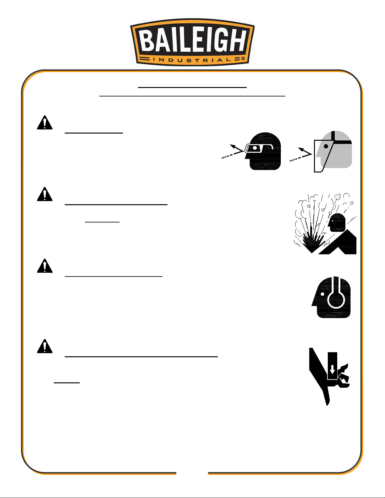
11.Use eye and ear protection. Always wear ISO approved impact safety goggles. Wear a full-
face shield if you are producing metal filings.
12.Do not overreach. Maintain proper footing and balance at all times. DO NOT reach over or
across a running machine.
13.Stay alert. Watch what you are doing and use common sense. DO NOT operate any tool or
machine when you are tired.
14.Check for damaged parts. Before using any tool or machine, carefully check any part that
appears damaged. Check for alignment and binding of moving parts that may affect proper
machine operation.
15.Observe work area conditions. DO NOT use machines or power tools in damp or wet
locations. Do not expose to rain. Keep work area well lighted. DO NOT use electrically
powered tools in the presence of flammable gases or liquids.
16.Keep children away. Children must never be allowed in the work area. DO NOT let them
handle machines, tools, or extension cords.
17.Store idle equipment. When not in use, tools must be stored in a dry location to inhibit rust.
Always lock up tools and keep them out of reach of children.
18.DO NOT operate machine if under the influence of alcohol or drugs. Read warning
labels on prescriptions. If there is any doubt, DO NOT operate the machine.
19.DO NOT touch live electrical components or parts.
20.Turn off power before checking, cleaning, or replacing any parts.
21.Be sure all equipment is properly installed and grounded according to national, state, and
local codes.
22.Inspect power and control cables periodically. Replace if damaged or bare wires are
exposed. Bare wiring can kill!
23.DO NOT bypass or defeat any safety interlock systems.
24.Keep visitors a safe distance from the work area.

6
6
TECHNICAL SPECIFICATIONS
Mild Steel Capacity
14 ga.
Aluminum Capacity
12 ga.
Movement
Hydraulic Down/Close, Pneumatic Up/Open
Throat Depth
6" (152mm)
Stand
Included
Electrical Power
240V, 50hz, 15A
Motor
2hp (1.5kw)
Air Supply
80-120psi (5.5-8.2bar)
Shipping Weight
300 lbs.
Shipping Dimensions
60" x 44" x 66"
Note: The photos and illustrations used in this manual are representative only and
may not depict the actual color, labeling or accessories and may be intended to illustrate
technique only.
Note: The specifications and dimensions presented here are subject to change
without prior notice due to improvements of our products.
UNPACKING AND CHECKING CONTENTS

7
7
Your Baileigh machine is shipped complete. Separate all parts from the packing material and
check each item carefully. Make certain all items are accounted for before discarding any
packing material.
Cleaning
Your machine may be shipped with a rustproof waxy coating and/or grease on the exposed
unpainted metal surfaces. Fully and completely remove this protective coating using a
degreaser or solvent cleaner. Moving items will need to be moved along their travel path to
allow for cleaning the entire surface. For a more thorough cleaning, some parts will occasionally
have to be removed. DO NOT USE acetone or brake cleaner as they may damage painted
surfaces.
Follow manufacturer’s label instructions when using any type of cleaning product. After cleaning,
wipe unpainted metal surfaces with a light coating of quality oil or grease for protection.
Important: This waxy coating is NOT a lubricant and will cause the machine to
stick and lose performance as the coating continues to dry.
TRANSPORTING AND LIFTING
WARNING:
SUFFOCATION HAZARD! Immediately discard any plastic
bags and packing materials to eliminate choking and suffocation hazards to children
and animals.
If any parts are missing, DO NOT place the machine into service until the missing parts
are obtained and installed correctly.
WARNING: DO NOT USE gasoline or other petroleum products to clean
the machine. They have low flash points and can explode or cause fire.
CAUTION: When using cleaning solvents work in a well-ventilated area.
Many cleaning solvents are toxic if inhaled.
GAS

8
8
Follow these guidelines when lifting with truck or trolley:
•The lift truck must be able to lift at least 1.5 – 2 times
the machines gross weight.
•Make sure the machine is balanced. While
transporting, avoid rough or jerky motion, and maintain
a safe clearance zone around the transport area.
•Use a fork lift with sufficient lifting capacity and forks
that are long enough to reach the complete width of
the machine.
•Remove the securing bolts that attach the machine to
the pallet.
•Approaching the machine from the side, lift the machine on the frame taking care that there
are no cables or pipes in the area of the forks.
•Move the machine to the required position and lower gently to the floor.
•Level the machine so that all the supporting feet are taking the weight of the machine and no
rocking is taking place.
INSTALLATION
IMPORTANT:
Consider the following when looking for a suitable location to place the machine:
•Overall weight of the machine.
•Weight of material being processed.
•Sizes of material to be processed through the machine.
•Space needed for auxiliary stands, work tables, or other machinery.
•Clearance from walls and other obstacles.
•Maintain an adequate working area around the machine for safety.
•Have the work area well illuminated with proper lighting.
•Keep the floor free of oil and make sure it is not slippery.
NOTICE: Lifting and carrying operations should be carried out by skilled workers, such as a
truck operator, crane operator, etc. If a crane is used to lift the machine, attach the lifting chain
carefully, making sure the machine is well balanced.

9
9
•Remove scrap and waste materials regularly, and make sure the work area is free from
obstructing objects.
•If long lengths of material are to be fed into the machine, make sure that they will not extend
into any aisles.
•LEVELING: The machine should be sited on a level, concrete floor. Provisions for securing it
should be in position prior to placing the machine. The accuracy of any machine depends on
the precise placement of it to the mounting surface.
•FLOOR: This machine distributes a large amount of weight over a small area. Make certain
that the floor is capable of supporting the weight of the machine, work stock, and the
operator. The floor should also be a level surface. If the unit wobbles or rocks once in place,
be sure to eliminate by using shims.
•WORKING CLEARANCES: Take into consideration the size of the material to be
processed. Make sure that you allow enough space for you to operate the machine freely.
•POWER SUPPLY PLACEMENT: The power supply should be located close enough to the
machine so that the power cord is not in an area where it would cause a tripping hazard. Be
sure to observe all electrical codes if installing new circuits and/or outlets.
Anchoring the Machine
•Once positioned, anchor the machine to the floor, as shown in
the diagram. Use bolts and expansion plugs or sunken tie rods
that connect through and are sized for the holes in the base of
the stand.
•This machine requires a solid floor such as concrete at a
minimum of 4” (102mm) thick.
.31"
(7.87mm)
.50"
(12.7mm)

10
10
GETTING TO KNOW YOUR MACHINE
Item
Description
Function
A
Foot Pedal
Press the pedal to clamp the jaws together
B
Down Solenoid
Energized when clamping
C Cylinder
Extends with hydraulic pressure when clamping.
Retracts with pneumatic pressure.
D
Gap Adjustment
Increases or decrease the jaw gap.
E
Jaw
Stretch or shrink material
F
ON/OFF Switch
Starts and stops the motor.
A
B
C
D
E
F

11
11
ASSEMBLY AND SET UP
Tooling Installation:
This set up show how the tools should be
installed for shrinking. Notice the marking “X” is
pointing toward each other in both the top and
bottom die sets.
Also notice that the screw heads (A) point away
from the material gap (B).
WARNING: For your own safety, DO NOT connect the machine to the
power source until the machine is completely assembled and you read and
understand the entire instruction manual.
X
A
B
A
X

12
12
In this view it shows the top die assemblies removed
so you can see the jaw orientation. The jaws with
serrations are to be used for shrinking.
In this view it will shows how to remove the jaw caps.
Insert a screwdriver into the machined slot to break
the magnetic force.

13
13
Once the force from the magnet is released, grab
onto the assembly and remove.
In this view it shows the jaws installed for
stretching. Note that the markings “U” are now
pointing together, This is the reversing of the
jaws from shrinking.
U

14
14
Here you will see both top and bottom
mechanisms installed for stretching. Both show
the “U” pointing at each other
Also notice that the screw heads (A) point away
from the material gap (B).
Here is a completed setup for stretching.
JAWS
•The jaw block assemblies should be lightly
lubricated so that they will slide freely and evenly.
Use a 40-weight motor oil or similar.
•Clean the blocks regularly to prevent them from
collecting dirt and becoming sticky.
•The pads should be kept clean and dry. If the
pads become oily or grease the will slip on the
material. Use a mild solvent to remove any oil or
grease.
•Use the Square pads for Stretching.
•Use the Serrated pads for Shrinking.
U
A
B
A
U

15
15
ELECTRICAL
Power Specifications
Your machine is wired for 240 volts, 50hz alternating current. Before connecting the machine to
the power source, make sure the power source is OFF.
Before switching on the power, you must check the voltage and frequency of the power to see if
they meet with the requirement, the allowed range for the voltage is ±5%, and for the frequency
is ±1%.
Considerations
•Observe local electrical codes when connecting the machine.
•The circuit should be protected with a time delay fuse or circuit breaker with an amperage
rating slightly higher than the full load current of machine.
•A separate electrical circuit should be used for your machines. Before connecting the motor
to the power line, make sure the switch is in the “OFF” position and be sure that the electric
current is of the same characteristics as indicated on the machine.
•All line connections should make good contact. Running on low voltage will damage the
motor.
•In the event of a malfunction or breakdown, grounding provides a path of least resistance for
electric current to reduce the risk of electric shock. This machine is equipped with an electric
cord having an equipment-grounding conductor and a grounding plug. The plug must be
plugged into a matching outlet that is properly installed and grounded in accordance with all
local codes and ordinances.
CAUTION: HAVE ELECTRICAL UTILITIES CONNECTED TO MACHINE BY
A CERTIFIED ELECTRICIAN!
Check if the available power supply is the same as listed on the machine nameplate.
WARNING: Make sure the grounding wire (green) is properly connected
to avoid electric shock. DO NOT switch the position of the green grounding wire if any
electrical plug wires are switched during hookup.
WARNING: In all cases, make certain the receptacle in question is
properly grounded. If you are not sure, have a qualified electrician check the
receptacle.

16
16
•Improper connection of the equipment-grounding conductor can result in risk of electric
shock. The conductor with insulation having an outer surface that is green with or without
yellow stripes is the equipment-grounding conductor. If repair or replacement of the electric
cord or plug is necessary, do not connect the equipment-grounding conductor to a live
terminal.
•Check with a qualified electrician or service personnel if the grounding instructions are not
completely understood, or if in doubt as to whether the machine is properly grounded.
•Repair or replace damaged or worn cord immediately.
Extension Cord Safety
Extension cord should be in good condition and meet the minimum wire gauge requirements listed
below:
LENGTH
AMP RATING
25ft
50ft
100ft
1-12
16
16
14
13-16
14
12
12
17-20
12
12
10
21-30
10
10
No
WIRE GAUGE
An undersized cord decreases line voltage, causing loss of power and overheating. All cords
should use a ground wire and plug pin. Replace any damaged cords immediately.
Power cord connection:
1. Turn the main disconnect switch on the control panel to the OFF position.
2. Unwrap the power cord and route the cord away from the machine toward the power supply.
a. Route the power cord so that it will NOT become entangled in the machine in any
way.
b. Route the cord to the power supply in a way that does NOT create a trip hazard.
3. Connect the power cord to the power supply and check that the power cord has not been
damaged during installation.
4. When the machine is clear of any obstruction. The main power switch may be turn ON to test
the operation. Turn the switch OFF when the machine is not in operation.

17
17
OPERATION
1. Connect an air supply with 80-120psi (5.5-8.2bar). This will fully open the gap between the
jaws.
2. Install the jaws for either shrinking or stretching as desired.
3. Use the hand wheel to set the gap between the upper and lower jaws to allow the material to
move easily between them when the jaws are fully open.
4. Practice with the material and place the foot pedal in a location which is comfortable for
work. (A comfortable location will allow the operator to be balanced and in control of the
material at all times.)
5. Start the hydraulics and begin to form the material by pressing on the foot pedal. The foot
pedal may be held for a full cycle or be released at any time. When the pedal is released, the
air pressure will retract the ram lift and open the jaws. PRACTICE.
Operating Tips
The function of this tool is to shrink or stretch sheet metal up to 14ga. (1.9mm).
The principal operation is made when the sheet work piece is placed between the jaws and then
applying and releasing force with the foot on and off of the foot pedal. The work piece is moved
as required each time the foot pedal is released. By moving smoothly, you will be able to make
smooth shapes quickly and easily. PRACTICE.
Do a quick test by stepping on the foot pedal and ensuring that the jaws bite down and pull apart
for the stretcher. For the shrinker the jaws should bite down and squeeze together. The jaws
should return to their open relaxed position between strokes and when the foot pedal is
released.
WARNING:DO NOT step on the foot pedal without having work material
between the jaws. The jaws may chip or break causing injury from flying objects.
CAUTION: Always wear proper eye protection with side shields, safety
footwear, and leather gloves to protect from burrs and sharp edges.
Keep hands and fingers clear of the dies.
When handling large heavy sheets make sure they are properly supported.

18
18
Try using the tool with a sample piece of metal to get a feel for how it operates. Place the
material in the middle of the jaw box and step down on the foot pedal to form the metal. Work
the leading edge of the material first to break down the initial resistance of the metal. Move the
metal back and forth until the desired radius is obtained. You can control the pressure exerted
on the metal by how tight the gap is set between the jaw and how long you hold down the foot
pedal.
The jaws have fine toothed edges to hold the piece part in place. Marks left on your piece part
can be removed with either an abrasive cloth or a wheel for appearance.
MATERIAL SELECTION
When selecting materials keep these instructions in mind:
•Material must be clean and dry. (without oil)
•Material should have a smooth surface, so it processes easily.
•Dimensional properties of material must be consistent and not exceed the machine capacity
values.
•Chemical structure of material must be consistent.
•Buy certificated steel from the same vendor when possible.
CAUTION: It must be determined by the customer that materials being
processed through the machine are NOT
potentially hazardous to operator or
personnel working nearby.
This manual suits for next models
1
Table of contents
Other Baileigh Industrial Equipment manuals

Baileigh
Baileigh EW-30 User manual

Baileigh
Baileigh BB-7216M User manual

Baileigh
Baileigh TN-400X3 Service manual

Baileigh
Baileigh BB-4816M-V2 User manual

Baileigh
Baileigh HPB-20 User manual

Baileigh
Baileigh BP-3305CNC User manual

Baileigh
Baileigh BV-6I User manual

Baileigh
Baileigh HARE&FORBES TN-300 User manual

Baileigh
Baileigh VM-936E-1 User manual

Baileigh
Baileigh SR-5016M User manual