Baileigh B-CART-TB User manual

Assembly and Parts Manual
Cart Models
B-CART-TB, B-CART-MF, & B-CART-CM
© 2022 Baileigh Industrial
REPRODUCTION OF THIS MANUAL IN ANY FORM WITHOUT WRITTEN APPROVAL OF BAILEIGH INDUSTRIAL IS
PROHIBITED. Baileigh Industrial does not assume and hereby disclaims any liability for any damage or loss caused
by an omission or error in this Operator’s Manual, resulting from accident, negligence, or other occurrence.
Edition 2 06/2023
Edition 1 04/2022
Baileigh Industrial
P.O. Box 531
Manitowoc, WI 54221-0531
Phone: 920.684.4990
Fax: 920.684.3944
Baileigh-Sales@jpwindustries.com

2
TABLE OF CONTENTS
1.0 Important Safety Instructions ................................................................................... 3
2.0 General Notes ......................................................................................................... 3
3.0 Technical Support .................................................................................................... 4
4.0 Unpacking ................................................................................................................ 4
5.0 Assembly ................................................................................................................. 4
5.1 Model B-CART-TB ............................................................................................ 4
5.2 Model B-CART-MF ........................................................................................... 7
5.3 Model B-CART-CM ......................................................................................... 10
6.0 Replacement Parts ................................................................................................ 12
6.1.1 B-CART-TB-Exploded View ......................................................................... 13
6.1.2 B-CART-TB-Parts List .................................................................................. 14
6.2.1 B-CART-MF-Exploded View ........................................................................ 15
6.2.2 B-CART-MF-Parts List ................................................................................. 16
6.3.1 B-CART-CM-Exploded View ........................................................................ 17
6.3.2 B-CART-CM-Parts List ................................................................................. 18
7.0 Warranty ................................................................................................................ 19

3
1.0 IMPORTANT SAFETY INSTRUCTIONS
1. Read and understand the entire owner’s
manual before attempting assembly or use.
2. Read and understand the warnings posted
on the cart and in this manual. Failure to
comply with all warnings may cause serious
injury or damage to the cart.
3. Replace the warning labels if they become
obscured or removed.
4. Do not exceed the rated capacities.
Rated capacities: Side shelf – 15 lb. (7 kg);
Middle shelf – 100 lb. (45 kg); Top shelf –
100 lb. (45 kg); Cart base – 425 lb. (193 kg)
5. Avoid off-center or top-heavy loading.
6. Use only on hard, level surfaces.
7. Inspect and ensure all fasteners are secure
and tight.
8. Do not modify cart.
9. Lock wheel casters after positioning cart.
2.0 GENERAL NOTES
After receiving your equipment, remove the protective container. Do a complete visual inspection, and if
damage is noted, photograph it for insurance claims and contact your carrier at once, requesting
inspection. Also contact Baileigh Industrial and inform them of the unexpected occurrence. Temporarily
suspend installation.
Take necessary precautions while loading / unloading or moving the machine to avoid any injuries.
Your machine is designed and manufactured to work smoothly and efficiently. Following proper maintenance
instructions will help ensure this. Try and use original spare parts, whenever possible, and most importantly;
DO NOT overload the machine or make any modifications.
Note: This symbol refers to useful information throughout the manual.

4
3.0 TECHNICAL SUPPORT
Our technical support department can be
reached at 920.684.4990. Tech Support
handles questions on setup, schematics,
warranty issues, and individual parts needs.
For specific application needs or future machine
purchases contact the Sales Department at:
Phone: 920.684.4990, or Fax: 920.684.3944.
Note: The illustrations used in this
manual are representative only and may not
depict the actual labeling or accessories and
may be intended to illustrate technique only.
Note: The specifications and
dimensions presented here are subject to
change without prior notice due to improvements
of our products.
4.0 UNPACKING
Separate all parts from the packing material and check
each item carefully. If any damage is found, notify your
dealer immediately. Do not use if any parts are
damaged. Make certain all items are accounted for
before discarding any packing material.
5.0 ASSEMBLY
5.1 Model B-CART-TB
Clean all rust-protected surfaces with a mild solvent.
1. Using sixteen M10 x 25 Hex Flange Bolts (item
#6), attach the eight Die Rods (item #10) to the
Side Panels (item #3) as shown in Figure 4-1.
Make sure the flanged ends of the Side Panels are
facing out. Do not fully tighten bolts at this time.
Figure 4-1
2. Using six M8 x 16 Hex Flange Bolts (item #5) and
six M8 Flanged Nylock Hex Nuts (item #2), install
Top Tray to Side Panel assembly as shown in
Figure 4-2. Do not full tighten nuts at this time.
Figure 4-2

5
3. Using four M8 x 20 Hex Flange Bolts (item #22)
and four M8 Flanged Nylock Hex Nuts (item #2),
attach the Handle (item #21) to the Side Panel
(item #3) containing the Baileigh logo plate. Only
fully tighten these four bolts and nuts at this
time.
Figure 4-3
4. Turn the cart assembly upside down.
CAUTION: Cart is heavy. To avoid injury,
use two or more people to turn cart to upside
down.
Turn the Base (item #11) upside down and place
on the cart assembly as shown in Figure 4-4.
Make sure the axle-end of base is over the Side
Panel that does not have the handle.
Figure 4-4
5. Align the center mounting hole on each Side Panel
flange with the center mounting hole on each end
of the Base (see Figure 4-5). Attach using two
Round-Head Square-Neck Carriage Bolts (item
#4) and two M10 Nylock Hex Nuts (item #16). Do
not fully tighten nuts at this time.
Figure 4-5
6. Place the Casters (item #17) in the corners of the
Base as shown in Figure 4-6. Align the caster
mounting holes with the mounting holes in the
Side Panel flange and Base. Attach both Casters
using eight Round-Head Square-Neck Carriage
Bolts (item #4) and eight M10 Nylock Hex Nuts
(item #16). Do not fully tighten nuts at this time.
Figure 4-6

6
7. On the Axle end of the cart, insert four Round-
Head Square-Neck Carriage Bolts (item #4)
through the mounting holes in the Side Panel
flange and Base (see Figure 4-7). Attach bolts
using four M10 Flanged Nylock Hex Nuts (item
#16). Fully tighten the sixteen M10 x 25 Hex
Flange Bolts (item #6) from step 1 and the
fourteen M10 Flanged Nylock Hex Nuts (item
#16) from steps 5, 6, and 7.
Figure 4-7
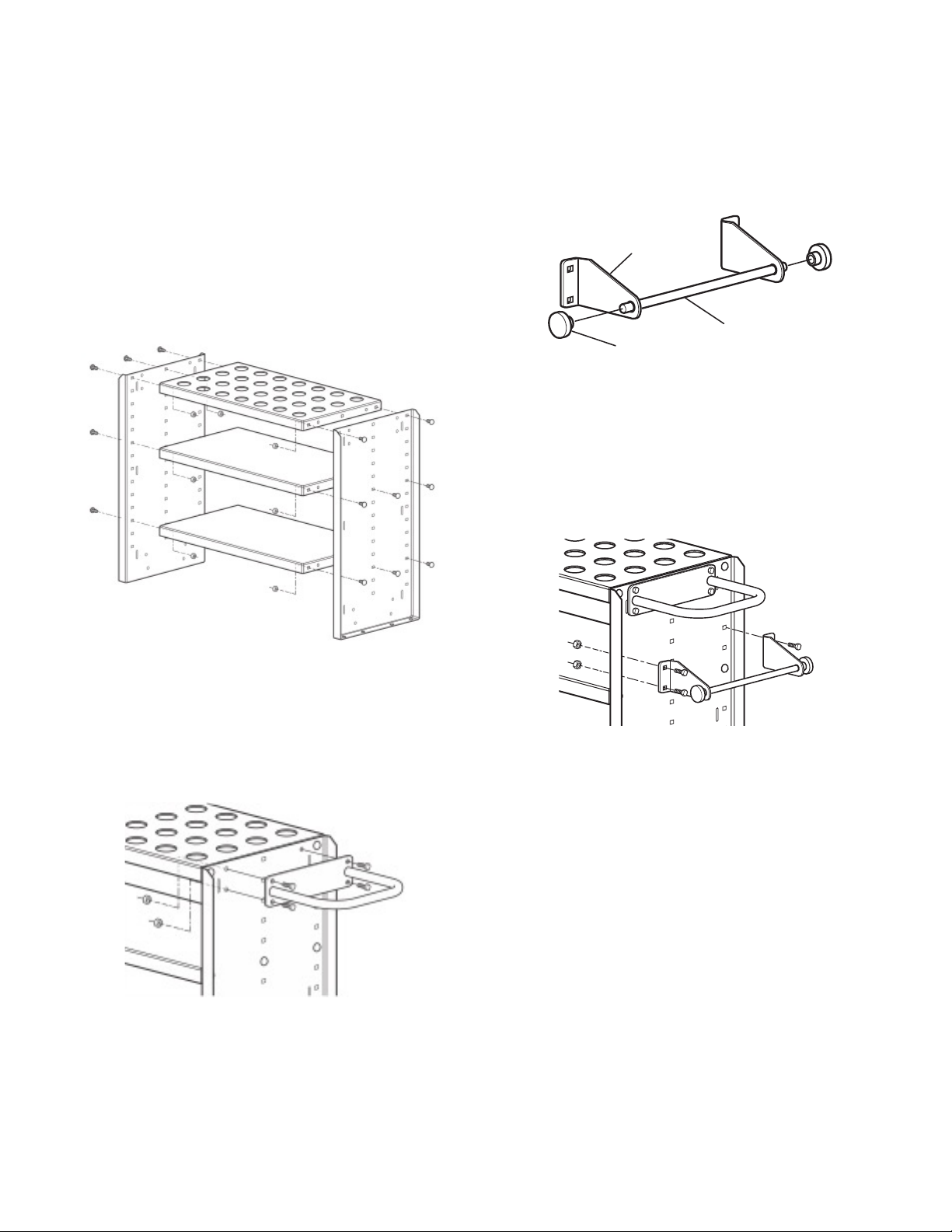
8. Loosen the set screw (item #14) in the four Limit
Rings (item #15) (see Figure 4-8). Slide a Limit
Ring over each end of the Axle, followed by a
Wheel (item #13) and the remaining Limit Ring
(see Figure 4-8). Snug the Limit Rings and Wheels
to the Base. Fully tighten the Limit Ring set
screws to the Axle.
Figure 4-8
9. Turn the cart assembly over to the upright position.
Fully tighten the six M8 Flanged Nylock Hex
Nuts (item #2) from step 2.
CAUTION: Cart is heavy. To avoid injury,
use two or more people to return cart to
upright position.
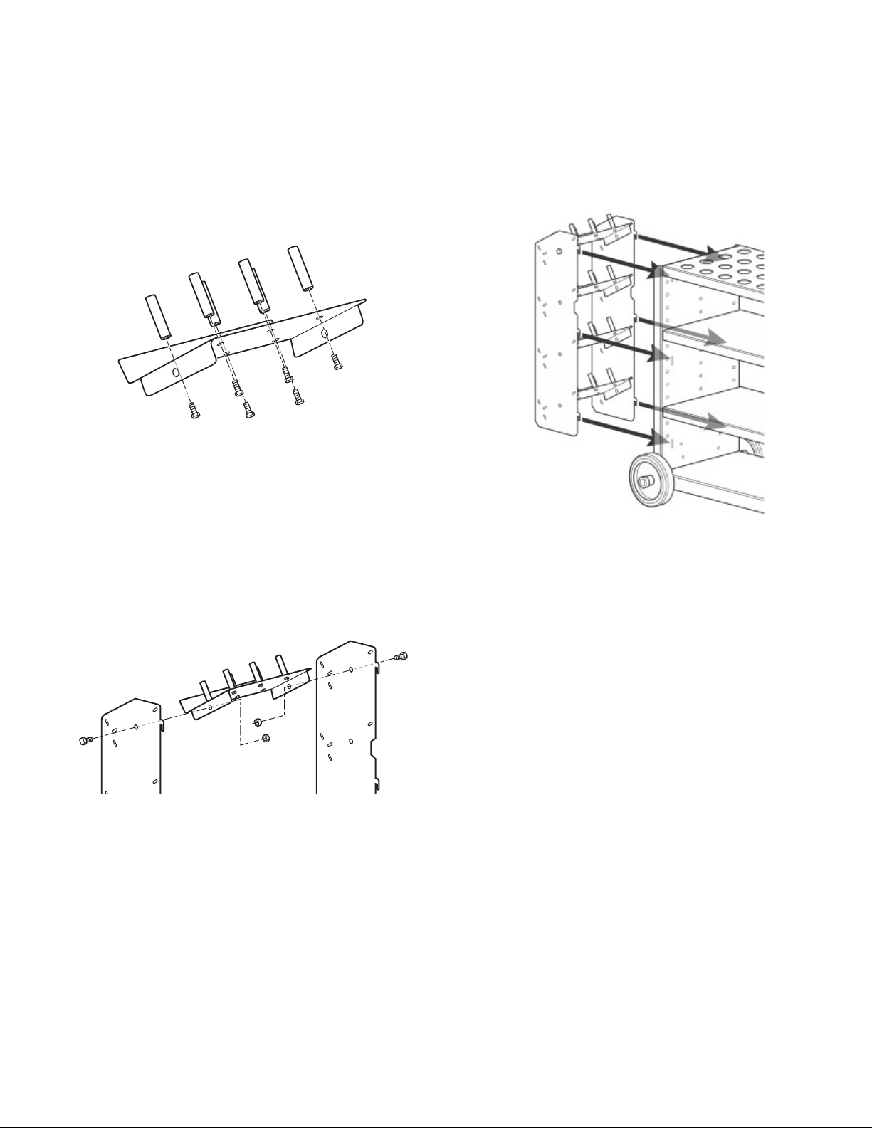
10. Assemble the Angled Tray assembly as shown in
Figure 4-9. Use eight M8 x 16 Hex Flange Bolts
(item #5) and eight M8 Flanged Nylock Hex Nuts
(item #2) to attach the Angled Trays (item #8) to
the Hook Panels (item #7). Make sure to align and
insert the tabs on the Angled Trays into the correct
slots in the Hook Panels. When all tray tabs are
positioned correctly, fully tighten the eight M8
x 16 Hex Flange Bolts (item #5) and eight M8
Flanged Nylock Hex Nuts (item #8). Place
Angled Tray Rubber Mats (item #9) on to each
angled tray.
Figure 4-9
11. Insert the six hook tabs on the Angled Tray
Assembly into the vertical slots on the Side Panel
(see Figure 4-10). Be sure to use the Side Panel
that does not have the handle. When all six hook
tabs are inserted, press the Angled Tray Assembly
down to engage the hooks and attach to the Side
Panel.
Figure 4-10
12. Place a Top Tray Rubber Mat (item #23) into the
Top Tray (item #1).
Set ScrewWheel
Limit Ring

7
5.2 Model B-CART-MF
Clean all rust-protected surfaces with a mild solvent.
1. Using seventeen M8 x 20 Round-Head Square-
Neck Carriage Bolts (item #3) with M8 Flanged
Nylock Hex Nuts (item #2), attach the two Shelves
(item #18) and Tooling Insert Tray (item #1) to the
Side Panels (item #4) as shown in Figure 4-11.
NOTE: The two shelves (item #18) can be
mounted at your desired height. They can also be
installed upside down and used as trays. Make
sure the flanged ends of the Side Panels are
facing out. Do not fully tighten nuts at this time.
Figure 4-11
2. Using four M8 x 25 Hex Flange Bolts (item #5) with
M8 Flanged Nylock Hex Nuts (item #2), attach the
Handle (item #6) to the Side Panel (item #4) as
shown in Figure 4-12. Note: The top two bolts will
pass through the Tooling Insert Tray. Do not fully
tighten nuts at this time.
Figure 4-12
3. Insert threaded ends of the Rod (item #9) through
hole in each Rod Mount (items #8 & #10) and
tighten a Rod Knob (item #7) onto each threaded
end. Make sure the Rod Mounts are oriented as
shown in Figure 4-13 with the flanged ends
pointing out.
Figure 4-13
4. Using four M8 x 20 Round-Head Square-Neck
Carriage Bolts (item #3) with M8 Flanged Nylock
Hex Nuts (item #2), and attach the Rod assembly
to the Side Panel, just below the Handle, as shown
in Figure 4-14. Only fully tighten these four
bolts and nuts at this time.
Figure 4-14
Rod
Rod Mount
Rod Knob

8
5. Turn the cart assembly upside down.
CAUTION: Cart is heavy. To avoid injury,
use two or more people to turn cart to upside
down.
Turn the Base (item #12) upside down and place
on the cart assembly as shown in Figure 4-15.
Make sure the Axle is over the Side Panel that
does not have the handle.
Figure 4-15
6. Align the mounting holes on each Side Panel
flange with the mounting holes on each end of the
Base. Place the Casters (item #13) in the corners
of the Base as shown in Figure 4-16. Align the
Caster mounting holes with the mounting holes in
the Side Panel flange and Base. Attach Casters,
Base, and Side Panel using eight M8 x 25 Round-
Head Square-Neck Carriage Bolts (item #11) with
M8 Flanged Nylock Hex Nuts (item #2), as shown
in Figure 4-16. Attach the axle-end of the Base to
the Side Panel using four M8 x 20 Round-Head
Square-Neck Carriage Bolts (item #3) with M8
Flanged Nylock Hex Nuts (item #2). Fully tighten
all nuts from steps 1 and 2, then fully tighten
all nuts from step 6.
Figure 4-16
7. Loosen the set screw (item #17) in the four Limit
Rings (item #16) (see Figure 4-17). Slide a Limit
Ring over each end of the Axle, followed by a
Wheel (item #15) and the remaining Limit Ring.
Snug the Limit Rings and Wheels to the Base.
Fully tighten the Limit Ring set screws to the
Axle.
Figure 4-17
8. Turn the cart assembly over to the upright position.
CAUTION: Cart is heavy. To avoid injury,
use two or more people to return cart to
upright position.
Set ScrewWheel
Limit Ring

9
9. Attach six Angled Tray Pins (item #21) to each of
the four Angled Trays (item #20) as shown in
Figure 4-18. Align the threaded hole of each pin
with the mounting holes on each Angled Tray.
Insert a M6 x 12 Hex Flange Bolt (item #22)
through the bottom of the Angled Tray and into the
Pin. Fully tighten the bolt to secure the Pin in
place. When finished, you will have four Angled
Trays with six Pins installed on each.
Figure 4-18
10. Use eight M8 x 16 Hex Flange Bolts (item #24)
with M8 Flanged Nylock Hex Nuts (item #2), and
attach the four Angled Trays (item #20) to the two
Hook Panels (item #23) as shown in Figure 4-19.
Make sure to align and insert the tabs on the
Angled Trays into the correct slots in the Hook
Panels. When all tray tabs are positioned
correctly, fully tighten the eight M8 x 16 Hex
Flange Bolts (item #24) and eight M8 Flanged
Nylock Hex Nuts (item #2).
Figure 4-19
11. Insert the six hook tabs on the Angled Tray
Assembly into the vertical slots on the Side Panel
(see Figure 4-20). Be sure to use the Side Panel
that does not have the handle. When all six hook
tabs are inserted, press the Angled Tray Assembly
down to engage the hooks and attach to the Side
Panel.
Figure 4-20
12. Place desired Tooling Inserts (items #25, 26, & 27)
into holes in Tooling Insert Tray (item #1).
13. Place a Shelf Rubber Mat (item #19) on the top
surface of each Shelf (item #18).

10
5.3 Model B-CART-CM
Clean all rust-protected surfaces with a mild solvent.
1. Using seventeen M8 x 20 Round-Head Square-
Neck Carriage Bolts (item #3) with M8 Flanged
Nylock Hex Nuts (item #2), attach the two Shelves
(item #18) and Tooling Insert Tray (item #1) to the
Side Panels (item #4) as shown in Figure 4-21.
NOTE: The two shelves (item #18) can be
mounted at your desired height. They can also be
installed upside down and used as trays. Make
sure the flanged ends of the Side Panels are
facing out. Do not fully tighten nuts at this time.
Figure 4-21
2. Using four M8 x 25 Hex Flange Bolts (item #5) with
M8 Flanged Nylock Hex Nuts (item #2), attach the
Handle (item #6) to the Side Panel (item #4) as
shown in Figure 4-22. Note: The top two bolts will
pass through the Tooling Insert Tray. Do not fully
tighten nuts at this time.
Figure 4-22
3. Insert threaded ends of the Rod (item #9) through
hole in each Rod Mount (items #8 & #10) and
tighten a Rod Knob (item #7) onto each threaded
end. Make sure the Rod Mounts are oriented as
shown in Figure 4-23 with the flanged ends
pointing out.
Figure 4-23
4. Using four M8 x 20 Round-Head Square-Neck
Carriage Bolts (item #3) with M8 Flanged Nylock
Hex Nuts (item #2), and attach the Rod assembly
to the Side Panel, just below the Handle, as shown
in Figure 4-24. Only fully tighten these four
bolts and nuts at this time.
Figure 4-24
5. Turn the cart assembly upside down.
CAUTION: Cart is heavy. To avoid injury,
use two or more people to turn cart to upside
down.
Turn the Base (item #12) upside down and place
on the cart assembly as shown in Figure 4-25.
Make sure the Axle is over the Side Panel that
does not have the handle.
Rod
Rod Mount
Rod Knob

11
Figure 4-25
6. Align the mounting holes on each Side Panel
flange with the mounting holes on each end of the
Base. Place the Casters (item #13) in the corners
of the Base as shown in Figure 4-26. Align the
Caster mounting holes with the mounting holes in
the Side Panel flange and Base. Attach Casters,
Base, and Side Panel using eight M8 x 25 Round-
Head Square-Neck Carriage Bolts (item #11) with
M8 Flanged Nylock Hex Nuts (item #2), as shown
in Figure 4-26. Attach the axle-end of the Base to
the Side Panel using four M8 x 20 Round-Head
Square-Neck Carriage Bolts (item #3) with M8
Flanged Nylock Hex Nuts (item #2). Fully tighten
all nuts from steps 1 and 2, then fully tighten
all nuts from step 6.
Figure 4-26
7. Loosen the set screw (item #17) in the four Limit
Rings (item #16) (see Figure 4-27). Slide a Limit
Ring over each end of the Axle, followed by a
Wheel (item #15) and the remaining Limit Ring.
Snug the Limit Rings and Wheels to the Base.
Fully tighten the Limit Ring set screws to the
Axle.
Figure 4-27
8. Turn the cart assembly over to the upright position.
CAUTION: Cart is heavy. To avoid injury,
use two or more people to return cart to
upright position.
Set ScrewWheel
Limit Ring

12
9. Using eight M8 x 20 Round-Head Square-Neck
Carriage Bolts (item #3) with M8 Flanged Nylock
Hex Nuts (item #2), attach two Rear Trays (item
#21) to Rear Tray Mounting Brackets (item #20)
as shown in Figure 4-28. Do not fully tighten
nuts at this time.
Figure 4-28
10. Using eight M8 x 20 Round-Head Square-Neck
Carriage Bolts (item #3) with M8 Flanged Nylock
Hex Nuts (item #2), attach both Rear Tray
Assemblies to the Side Panel that doesn’t have
the handle (see Figure 4-29). Provide desired
space between trays. Fully tighten all nuts
applied in steps 9 & 10.
Figure 4-29
11. Place Rear Tray Rubber Mats (item #22) into each
RearTray.
12. Place desired Tooling Inserts (items #23, 24, & 25)
into holes in Tooling Insert Tray (item #1).
13. Place a Shelf Rubber Mat (item #19) on the top
surface of each Shelf (item #18).
6.0 REPLACEMENT PARTS
Replacement parts are listed on the following pages. To order parts or reach our service department, call 1-800-274-
6848 Monday through Friday, 8:00 a.m. to 5:00 p.m. CST. Having the Model Number and Serial Number of your
machine available when you call will allow us to serve you quickly and accurately.
Non-proprietary parts, such as fasteners, can be found at local hardware stores, or may be ordered from Baileigh
Industrial.
Some parts are shown for reference only and may not be available individually.

13
6.1.1 B-CART-TB – Exploded View

14
6.1.2 B-CART-TB – Parts List
Item No. Part No. Description Qty
1 BA1-657 ....................................... Top Tray .................................................................................... 1
2 TS-1541031 ................................. Flanged Nylock Hex Nut, M8 ................................................... 18
3 BA1-658 ....................................... Side Panel ................................................................................. 2
4 BA1-659 ....................................... Round-Head Square-Neck Carriage Bolt, M10 x 25 ................ 14
5 BA1-660 ....................................... Hex flange Bolt, M8 x 16 .......................................................... 14
6 BA1-661 ....................................... Hex flange Bolt, M10 x 25 ........................................................ 16
7 BA1-662 ....................................... Hook Plate ................................................................................ 2
8 BA1-663 ....................................... Angled Tray ............................................................................... 4
9 BA1-664 ....................................... Angled Tray Rubber Mat ........................................................... 4
10 BA1-665 ....................................... Die Rod ..................................................................................... 8
11 BA1-666 ....................................... Base .......................................................................................... 1
12 BA1-667 ....................................... Axle ........................................................................................... 1
13 BA1-668 ....................................... Wheel ........................................................................................ 2
14 TS-1490011 ................................. Hex Socket Set Screw, M8 x 8 ................................................. 4
15 BA1-669 ....................................... Limit Ring .................................................................................. 4
16 TS-2342101 ................................. Nylock Hex Nut, M10 ............................................................... 14
17 BA1-670 ....................................... Caster ....................................................................................... 2
18 BA9-PP1912 ................................ Baileigh Logo Plate ................................................................... 1
19 TS-1482031 ................................. Button Socket-Head Cap Screw, M6 x 16 ................................ 4
20 TS-2311061 ................................. Hex Nut, M6 .............................................................................. 4
21 BA1-671 ....................................... Handle ....................................................................................... 1
22 BA1-672 ....................................... Hex Flange Bolt, M8 x 20 .......................................................... 4
23 BA1-673 ....................................... Top Tray Rubber Mat ................................................................ 1
BA1-674 ....................................... Baileigh ID Label (not shown) ................................................... 1
BA1-675 ....................................... B-CART-TB Capacity Decal (not shown) .................................. 1

15
6.2.1 B-CART-MF – Exploded View

16
6.2.2 B-CART-MF – Parts List
Item No. Part No. Description Qty
1 BA1-685 ....................................... Tooling Insert Tray .................................................................... 1
2 TS-1541031 ................................. Flanged Nylock Hex Nut, M8 ................................................... 45
3 BA1-676 ....................................... Round-Head Square-Neck Carriage Bolt, M8 x 20 .................. 33
4 BA1-686 ....................................... Side Panel ................................................................................. 2
5 TS-1490041 ................................. Hex Bolt, M8 x 25 ...................................................................... 4
6 BA1-671 ....................................... Handle ....................................................................................... 1
7 BA1-687 ....................................... Rod Knob .................................................................................. 2
8 BA1-688 ....................................... Rod Mount-Right ....................................................................... 1
9 BA1-689 ....................................... Rod .......................................................................................... 1
10 BA1-690 ....................................... Rod Mount-Left ......................................................................... 1
11 TS-1482031 ................................. Hex Bolt, M6 x 16 ...................................................................... 8
12 BA1-691 ....................................... Base .......................................................................................... 1
13 BA1-692 ....................................... Caster ....................................................................................... 2
14 BA1-693 ....................................... Axle ........................................................................................... 1
15 BA1-668 ....................................... Wheel ........................................................................................ 2
16 BA1-669 ....................................... Limit Ring .................................................................................. 4
17 TS-1524011 ................................. Hex Socket Set Screw, M8 x 8 ................................................. 4
18 BA1-694 ....................................... Shelf .......................................................................................... 2
19 BA1-695 ....................................... Shelf Rubber Mat ...................................................................... 2
20 BA1-663 ....................................... Angled Tray ............................................................................... 4
21 BA1-704 ....................................... Angled Tray Pin ....................................................................... 24
22 BA1-705 ....................................... Hex Flange Bolt, M6 x 12 ......................................................... 24
23 BA1-662 ....................................... Hook Plate ................................................................................ 2
24 BA1-660 ....................................... Metric Hex Flange Screw, M8 x 16 ........................................... 8
25 BA1-699 ....................................... #30/5C Tooling Insert ............................................................... 28
26 BA1-700 ....................................... #40 Tooling Insert .................................................................... 28
27 BA1-701 ....................................... R8 Tooling Insert ...................................................................... 28
28 TS-2311061 ................................. Hex Nut, M6 .............................................................................. 8
29 BA9-PP1912 ................................ Baileigh Logo Plate ................................................................... 2
BA1-706 ....................................... Baileigh ID Label (not shown) ................................................... 1
BA1-707 ....................................... B-CART-MF Capacity Decal (not shown) ................................. 1

17
6.3.1 B-CART-CM – Exploded View

18
6.3.2 B-CART-CM – Parts List
Item No. Part No. Description Qty
1 BA1-685 ....................................... Tooling Insert Tray .................................................................... 1
2 TS-1541031 ................................. Flanged Nylock Hex Nut, M8 ................................................... 51
3 BA1-676 ....................................... Round-Head Square-Neck Carriage Bolt, M8 x 20 .................. 47
4 BA1-686 ....................................... Side Panel ................................................................................. 2
5 TS-1490041 ................................. Hex Bolt, M8 x 25 ...................................................................... 4
6 BA1-671 ....................................... Handle ....................................................................................... 1
7 BA1-687 ....................................... Rod Knob .................................................................................. 2
8 BA1-688 ....................................... Rod Mount-Right ....................................................................... 1
9 BA1-689 ....................................... Rod .......................................................................................... 1
10 BA1-690 ....................................... Rod Mount-Left ......................................................................... 1
11 TS-1482031 ................................. Hex Bolt, M6 x 16 ...................................................................... 8
12 BA1-691 ....................................... Base .......................................................................................... 1
13 BA1-692 ....................................... Caster ....................................................................................... 2
14 BA1-693 ....................................... Axle ........................................................................................... 1
15 BA1-668 ....................................... Wheel ........................................................................................ 2
16 BA1-669 ....................................... Limit Ring .................................................................................. 4
17 TS-1524011 ................................. Hex Socket Set Screw, M8 x 8 ................................................. 4
18 BA1-694 ....................................... Shelf .......................................................................................... 2
19 BA1-695 ....................................... Shelf Rubber Mat ...................................................................... 2
20 BA1-696 ....................................... Rear Tray Mounting Bracket ..................................................... 4
21 BA1-697 ....................................... Rear Tray .................................................................................. 2
22 BA1-698 ....................................... Rear Tray Rubber Mat .............................................................. 2
23 BA1-699 ....................................... #30/5C Tooling Insert ............................................................... 28
24 BA1-700 ....................................... #40 Tooling Insert .................................................................... 28
25 BA1-701 ....................................... R8 Tooling Insert ...................................................................... 28
26 TS-2311061 ................................. Hex Nut, M6 .............................................................................. 8
27 BA9-PP1912 ................................ Baileigh Logo Plate ................................................................... 2
BA1-702 ....................................... Baileigh ID Label (not shown) ................................................... 1
BA1-703 ....................................... B-CART-CM Capacity Decal (not shown) ................................. 1

19
7.0 WARRANTY
Thank you for your purchase from Baileigh Industrial. We hope you find it productive and useful for
a long time to come.
Inspection & Acceptance. Buyer shall inspect all Goods within ten (10) days after receipt thereof. Buyer’s
payment shall constitute final acceptance of the Goods and shall act as a waiver of the Buyer’s rights to
inspect or reject the goods unless otherwise agreed. If Buyer rejects any merchandise, Buyer must first
obtain a Returned Goods Authorization (“RGA”) number before returning any goods to Seller. Goods
returned without an RGA will be refused. Seller will not be responsible for any freight costs, damages to
goods, or any other costs or liabilities pertaining to goods returned without an RGA. Seller shall have the
right to substitute a conforming tender. Buyer will be responsible for all freight costs to and from Buyer and
repackaging costs, if any, if Buyer refuses to accept shipment. If Goods are returned in unsalable condition,
Buyer shall be responsible for full value of the Goods. Buyer may not return any special-order Goods. Any
Goods returned hereunder shall be subject to a restocking fee equal to 30% of the invoice price.
Specifications. Seller may, at its option, make changes in the designs, specifications, or components of
the Goods to improve the safety of such Goods, or if in Seller’s judgment, such changes will be beneficial to
their operation or use. Buyer may not make any changes in the specifications for the Goods unless Seller
approves of such changes in writing, in which event Seller may impose additional charges to implement such
changes.
Limited Warranty. Seller warrants to the original end-user that the Goods manufactured or provided by Seller
under this Agreement shall be free of defects in material or workmanship for a period of twelve (12) months
from the date of purchase, provided that the Goods are installed, used, and maintained in accordance with
any instruction manual or technical guidelines provided by the Seller or supplied with the Goods, if applicable.
The original end-user must give written notice to Seller of any suspected defect in the Goods prior to the
expiration of the warranty period. The original end-user must also obtain an RGA from Seller prior to returning
any Goods to Seller for warranty service under this paragraph. Seller will not accept any responsibility for
Goods returned without an RGA. The original end-user shall be responsible for all costs and expenses
associated with returning the Goods to Seller for warranty service. In the event of a defect, Seller, at its sole
option, shall repair or replace the defective Goods or refund to the original end-user the purchase price for
such defective Goods. Goods are not eligible for replacement or return after a period of 10 days from date
of receipt. The foregoing warranty is Seller’s sole obligation, and the original end-user’s exclusive remedy,
with regard to any defective Goods. This limited warranty does not apply to: (a) die sets, tooling, and saw
blades; (b) periodic or routine maintenance and setup, (c) repair or replacement of the Goods due to normal
wear and tear, (d) defects or damage to the Goods resulting from misuse, abuse, neglect, or accidents, (f)
defects or damage to the Goods resulting from improper or unauthorized alterations, modifications, or
changes; and (f) any Goods that has not been installed and/or maintained in accordance with the instruction
manual or technical guidelines provided by Seller.
EXCLUSION OF OTHER WARRANTIES. THE FOREGOING LIMITED WARRANTY IS IN LIEU OF ALL
OTHER WARRANTIES, EXPRESS OR IMPLIED. ANY AND ALL OTHER EXPRESS, STATUTORY, OR
IMPLIED WARRANTIES, INCLUDING BUT NOT LIMITED TO, ANY WARRANTY OF MERCHANTABILITY
OR FITNESS FOR ANY PARTICULAR PURPOSE ARE EXPRESSLY DISCLAIMED. NO WARRANTY IS
MADE WHICH EXTENDS BEYOND THAT WHICH IS EXPRESSLY CONTAINED HEREIN.
Limitation of Liability. IN NO EVENT SHALL SELLER BE LIABLE TO BUYER OR ANY OTHER PARTY
FOR ANY INCIDENTIAL, CONSEQUENTIAL OR SPECIAL DAMAGES (INCLUDING, WITHOUT
LIMITATION, LOST PROFITS OR DOWN TIME) ARISING FROM OR IN MANNER CONNECTED WITH
THE GOODS, ANY BREACH BY SELLER OR ITS AGENTS OF THIS AGREEMENT, OR ANY OTHER
CAUSE WHATSOEVER, WHETHER BASED ON CONTRACT, TORT OR ANY OTHER THEORY OF
LIABILITY. BUYER’S REMEDY WITH RESPECT TO ANY CLAIM ARISING UNDER THIS AGREEMENT
IS STRICTLY LIMITED TO NO MORE THAN THE AMOUNT PAID BY THE BUYER FOR THE GOODS.

20
Force Majeure. Seller shall not be responsible for any delay in the delivery of, or failure to deliver, Goods
due to causes beyond Seller’s reasonable control including, without limitation, acts of God, acts of war or
terrorism, enemy actions, hostilities, strikes, labor difficulties, embargoes, non-delivery or late delivery of
materials, parts and equipment or transportation delays not caused by the fault of Seller, delays caused by
civil authorities, governmental regulations or orders, fire, lightening, natural disasters or any other cause
beyond Seller’s reasonable control. In the event of any such delay, performance will be postponed by such
length of time as may be reasonably necessary to compensate for the delay.
Installation. If Buyer purchases any Goods that require installation, Buyer shall, at its expense, make all
arrangements and connections necessary to install and operate the Goods. Buyer shall install the Goods in
accordance with any Seller instructions and shall indemnify Seller against any and all damages, demands,
suits, causes of action, claims and expenses (including actual attorneys’ fees and costs) arising directly or
indirectly out of Buyer’s failure to properly install the Goods.
Work By Others; Safety Devices. Unless agreed to in writing by Seller, Seller has no responsibility for labor
or work performed by Buyer or others, of any nature, relating to design, manufacture, fabrication, use,
installation, or provision of Goods. Buyer is solely responsible for furnishing and requiring its employees and
customers to use all safety devices, guards and safe operating procedures required by law and/or as set
forth in manuals and instruction sheets furnished by Seller. Buyer is responsible for consulting all operator
manuals, ANSI or comparable safety standards, OSHA regulations and other sources of safety standards
and regulations applicable to the use and operation of the Goods.
Remedies. Each of the rights and remedies of Seller under this Agreement is cumulative and in addition to
any other or further remedies provided under this Agreement or at law or equity.
Attorney’s Fees. In the event legal action is necessary to recover monies due from Buyer or to enforce any
provision of this Agreement, Buyer shall be liable to Seller for all costs and expenses associated therewith,
including Seller’s actual attorney fees and costs.
Governing Law/Venue. This Agreement shall be construed and governed under the laws of the State of
Wisconsin, without application of conflict of law principles. Each party agrees that all actions or proceedings
arising out of or in connection with this Agreement shall be commenced, tried, and litigated only in the state
courts sitting in Manitowoc County, Wisconsin or the U.S. Federal Court for the Eastern District of Wisconsin.
Each party waives any right it may have to assert the doctrine of “forum non conveniens” or to object to
venue to the extent that any proceeding is brought in accordance with this section. Each party consents to
and waives any objection to the exercise of personal jurisdiction over it by courts described in this section.
Each party waives to the fullest extent permitted by applicable law the right to a trial by jury.
Summary of Return Policy:
• 10 Day acceptance period from date of delivery. Damage claims and order discrepancies will not be
accepted after this time.
• You must obtain a Baileigh Industrial issued RGA number PRIOR to returning any materials.
• Returned materials must be received at Baileigh Industrial in new condition and in original packaging.
• Altered items are not eligible for return.
• Buyer is responsible for all shipping charges.
• A 30% re-stocking fee applies to all returns.
Baileigh Industrial Holdings LLC makes every effort to ensure that our posted specifications, images, pricing,
and product availability are as correct and timely as possible. We apologize for any discrepancies that may
occur. Baileigh Industrial Holdings LLC reserves the right to make any and all changes deemed necessary
in the course of business including but not limited to pricing, product specifications, quantities, and product
availability.
For Customer Service & Technical Support:
Please contact one of our knowledgeable Sales and Service team members at:
(920) 684-4990 or e-mail us at Baileigh-Service@jpwindustries.com
This manual suits for next models
2
Table of contents
Other Baileigh Outdoor Cart manuals
Popular Outdoor Cart manuals by other brands

Home Styles
Home Styles 88 5522 9502 Assembly instructions

sunjoe
sunjoe L-DW047PST-3D Assembly instructions

Power Fist
Power Fist 8781080 user manual

Ohio Steel
Ohio Steel 1690766 Owner's guide and parts list

PLANTCRAFT
PLANTCRAFT MOWCRTPLTAPD1 Instructions & assembly

Gardeners
Gardeners 8594333 quick start guide