© 2021 Baker Hughes Company. All rights reserved. Masoneilan 7700E UA TR Instructions Manual | 7
6. Assembly of a 7700E Positioner on a Valve
•Comply with current national and local regulations for electrical installation work.
•Must be installed and put into service in conformance with EN/IEC 60079-14 and / or national and
local regulations applicable for explosive atmospheres.
•Comply with national and local explosive atmosphere regulations.
•Before carrying out any work on the device, power off the instrument or make sure that the local
conditions in the potentially explosive atmosphere permit the safe opening of the cover.
•Before switching on or after doing any work on the device, always tighten the cover (C) with a
seal (J) in good condition and put back the safety screw (V).
Note: Before installation, check that the device is undamaged. In the event of damage, replace the
defective parts with genuine manufacturer's replacement parts.
If the positioner is shipped alone, the user is responsible for its installation, electrical and pneumatic connections
and its calibration.
Please refer to 28000 Series instruction manual Ref. 30857 for more details.
7. Pneumatic Connection of Positioner 7700E
Make sure that the air supply pressure is suitable for the installation and for the instrument.
When using a positioner, make sure that the air supply pressure matches the one specified on the
serial plate without exceeding 275 kPa (40 psi).
Diameter of tubing required: 4 x 6 mm.
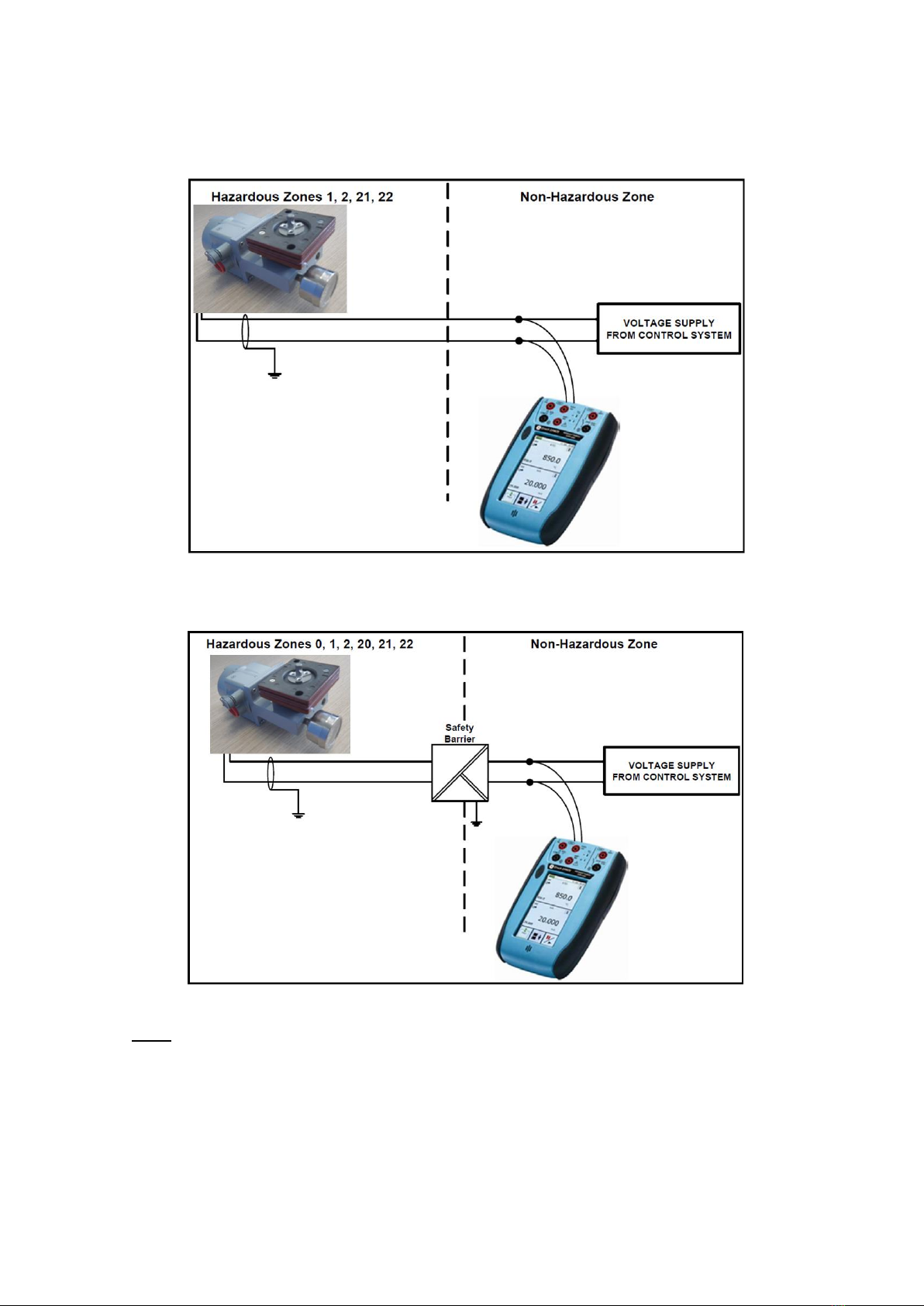
8. Electrical Connection, Installation and Start-Up
•Comply with current national and local regulations for electrical installation work.
•Must be installed and put into service in conformance with national and local regulations
applicable for explosible atmospheres.
•Before carrying out any work on the device, power off the instrument or make sure that the local
conditions in the potentially explosive atmosphere permit the safe opening of the cover.
•Connect the wires to the instrument’s terminals taking care of complying with polarities and
maximum voltage allowed.
•Before switching on or after doing any work on the device, always tighten the cover (C) with a
seal (J) in good condition and put back the safety screw (V).
•Check the earth terminals are well connected.
Note: Before installation, check that the device is undamaged. In the event of damage, replace the
defective parts with genuine manufacturer's replacement parts.