Baldor SERIES 5 User manual

For Catalog os. ID5202-CO, ID5203-CO,
ID5401-CO, ID5402-CO, ID5403-CO, ID5405-CO
Series 5 Inverter
Installation and Operating Manual
M 783

TABLE OF CONTENTS
Section Page
1ntroduction . . . . . . . . . . . . . . . . . . . . . . . . . . . . . . . . . . . . . . . . . . . . . . . . . . . . . . . . . . . . . . . . . . . 4
Safety Notice . . . . . . . . . . . . . . . . . . . . . . . . . . . . . . . . . . . . . . . . . . . . . . . . . . . . . . . . . . . . . . . . . . 7
2Quick-Start nstructions . . . . . . . . . . . . . . . . . . . . . . . . . . . . . . . . . . . . . . . . . . . . . . . . . . . . . . . . . . 8
3 Mounting nstructions . . . . . . . . . . . . . . . . . . . . . . . . . . . . . . . . . . . . . . . . . . . . . . . . . . . . . . . . . . . 14
4 Finger-Safe Cover . . . . . . . . . . . . . . . . . . . . . . . . . . . . . . . . . . . . . . . . . . . . . . . . . . . . . . . . . . . . . . 14
5Electrical Connections nstructions . . . . . . . . . . . . . . . . . . . . . . . . . . . . . . . . . . . . . . . . . . . . . . . . . 15
6 Setting Selectable Jumpers . . . . . . . . . . . . . . . . . . . . . . . . . . . . . . . . . . . . . . . . . . . . . . . . . . . . . . 21
7 Trimpot Adjustments . . . . . . . . . . . . . . . . . . . . . . . . . . . . . . . . . . . . . . . . . . . . . . . . . . . . . . . . . . . . 22
8 Drive Operation . . . . . . . . . . . . . . . . . . . . . . . . . . . . . . . . . . . . . . . . . . . . . . . . . . . . . . . . . . . . . . . 26
9 Diagnostic LEDs . . . . . . . . . . . . . . . . . . . . . . . . . . . . . . . . . . . . . . . . . . . . . . . . . . . . . . . . . . . . . . . 28
Baldor District Offices . . . . . . . . . . . . . . . . . . . . . . . . . . . . . . . . . . . . . . . . . . . . . . . . . . . . . . . . . . . 31
Limited Warranty . . . . . . . . . . . . . . . . . . . . . . . . . . . . . . . . . . . . . . . . . . . . . . . . . . . . . . . . . . . . . . 32
Tables Page
1 Standard Features . . . . . . . . . . . . . . . . . . . . . . . . . . . . . . . . . . . . . . . . . . . . . . . . . . . . . . . . . . . . . . 4
2 Performance Features . . . . . . . . . . . . . . . . . . . . . . . . . . . . . . . . . . . . . . . . . . . . . . . . . . . . . . . . . . . 4
3 Protection Features . . . . . . . . . . . . . . . . . . . . . . . . . . . . . . . . . . . . . . . . . . . . . . . . . . . . . . . . . . . . . 5
4 Trimpot Adjustments . . . . . . . . . . . . . . . . . . . . . . . . . . . . . . . . . . . . . . . . . . . . . . . . . . . . . . . . . . . . . 5
5 Optional Accessory . . . . . . . . . . . . . . . . . . . . . . . . . . . . . . . . . . . . . . . . . . . . . . . . . . . . . . . . . . . . . 5
6 Electrical Ratings . . . . . . . . . . . . . . . . . . . . . . . . . . . . . . . . . . . . . . . . . . . . . . . . . . . . . . . . . . . . . . . 5
7 General Performance Specifications . . . . . . . . . . . . . . . . . . . . . . . . . . . . . . . . . . . . . . . . . . . . . . . . . 6
8 Terminal Block Wire and Tightening Torque Specifications . . . . . . . . . . . . . . . . . . . . . . . . . . . . . . . 15
9 Drive Operating Condition and Run/Fault Relay Contact Status . . . . . . . . . . . . . . . . . . . . . . . . . . . 20
10 Drive Operating Condition and Status LED ndicator . . . . . . . . . . . . . . . . . . . . . . . . . . . . . . . . . . . 27
11 Fault Recovery and Resetting the Drive . . . . . . . . . . . . . . . . . . . . . . . . . . . . . . . . . . . . . . . . . . . . . 27
Figures Page
1 Catalog Nos. D5202-CO, D5203-CO Quick-Start Connection Diagram . . . . . . . . . . . . . . . . . . . . 10
2 Catalog Nos. D5401-CO, D 5402-CO, D5403-CO, D5404-CO
Quick-Start Connection Diagram . . . . . . . . . . . . . . . . . . . . . . . . . . . . . . . . . . . . . . . . . . . . . . . . . . 11
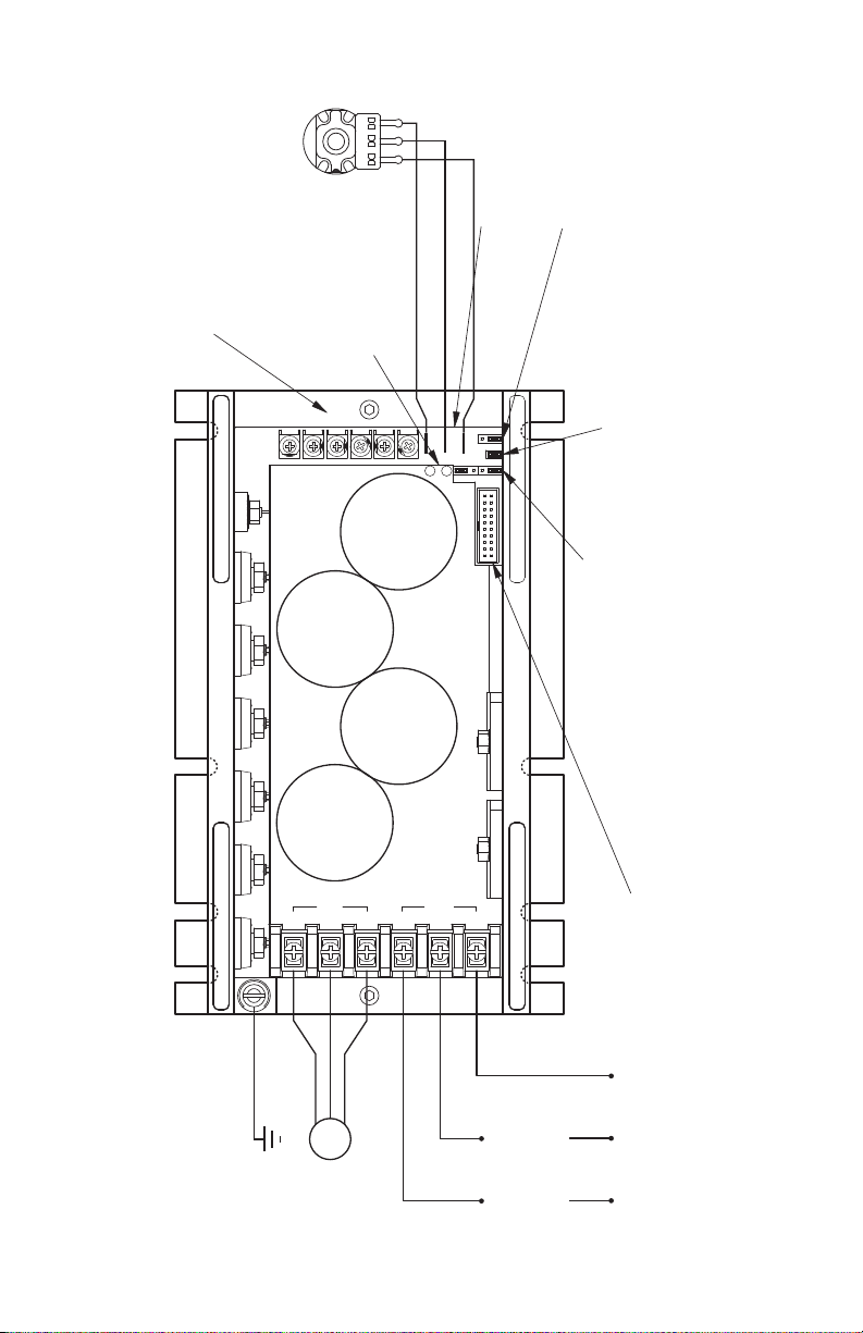
3 D5S -1 Layout . . . . . . . . . . . . . . . . . . . . . . . . . . . . . . . . . . . . . . . . . . . . . . . . . . . . . . . . . . . . . . . . 12
4 Mechanical Specifications and Drive Layout . . . . . . . . . . . . . . . . . . . . . . . . . . . . . . . . . . . . . . . . . . 13
5 Expanded View of Jumpers and Trimpots . . . . . . . . . . . . . . . . . . . . . . . . . . . . . . . . . . . . . . . . . . . 14
6 AC Line nput, Motor, and Ground Connections . . . . . . . . . . . . . . . . . . . . . . . . . . . . . . . . . . . . . . . 16
7 Catalog Nos. D5202-CO, D5203-CO Main Speed Potentiometer Connection . . . . . . . . . . . . . . . 16
8 Unidirectional Main Speed Potentiometer and Forward-Stop-Reverse Switch Connections . . . . . . 17
9 Bidirectional Main Speed Potentiometer Connection . . . . . . . . . . . . . . . . . . . . . . . . . . . . . . . . . . . 17
10 Catalog Nos. D5202-CO, D5203-CO Voltage Following Signal nput Connection . . . . . . . . . . . . . 17
11 Catalog Nos. D5401-CO, D5402-CO, D5403-CO, D5405-CO
Voltage Following Signal nput Connection . . . . . . . . . . . . . . . . . . . . . . . . . . . . . . . . . . . . . . . . . . . 18
12 Catalog Nos. D5401-CO, D5402-CO, D5403-CO, D5405-CO
Current Following Signal nput Connection . . . . . . . . . . . . . . . . . . . . . . . . . . . . . . . . . . . . . . . . . . . 18
13 Manual Start Switch Connection . . . . . . . . . . . . . . . . . . . . . . . . . . . . . . . . . . . . . . . . . . . . . . . . . . 18
14 Forward-Stop-Reverse Switch Connection . . . . . . . . . . . . . . . . . . . . . . . . . . . . . . . . . . . . . . . . . . . 19
15 Form “C” Contact or Relay Forward-Stop-Reverse Connection . . . . . . . . . . . . . . . . . . . . . . . . . . . 19
16 Open Collector Forward-Stop-Reverse Connection . . . . . . . . . . . . . . . . . . . . . . . . . . . . . . . . . . . . 19
17 Enable Switch Connection . . . . . . . . . . . . . . . . . . . . . . . . . . . . . . . . . . . . . . . . . . . . . . . . . . . . . . . 20
18 Run/Fault Relay Connection . . . . . . . . . . . . . . . . . . . . . . . . . . . . . . . . . . . . . . . . . . . . . . . . . . . . . . 20
19 Run/Fault Relay Output Contact Selection . . . . . . . . . . . . . . . . . . . . . . . . . . . . . . . . . . . . . . . . . . . 20
ii

TABLE OF CONTENTS (Continued)
Figures Page
20 60 Hz and 50 Hz Motor Selection . . . . . . . . . . . . . . . . . . . . . . . . . . . . . . . . . . . . . . . . . . . . . . . . . 21
21 Available Torque vs. Output Frequency . . . . . . . . . . . . . . . . . . . . . . . . . . . . . . . . . . . . . . . . . . . . . . 21
22 120 Hz and 100 Hz Drive Output Frequency Selection . . . . . . . . . . . . . . . . . . . . . . . . . . . . . . . . . . 21
23 Automatic Start . . . . . . . . . . . . . . . . . . . . . . . . . . . . . . . . . . . . . . . . . . . . . . . . . . . . . . . . . . . . . . . 21
24 Catalog Nos. D5202-CO, D5203-CO, Forward/Reverse Speed Selection . . . . . . . . . . . . . . . . . . 22
25 Catalog Nos. D5202-CO, D5203-CO Minimum Speed Trimpot Range . . . . . . . . . . . . . . . . . . . . 22
26 Catalog Nos. D5401-CO, D5402-CO, D5403-CO, D5405-CO Offset Trimpot . . . . . . . . . . . . . . . 22
27 Catalog Nos. D5202-CO, D5203-CO Maximum Speed Trimpot Range . . . . . . . . . . . . . . . . . . . . 23
28 Catalog Nos. D5401-CO, D5402-CO, D5403-CO, D5405-CO Maximum Speed Trimpot . . . . . . 23
29 Acceleration Trimpot Range All Models . . . . . . . . . . . . . . . . . . . . . . . . . . . . . . . . . . . . . . . . . . . . . . 23
30 Deceleration Trimpot Range All Models . . . . . . . . . . . . . . . . . . . . . . . . . . . . . . . . . . . . . . . . . . . . . 23
31 Slip Compensation Trimpot Range All Models . . . . . . . . . . . . . . . . . . . . . . . . . . . . . . . . . . . . . . . . 24
32 Boost Trimpot Range All Models . . . . . . . . . . . . . . . . . . . . . . . . . . . . . . . . . . . . . . . . . . . . . . . . . . 24
33 Catalog No. D5202-CO CL Trimpot Range . . . . . . . . . . . . . . . . . . . . . . . . . . . . . . . . . . . . . . . . . . 25
34 Catalog No. D5203-CO CL Trimpot Range . . . . . . . . . . . . . . . . . . . . . . . . . . . . . . . . . . . . . . . . . . 25
35 Catalog No. D5401-CO CL Trimpot Range . . . . . . . . . . . . . . . . . . . . . . . . . . . . . . . . . . . . . . . . . . 25
36 Catalog No. C5402-CO CL Trimpot Range . . . . . . . . . . . . . . . . . . . . . . . . . . . . . . . . . . . . . . . . . . 25
37 Catalog No. D5403-CO CL Trimpot Range . . . . . . . . . . . . . . . . . . . . . . . . . . . . . . . . . . . . . . . . . . 25
38 Catalog No. D5405-CO CL Trimpot Range . . . . . . . . . . . . . . . . . . . . . . . . . . . . . . . . . . . . . . . . . . 25
39 Maximum Allowed Motor Torque vs. Speed . . . . . . . . . . . . . . . . . . . . . . . . . . . . . . . . . . . . . . . . . . 26
40 Open Ventilated Motor with External Cooling . . . . . . . . . . . . . . . . . . . . . . . . . . . . . . . . . . . . . . . . . 26
iii

4
1 INTRODUCTION
Thank you for purchasing the Series 5 Adjustable Frequency Drive. This drive is UL Listed for
US and Canada, CE and is RoHS Compliant.
The Series 5 Adjustable Frequency Drives provide variable speed control for standard 3-phase
AC induction motors from 2 thru 5 HP1. This manual covers models with single-phase and 3-
phase AC line input. The sine wave coded Pulse Width Modulated (PWM) output operates at a
carrier frequency of 16 kHz, which provides high motor efficiency and low noise. Adjustable
linear acceleration and deceleration are provided, making the drive suitable for soft-start appli-
cations.
Adjusting the drive for a specific application is accomplished with selectable jumpers and trim-
pots. However, for most applications no adjustments are necessary.
Main features include adjustable RMS Current Limit and 2t Motor Overload Protection*. n
addition, Adjustable Slip Compensation with Static Auto-Tune and Boost provides high torque
and excellent load regulation over a wide speed range. Power Start™ delivers over 200%
motor torque to ensure startup of high frictional loads. Electronic nrush Current Limit (E CL™)
eliminates harmful AC line inrush current. The drive is suitable for machine or variable torque
(HVAC) applications.
A Signal solator (built-in on Catalog Nos. D5401-CO, D5402-CO, D5403-CO, D5405-CO
and optional on Catalog Nos. D5202-CO, D5203-CO) can be used for unidirectional or bidi-
rectional speed control and accepts voltage and current signal input.
This product complies with all CE directives pertinent at the time of manufacture.
Contact your local Baldor District Office for Declaration of Conformity.
Feature Description
Simple to Operate Trimpots and jumpers are factory set for most applications.
Industry Standard Mounting The drive has industry standard mounting dimensions.
Diagnostic EDs Power on (PWR, IPWR*) and drive status (ST). *On models with ID5SI-1
Built-In Cooling Fan Standard on Catalog Nos. ID5203-CO and ID5405-CO
Jumper Selections of Drive Output
Frequency Increases the motor speed up to two times the rated RPM.
Finger-safe cover Meets IP-20 standard.
TABLE 1 – STA DARD FEATURES
Feature Description
Power Start™ Provides more than 200% starting torque which ensures startup of high
frictional loads.
Slip Compensation with
Static Auto-Tune and Boost Provides excellent load regulation over a wide speed range.
Speed Range 60:1
TABLE 2 – PERFORMA CE FEATURES
* UL approved as an electronic overload protector for motors.
(1) See Section 8, paragraph 8.1 for recommendations on motor type.

5
Feature Description
Motor Overload (I2t) with RMS Current imit Provides motor overload protection which prevents motor burnout and eliminates
nuisance trips. U approved as an electronic overload protector for motors.
Electronic Inrush Current imit (EIC ™) Eliminates harmful inrush AC line current during startup.
Short Circuit Prevents drive failure if a short circuit occurs at the motor (phase-to-phase).
Regeneration Eliminates nuisance tripping due to high bus overvoltage caused by rapid deceleration
of high inertial loads.
Undervoltage and Overvoltage Shuts down the drive if the AC line input voltage is outside the operating range.
MOV input transient suppression Prevents failure of power devices caused by voltage spikes in the AC line.
Microcontroller Self Monitoring and Auto-Reboot.
TABLE 3 – PROTECTIO FEATURES
Trimpot
Minimum Speed (MIN) Sets the minimum motor speed.
Offset (OFFSET) Sets the minimum motor speed.
Maximum Speed (MAX) Sets the maximum motor speed.
Acceleration (ACC) Sets the motor acceleration time (time to reach full speed).
Deceleration (DEC/B) Sets the motor deceleration time (time to reach zero speed).
Slip Compensation (COMP) Maintains set motor speed under varying loads.
Boost (DEC/B) Sets the Volts/Hz Curve for 50 Hz motors to obtain maximum performance.
Current imit (C ) Sets the current limit and limits the maximum current (torque) to the motor.
TABLE 4 – TRIMPOT ADJUSTME TS
Accessory Description
Signal Isolator and Run/Fault Relay
(Catalog No. ID5SI-1)
Provides isolation between a non-isolated signal voltage (0 to ±25 Volts DC)
or current source (4 – 20 mA DC) and the drive. Mounts on the end of the drive. This
option is built-in on Catalog Nos. ID5401-CO, ID5402-CO, ID5403-CO, ID5405-CO.
TABLE 5 – OPTIO AL ACCESSORY
TABLE 6 – ELECTRICAL RATI GS*
Catalog
o.
AC Line Input Fuse or
Circuit
Breaker
Rating
(Amps)
Drive Output et Wt.
ominal
Volts AC
(50/60 Hz)
Phase
(φ)
Maximum
Current
(Amps AC)
Output
Voltage Range
(Volts AC)
Maximum
Continuous
Load Current
(RMS mps/Phase)
Maximum
Horsepower
(HP (kW)) Lbs. kg
ID5202-CO 208/230 1 17.0 20 0 – 230 6.7 2 (1.5) 4.1 1.9
3 8.0 10
ID5203-CO1208/230 3 10.8 15 0 – 230 9.0 3 (2.25) 4.6 2.1
ID5401-CO 400/460 3 2.4 5 0 – 400/460 2.0 1 (.75) 4.1 1.9
ID5402-CO 400/460 3 3.9 5 0 – 400/460 3.3 2 (1.5) 4.1 1.9
ID5403-CO2400/460 3 5.3 10 0 – 400/460 4.6 3 (2.25) 4.1 1.9
ID5405-CO1,2 400/460 3 9.6 15 0 – 400/460 8.3 5 (3.75) 4.6 2.1
Notes: 1. Catalog Nos. ID5203-CO, ID5405-CO contain built-in cooling fan. 2. Catalog Nos. ID5401-CO, ID5402-CO, ID5403-CO, ID5405-CO are
rated 0 – 400 Volts AC for 50 Hz motor operation and 0 – 460 Volts AC for 60 Hz motor operation.
*All models contain a erminal Block for AC line and motor connections. he Signal Isolator and Run/Fault Relay is standard on Catalog Nos.
ID5401-CO, ID5402-CO, ID5403-CO, ID5405-CO and optional on Catalog Nos. ID5202-CO, ID5203-CO.

6
TABLE 7 – GE ERAL PERFORMA CE SPECIFICATIO S
Notes: 1. Catalog Nos. ID5202-CO, ID5203-CO: if a non-isolated signal is used, or if using 0 to ±25 Volts DC or 4 – 20 mA DC signal input,
install the ID5SI-1 Signal Isolator. Catalog Nos. ID5401-CO, ID5402-CO, ID5403-CO, ID5405-CO contain built-in signal isolation. 2. Allows the
motor to operate up to two times the rated RPM. Constant motor horsepower will result when operating the drive in the “X2” mode above the
motor rated frequency. 3. Dependent on motor performance. 4. Do not operate the drive outside the specified AC line input voltage operating
range. 5. Catalog Nos. ID5403-CO, ID5405-CO.
Description Specification
Factory
Setting
208/230 Volt AC ine Input Voltage Operating Range (Volts AC) 208 (–15%) / 230 (+15%) —
400/460 Volt AC ine Input Voltage Operating Range (Volts AC) 380 (–15%) – 460 (+15%) —
Maximum oad (% Current Overload for 2 Minutes) 150 —
Carrier, Switching Frequency (kHz) 16, 8 —
Signal Following Input Voltage Range1(Volts DC)
Catalog Nos. ID5202-CO, ID5203-CO 0 – 5 —
Catalog Nos. ID5401-CO, ID5402-CO,
ID5403-CO, ID5405-CO 0 to ±25 0 to ±5
Signal Following Input Current Range1(mA DC) 4 – 20 —
Output Frequency Resolution (Bits, Hz) 10, .06 —
Minimum Speed Trimpot (MIN) Range (% Frequency Setting) 0 – 40 0
Maximum Speed Trimpot (MAX) Range (% Frequency Setting) 70 – 110 100
Acceleration Trimpot (ACC) and Deceleration Trimpot (DEC/B) Range (Seconds) .3 – 20 1.5
Boost Trimpot (DEC/B) Range (50 Hz Only) (Volts/Hz) 0 – 30 5
Slip Compensation Trimpot (COMP) Range at Drive Rating (Volts/Hz) 0 – 3 1.5
Current imit Trimpot (C ) Range (Amps AC)
Catalog No. ID5202-CO 4.0 – 12.5 10.7
Catalog No. ID5203-CO 5.5 – 17.0 14.4
Catalog No. ID5401-CO 1.3 – 3.8 3.2
Catalog No. ID5402-CO 2.1 – 6.2 5.3
Catalog No. ID5403-CO 3.0 – 8.5 7.4
Catalog No. ID5405-CO 5.0 – 15.5 13.3
Motor Frequency Setting (Hz) (Jumper J1) 50, 60 60
Output Frequency Multiplier (X1, X2) (Jumper J2)21, 2 1
Minimum Operating Frequency at Motor (Hz) 1—
Speed Range (Ratio) 60:1 —
Speed Regulation (30:1 Speed Range, 0 – Full oad) (% Base Speed)32.5 —
Overload Protector Trip Time for Stalled Motor (Seconds) 6—
AC ine Input Undervoltage/Overvoltage Trip Points for 208/230 Volt AC ine (±5%) (Volts AC)4151 – 282 —
AC ine Input Undervoltage/Overvoltage Trip Points for 400/460 Volt AC ine (±5%) (Volts AC)4302 – 567 —
Run/Fault Relay Output Contacts Rating5 (Amps at 30 Volts DC, 125 Volts AC, 250 Volts DC) 1, 0.5, 0.25 —
Operating Temperature Range (°C / °F) 0 – 45 / 32 – 113 —

SAFETY NOTICE
A Warning statement indicates a potentially hazardous situation which, if not avoided, could result
in injury or death.
A Caution statement indicates a potentially hazardous situation which, if not avoided, could result
in damage to property.
A Note indicates additional information that is not critical to the installation or operation.
WARNING! This equipment may contain voltages as high as 1000 volts! Electrical
shock can cause serious or fatal injury. Only qualified personnel should attempt the
start-up procedure or troubleshoot this equipment.
WARNING! Electrical shock can cause serious or fatal injury. Be sure that all power is
disconnected from drive before the finger-safe cover is removed. Removal of the
finger safe cover is required to make installation connections. Electrical shock can cause
serious or fatal injury if the finger-safe cover is removed and power is still applied.
WARNING! Electrical shock can cause serious or fatal injury. Verify there is no volt-
age phase-to-phase or phase-to-neutral at the AC Line Conductors before touching
the AC Input wires. Do not touch live wires, all power must be disconnected before proceeding.
WARNING! It is the responsibility of the equipment manufacturer and individual
installer to supply this Safety Warning to the ultimate end user of this product.
(SW/FSC 5/2005) Be sure to follow all instructions carefully. Fire and/or electrocution can result
due to improper use of this product.
WARNING! Do not use this drive in an explosive environment. An explosion can
cause serious or fatal injury. This drive is not explosion proof.
CAUTION!
Disconnect motor leads (U, V and W) from control before performing a “Leakage
Resistance” test on the motor. Failure to disconnect motor from the control may result in
extensive damage to the control. The control is tested at the factory for high voltage / leak-
age resistance as part of Underwriters Laboratories requirements.
CAUTION!
Suitable for use on a circuit capable of delivering not more than 5,000 RMS symmetrical
short circuit amperes listed here at rated voltage.
CAUTION!
Proper shielding, grounding, and filtering of this product can reduce the emission of radio
frequency interference (RFI) which may adversely affect sensitive electronic equipment.
7

8
2 QUIC -START INSTRUCTIONS
This procedure will help get your system up and running quickly and allows motor and control
operation to be verified.
WARNING! Electrical shock can cause serious or fatal injury. Be sure that all
power is disconnected from drive before the finger-safe cover is removed.
Removal of the finger safe cover is required to make installation connections. Electrical
shock can cause serious or fatal injury if the finger-safe cover is removed and power is
still applied.
WARNING! Electrical shock can cause serious or fatal injury. Only qualified
personnel should attempt installation, start-up procedure or to troubleshoot
this equipment.
2.1 Mount the drive. For instructions, see Section 3, on page 14
Note: Do not connect this drive to a Ground-Fault Circuit-Interrupter (GFCI). The WM
signal to the motor produces slightly more leakage than normal. This will cause GFCI to
trip. Filtering can reduce this leakage and GFCI trips.
2.2 Remove the finger-safe cover. For instructions, see Section 4, on page 14.
2.3 Connect AC power.
WARNING! Electrical shock can cause serious or fatal injury. Verify there
is no voltage phase-to-phase or phase-to-neutral at the AC Line
Conductors before touching the AC Input wires. Do not touch live wires, all power
must be disconnected before proceeding.
A main power disconnect installed between the AC power lines and the control is recom-
mended. Each AC Line wire that is not at neutral or ground potential must be protected.
For the recommended fuse ratings, see Table 6, on page 5. Also see Section 5.1, on
pages 15 and 16.
Connect the AC line wires to the control.
1. Catalog No. ID5202-CO: Connect the single-phase AC line input to terminals
“L1” and “L2”, or 3-phase AC line input to terminals “L1”, “L2” and “L3”.
See Figure 1, on page 10.
2. Catalog Nos. ID5203-CO, ID5401-CO, ID5402-CO, ID5403-CO, ID5405-CO:
Connect the 3-phase AC line input to terminals “L1”, “L2” and “L3”, See Figures 1
and 2, on pages 10 and 11. Also see Section 5.1, on pages 15 and 16.
2.4 Ground connection: Connect the ground (earth) conductor to the green ground screw.
See Figures 1 and 2, on pages 10 and 11.
2.5 Motor connection: Connect the motor wires to control terminals “U”, “V” and “W”. See
Figures 1 and 2, on pages 10 and 11. (Load reactors may be required for cable lengths
over 100 ft (30 m) – contact your local Baldor sales office).

9
2.6 Main speed potentiometer connection: For unidirectional speed operation: connect the
5 kΩpotentiometer to TB2 terminals “COM” (low), “S G” (wiper), “+5V ” (high).
1. Catalog Nos. ID5202-CO and ID5203-CO: Connect the 5 kΩpotentiometer to
Terminals “P1” (low), “P2” (wiper), “P3” (high).
2. Catalog Nos. ID5401-CO, ID5402-CO, ID5403-CO, ID5405-CO: Connect the 5 kΩ
potentiometer to Terminals “COM1” (low), “S G1” (wiper), “+5V” (high).
The Main Speed Potentiometer can also be connected for bidirectional speed operation.
See Section 5.4, on pages 16 and 17.
2.7 Signal Following: An analog signal input can be used to control motor speed instead of
the Main Speed Potentiometer. The drive output will linearly follow the analog signal input.
A Signal solator ( D5S -1) is built-in on Catalog Nos. D5401-CO, D5402-CO, D5403-
CO, D5405-CO and optional on Catalog Nos. D5202-CO, D5203-CO.
1. Catalog Nos. ID5202-CO, ID5203-CO: Connect the isolated* 0 – 5 Volt DC signal
input positive lead (+) to Terminal “P2” and the negative lead (–) to Terminal “P1”.
See Section 5.5, on pages 17 and 18.
*If a non-isolated signal is used, install the ID5SI-1 Signal Isolator. The ID5SI-1
accepts voltage (0 to ±25 Volts DC) or current (4 – 20 mA DC) signal inputs.
See Table 5, on page 5.
Note: For signal following operation, the Minimum Speed Trimpot (MIN) must be set
fully counterclockwise.
WARNING! The signal input must be isolated from the AC line. Earth
grounding signal wiring will damage the drive and void the warranty.
It is highly recommended that the ID5SI-1 Signal Isolator and Run/Fault Relay
be installed when using signal following.
2. Catalog Nos. ID5401-CO, ID5402-CO, ID5403-CO, ID5405-CO: Connect the volt-
age (0 to ±25 Volt DC) or current (4 – 20 mA DC) signal input to Terminals “S G1” (+)
and “COM1” (–) of Terminal Block TB1 on the D5S -1. For voltage following, be sure
Jumper J1 (on the D5S -1) is set to the “VOLT” position (factory setting). For current
following, set Jumper J1 (on the D5S -1) to the “CUR” position. A jumper must be
installed between Terminals “0V” and “FWD”, of Terminal Block TB1, in order for the
drive to operate.
2.8 60 Hz & 50 Hz Motor Operation (Jumpers J1 & J2 On the Lower PC Board): The
drive is factory set for 60 Hz motor operation (Jumper J1 set to the “60Hz” position and
Jumper J2 set to the “X1” position). For 50 Hz motor operation, set Jumper J1 to the
“50Hz” position and be sure Jumper J2 is set to the “X1” position. See Section 6.1, on
page 21.
2.9 Trimpot Settings: All trimpots have been factory set for most applications, as shown in
Figure 5, on page 14. Some applications require adjustments of the trimpots in order to
tailor the drive for a specific requirement. See Section 7, on pages 22 – 25.

10
CON1
CON2
CON3
X1 X2
J2
A/M
F- S - R
PWR
ST
P3P2
J1 P1
50/60Hz
MAXCLACCMIN DEC/B COMP
Main Speed Potentiometer (5 k)
see Section 5.4, on pages 16 & 17.
(Supplied) (Front View):
Adjustable Trimpots:
see Section 7, on pages 22 – 25.
Motor Connection:
see Section 5.1, on pages 15 & 16.
(Catalog No. ID5202-CO):
Single-Phase Connection
see Section 5.2, on page 16.
see Section 5.3, on page 16.
Ground (Earth):
Forward/Reverse Speed Selection:
see Section 5.7, on page 19.
see Section 5.8, on pages 19 & 20.
Enable Switch Connection,
Forward-Stop-Reverse Switch Connection:
see Section 6.3, on page 22.
for Accessories and Programming:
see Table 5, on page 5.
Communication Port
(Catalog No. ID5202-CO, ID5203-CO):
3-Phase Connection
see Section 5.1, on pages 15 & 16.
(Use L1, L2, L3)
(Use L1, L2)
see Section 6.1, on page 21.
For 60 Hz or 50 Hz Motor Operation:
the Rated Motor RPM:
For Two Times
Automatic Start:
Manual Start Switch Connection:
see Section 5.6, on pages 18 & 19.
see Section 6.2, on pages 21 & 22.
Voltage Following Signal Input
see Section 5.5, on pages 17 & 18.
in Lieu of Main Speed Potentiometer:
see Section 9, on page 28.
Diagnostic LEDs:
High
Wiper
Low
Motor
L3
LINE
W
MOTOR
UL2
AC
L1
VTB1
FIGURE 1 – CATALOG OS. ID5202-CO, ID5203-CO QUICK-START CO ECTIO DIAGRAM
(Shown without Finger-Safe Cover Insta ed)

11
Ground (Earth):
Motor Connection:
see Section 5.2, on page 16.
see Section 5.3, on page 16.
3-Phase Connection:
AC Line
Motor
L3
WL1
AC LINE
L2
VUTB1
MOTOR
50/60HzJ2
CON3
CON1
J1
X1 X2
A/M
CL MAX MIN ACC COMPDEC/B
TB1
TB2
see Section 5.1, on pages 15 & 16.
(Isolated Inputs)
Main Speed Potentiometer (Supplied),
Run/Fault Relay Output Contacts:
(Located Under Ribbon Cable)
Signal Input, and Direction Switch
or Contact Connections:
see Section 9, on page 28.
see Section 7, on pages 22 – 25.
Adjustable Trimpots:
Diagnostic LEDs
see Section 5.9, on page 20.
see Sections 5.4, 5.5, and 5.7
on pages 16 – 19.
see Section 5.6, on pages 18 & 19.
See Section 6.2, on pages 21 & 22.
Manual Start Switch Connection:
Automatic Start:
see Section 6.1, on page 21.
For Two Times the Rated Motor RPM:
see Section 6.1, on page 21.
For 60 Hz or 50 Hz Motor Operation:Communication Port
see Table 5, on page 5.
for Accessories and Programming:
FIGURE 2 – CATALOG OS. ID5401-CO, ID5402-CO, ID5403-CO, ID5404-CO QUICK-START CO ECTIO DIAGRAM
(Shown without Finger-Safe Cover Insta ed)

12
Signal Input, Direction Switch, and Main Speed Potentiometer connections.
Sets the drive for operation with a voltage or current input signal.
Sets the Run/Fault Relay Output Contacts for normally open or closed operation.
All jumpers are shown in factory set positions.
Run/Fault Relay Output Contacts connection.
Sets the operation of the Run/Fault Relay to Run or Fault.
Used to connect the Signal Isolator and Run/Fault Relay to the drive.
Sets the drive for operation with the optional Dynamic Brake Module.
MAXOFFSET
NDBM
J5
DBM
CON1
RUN
J4
FAULT
Power on LED.
Maximum Speed adjustment trimpot.
Signal Offset adjustment trimpot.
OV
PWR TB1
-5V+5V FWD REV COM1SIG1
VOLTCUR
TB2
K1 K2
NC
J2J1
NO
FIGURE 3 – ID5SI-1 LAYOUT
(ID5SI-1 is Bui t-In on Cata og Nos. ID5401-CO, ID5402-CO, ID5403-CO, ID5405-CO and Optiona on Cata og Nos. ID5202-CO, ID5203-CO)

13
a built-in cooling fan on this end.
31.8
12.7
0.5
(8 Places)
5.1
0.2
(Catalog Nos. ID5401-CO, ID5402-CO, ID5403-CO, ID5405-CO)
217
Catalog Nos. ID5203-CO, ID5405-CO contain
76.2
1.25
3.00
178
(ID5202-CO, ID5203-CO)
191
7.00
7.50
8.55
(optional on Catalog Nos. ID5202-CO, ID5203-CO).
ID5401-CO, ID5402-CO, ID5403-CO, ID5405-CO
Signal Isolator and Run/Fault Relay is standard on Catalog Nos.
4.00
102
119
99.0
3.90
4.70
contain a built-in cooling fan.
Finger-Safe Cover Retaining Clips
Catalog Nos. ID5203-CO, ID5405-CO
113
Catalog No. ID5202-CO, ID5203-CO:
110
Catalog Nos. ID5401-CO, ID5402-CO, ID5403-CO:
4.35
Maximum Height
4.45
4.15
105
See
Chart
L3
WL1
AC LINE
L2
VUTB1
MOTOR
50/60HzJ2
CON3
CON1
J1
X1 X2
A/M
CL MAX MIN ACC COMPDEC/B
TB1
TB2
FIGURE 4 – MECHA ICAL SPECIFICATIO S (I CHES/mm) & DRIVE LAYOUT
(Top View Shown without Finger-Safe Cover Insta ed) (Side View Shown with Finger-Safe Cover Insta ed)
(See Figure 5, On Page 14, for Expanded View of Jumpers and Trimpots)

14
3 MOUNTING INSTRUCTIONS
WARNING! Do not use this drive in an explosive environment. An explosion
can cause serious or fatal injury. This drive is not explosion proof.
3.1 Mounting the drive: This drive must be mounted in an enclosure. Avoid extreme
hazardous locations where physical damage to the drive can occur due to moisture,
metal chips, dust, and other contamination, including corrosive atmosphere that may be
harmful. The enclosure must allow for proper heat dissipation so that the ambient
temperature does not exceed 45 °C (113 °F). Leave at least 2” of clearance between the
top and bottom of the drive and the enclosure to allow for AC line, motor connection,
and other connections that are required. See Figure 4, on page 13.
Catalog Nos. ID5203-CO, ID5405-CO: When mounting the drive vertically, the cooling
fan must be on top.
3.2 Mounting The Main Speed Potentiometer: When mounting the Main Speed
Potentiometer, be sure to install the insulating disc between the potentiometer and the
panel. The Main Speed Potentiometer connects to Terminals “P1”, “P2”, “P3” on catalog
Nos. D5202-CO, D5203-CO and to Terminal Block TB1 (on D5S -1) on Catalog Nos.
D5401-CO, D5402-CO, D5403-CO, D5405-CO. See Section 5.4, on page 16.
4 FINGER-SAFE COVER
The drive is designed with an P-20 finger-safe cover to protect against accidental contact with
high voltage.
WARNING! Electrical shock can cause serious or fatal injury. Be sure that all
power is disconnected from drive before the finger-safe cover is removed.
Removal of the finger safe cover is required to make installation connections. Electrical
shock can cause serious or fatal injury if the finger-safe cover is removed and power is
still applied.
4.1 Removing the finger-safe cover: The finger-safe cover will have to be removed before
making electrical connections within the drive or setting selectable jumpers. All trimpots
can be adjusted with the finger-safe cover installed. Note the orientation of the finger-safe
cover before removing it.
Selectable Jumpers
A/M
CON2
CON1
J2 50/60Hz
CON3
J1X2X1 P1
F- S - R
PWR
P3P2
ST
Diagnostic LEDs
Main Speed Potentiometer
and Signal Input Terminals
MINCLMAX ACCDEC/B COMP
Adjustable Trimpots
FIGURE 5 – EXPA DED VIEW OF JUMPERS A D TRIMPOTS

15
To remove the finger-safe cover, gently lift up on the four retainer clips until the cover dis-
engages from the heat sink base. See Figure 4, on page 13.
4.2 Installing the finger-safe cover: To install the finger-safe cover, be sure to properly align
the retainer clips. Gently push the finger-safe cover until the retainer clips are fully
engaged with the heat sink base.
5 ELECTRICAL CONNECTIONS INSTRUCTIONS
WARNING! Electrical shock can cause serious or fatal injury. Be sure that all
power is disconnected from drive before the finger-safe cover is removed.
Removal of the finger safe cover is required to make installation connections. Electrical
shock can cause serious or fatal injury if the finger-safe cover is removed and power is
still applied.
Note: Electrical noise can be induced in unshielded wires that run parallel to each other. To
avoid erratic operation, it is important to separately route the AC line wires, motor wires, motor
feedback wires, start/stop contact wires, or any other signal wires. Each set of wires must be
enclosed in a separate conduit or shielded cable bundle for all signal wires over 12” (30 cm).
Do not bundle motor wires from multiple drives in the same conduit. The shield should be
earth grounded on the drive side only.
5.1 AC Line Connection:
WARNING! Electrical shock can cause serious or fatal injury. Verify there
is no voltage phase-to-phase or phase-to-neutral at the AC Line
Conductors before touching the AC Input wires. Do not touch live wires, all power
must be disconnected before proceeding.
A main power disconnect installed between the AC power lines and the control is recom-
mended and is required by most electrical codes. This provides a fail safe method to dis-
connect power to the drive. Electrical codes require that suitable branch circuit protection
be installed in each power conductor. Each AC Line wire that is not at neutral or ground
potential must be protected. For the recommended fuse ratings, see Table 6, on page 5.
AC Line Fuse: This drive does not contain AC line fuses. Most electrical codes require
that each ungrounded wire contain circuit protection. Do not fuse neutral or grounded
connections. t is recommended to install a fuse (Littelfuse 312/314, Buss ABC, or
Terminal Block
Maximum
Wire Size (Cu)
Recommended
Tightening Torque
Designation Description Location AWG mm2in-lbs kg-cm
TB1 AC ine Input and Motor Drive’s Upper PC Board 12 3.3 12 14
TB1** Signal Input, Direction Switch,
and Main Speed Potentiometer ID5SI-1*** 16 1.3 3.5 4
TB2** Run/Fault Relay Output Contacts ID5SI-1*** 16 1.3 3.5 4
TABLE 8 – TERMI AL BLOCK WIRE A D TIGHTE I G TORQUE SPECIFICATIO S
*Catalog Nos. ID5202-CO, ID5203-CO contain quick-connect terminals for signal input. Connectors are provided for wiring of Direction
Switch and Manual Start Switch. **Catalog Nos. ID5401-CO, ID5402-CO, ID5403-CO, ID5405-CO only. *** ID5SI-1 Signal Isolator and
Run/Fault Relay is standard on Models Catalog Nos. ID5401-CO, ID5402-CO, ID5403-CO, ID5405-CO and optional on Catalog
Nos. ID5202-CO, ID5203-CO.

16
equivalent) or a circuit breaker
(Square D QUO, or equivalent) in
series with each ungrounded wire.
For the recommended fuse size,
see Table 6, on page 5. Connect
the drive in accordance with the
National Electrical Code require-
ments and other local codes that
may apply to the application.
Connect the AC line wires to the
control.
1. Catalog No ID5202-CO:
Connect the single-phase AC
line input to terminals “L1” and
“L2” or 3-phase AC line input to
terminals “L1”, “L2” and “L3”.
See Figure 6.
2. For Catalog Nos. ID5203-CO,
ID5401-CO, ID5402-CO,
ID5403-CO and ID5405-CO
(3-phase): Connect the
single-phase AC line input to
Terminals “L1”, “L2”, “L3”. See Figure 6.
5.2 Ground Connection: Connect the
ground wire (earth) to the green ground
screw. The ground screw is located on
the heat sink. See Figure 6.
5.3 Motor Connection: Connect the motor
wires to Terminals “U”, “V” and “W”. The
terminals are located on the upper PC
board. See Figure 6. Motor cable length
should not exceed 100 ft. (30 m) –
special reactors may be required. Do not
fuse motor leads.
5.4 Main Speed Potentiometer
Connection: A 5 kΩMain Speed
Potentiometer is provided.
WARNING! Do not earth ground any Main Speed Potentiometer
terminals.
Note: When mounting the Main Speed otentiometer, be sure to install the insulating
disc (supplied) between the potentiometer and the panel.
1. Catalog Nos. ID5202-CO, ID5203-CO: Connect the Main Speed Potentiometer to
Terminals “P1” (low), “P2” (wiper), “P3” (high). The terminals are located on the lower
PC board. See Figure 7.
Wiper
Low
High
P1
(Supplied) (Front View)
Main Speed Potentiometer
P3P2
FIGURE 7 – CATALOG OS. ID5202-CO, ID5203-CO
MAI SPEED POTE TIOMETER CO ECTIO
(Unidirectional Operation)
Ground (Earth)
(Catalog No. ID5202-CO)
Single-Phase Connection
(Use L1, L2)
Motor Connection
ID5401-CO, ID5402-CO, ID5403-CO, ID5405-CO).
3-Phase Connection (Use L1, L2, L3) (Catalog Nos. ID5202-CO, ID5203-CO,
L3
Motor
MOTOR AC LINE
L2L1
WTB1 VU
FIGURE 6 – AC LI E I PUT, MOTOR
& GROU D CO ECTIO S

17
2. Catalog Nos. ID5401-CO,
ID5402-CO, ID5403-CO,
ID5405-CO: Connect the
Main Speed Potentiometer
to Terminal Block TB1 on
the D5S -1.
Unidirectional Speed
Operation: Connect the
Main Speed Potentiometer
to Terminals “+5V” (high),
“S G1” (wiper), “COM1”
(low). Motor direction is
selected with a Forward-
Stop-Reverse Switch
connected to Terminals “0V”
(common of switch), “FWD”,
“REV”. See Figure 8. f a
Forward-Stop-Reverse
Switch is not used, a jumper
must be installed between
Terminals “0V” and “FWD”,
of Terminal Block TB1, in
order for the drive to
operate.
Bidirectional Speed
Operation: Connect the
Main Speed Potentiometer to
Terminals “+5V” (high), “S G1”
(wiper), “– 5V” (low). Terminals
“FWD”, “REV”, “COM1” must be
connected together. See Figure 9.
5.5 Signal Following Connections: The
drive output will linearly follow the analog
signal input.
Catalog Nos. ID5202-CO, ID5203-CO:
Connect the isolated* 0 – 5 Volt DC
signal input positive lead (+) to Terminal “P2” and the negative lead (–) to Terminal “P1”.
The terminals are located on the lower PC board. With external circuitry, a 0 – 10 Volt DC
analog signal can also be used. See Figure 10.
*If a non-isolated signal is used, install the ID5SI-1 Signal Isolator. The ID5SI-1 accepts volt-
age (0 to ±25 Volts DC) or current (4 – 20 mA DC) signal inputs. See Table 5, on page 5.
Note: For signal following operation, the Minimum Speed Trimpot (MIN) must be set fully
counterclockwise.
REV
High Stop
-5V
TB1
+5V 0V FWD
Forward
Wiper
Potentiometer
Main Speed
(5 k)
Low
Reverse
SIG1 COM1
ID5SI-1
TERMINAL
BLOCK
CUR VOLT
J1
FIGURE 8 – U IDIRECTIO AL MAI SPEED POTE TIOMETER
& FORWARD-STOP-REVERSE SWITCH CO ECTIO S
(Jumper J1 Installed in “VOLT” Position)
REV-5V
TB1
+5V 0V FWD SIG1 COM1
Main Speed
Potentiometer Wiper
(5 k) High Jumper
Low
Jumper
CUR VOLT
J1
ID5SI-1
TERMINAL
BLOCK
FIGURE 9 – BIDIRECTIO AL
MAI SPEED POTE TIOMETER CO ECTIO
(Terminals “FWD”, “REV”, “COM1” Connected)
(Jumper J1 Installed in “VOLT” Position)
FIGURE 10 – CATALOG OS. ID5202-CO, ID5203-CO
VOLTAGE FOLLOWI G SIG AL I PUT CO ECTIO
0 – 5 Volts DC (Isolated) 0 – 10 Volts DC (Isolated)
P1 P2 P3
0 - 5
Volts DC
+
-
V
P1 P2 P3
0 - 10
Volts DC
V
+
-
10k
10k

18
WARNING! The signal
input must be isolated
from the AC line. Earth grounding
signal connections will damage the
drive and void the warranty. It is
recommended that the ID5SI-1
Signal Isolator and Run/Fault Relay
be installed when using signal
following.
Catalog Nos. ID5401-CO, ID5402-
CO, ID5403-CO, ID5405-CO: The
D5S -1 is factory calibrated for 0 to
±5 Volt DC signal input. Connect the
voltage (0 to ±25 Volt DC) or current
(4 – 20 mA DC) signal input to
Terminals “S G1” (+) and “COM1” (–)
of Terminal Block TB1 on the
D5S -1. For voltage following, be
sure Jumper J1 (on the D5S -1) is set
to the “VOLT” position (factory set-
ting). For current following, set
Jumper J1 (on the D5S -1) to the
“CUR” position. See Figures 11 and
12. A jumper must be installed
between Terminals “0V” and “FWD”,
of Terminal Block TB1, in order for
the drive to operate.
Application Note: In the
Voltage Following Mode, the
input will accept a “+” and “–“
input voltage, which will run the
motor in the forward and
reverse direction.
Notes: 1. The MIN Trimpot
on Catalog Nos. ID5401-CO,
ID5402-CO, ID5403-CO,
ID5405-CO is not functional.
Use the OFFSET Trimpot on the ID5SI-1 to offset the signal input, as described in
Section 7.1, on page 22. 2. Do not use the MAX Trimpot on Catalog Nos. ID5401-CO,
ID5402-CO, ID5403-CO, ID5405-CO. Use the MAX Trimpot on the ID5SI-1 to scale the
signal input, as described in Section 7.2, on page 23.
5.6 Manual Start Switch Connection (CON1): The Manual Start Mode is used to manually
start the drive or restart the drive (reset) if a fault has occurred. To operate the drive in the
Manual Start Mode, remove the factory installed jumper on CON1 and install the 2-wire
connector (supplied). CON1 is located on the lower PC board. Connect CON1 to a
momentary switch or contact, as shown in Figure 13.
REV-5V
TB1
+5V 0V FWD SIG1 COM1
Jumper
0 to ±2.5 thru 0 to ±25
Volts DC
+
V
-
CUR VOLT
J1
ID5SI-1
TERMINAL
BLOCK
FIGURE 11 – CATALOG OS. ID5401-CO,
ID5402-CO ID5403-CO, ID5405-CO
VOLTAGE FOLLOWI G SIG AL I PUT CO ECTIO
(0 to ±25 Volts DC)
(Jumper J1 Installed in “VOLT” Position)
REV-5V
TB1
+5V 0V FWD SIG1 COM1
Jumper
+
-
4 - 20 mA DC
CUR VOLT
J1
ID5SI-1
TERMINAL
BLOCK
FIGURE 12 – CATALOG OS. ID5401-CO,
ID5402-CO ID5403-CO, ID5405-CO
CURRE T FOLLOWI G SIG AL I PUT CO ECTIO
(Jumper J1 Installed in “CUR” Position)
FIGURE 13 – MA UAL START SWITCH CO ECTIO
Jumper Removed
Connector Installed for
Manual Start Switch
CON1
A/M
Manual Start Switch
(Momentary Contacts)
(Push to Run)
White
Black
CON1

19
n the Manual Start Mode,
the drive will trip due to all
faults (Overvoltage,
Undervoltage, Short Circuit,
and 2t) and remain tripped
even when the fault is
cleared. To Start/Reset the
drive, the switch or contact
must be manually closed.
Also, the drive must be
restarted each time the AC
line is interrupted.
For Automatic Start, see Section
6.2, on pages 21 and 22.
Notes: 1. See Section 8.3, on page
27. Also see Section 9.2, on page
28. 2. The drive can be factory pro-
grammed for Run/Stop operation
with momentary contacts.
5.7 Forward-Stop-Reverse Switch
Connection (CON2): The drive can
operate using a Forward-Stop-
Reverse Switch, Contact, or Open
Collector.
1. Catalog Nos. ID5202-CO,
ID5203-CO: Remove the factory
installed jumper on CON2 and
install the 3-wire connector (sup-
plied). CON2 is located on the
lower PC board. Connect a
“maintained” switch or contact to
the 3-wire connector. See Figure 14. Also see Forward/Reverse Speed Selection, in
Section 6.3, on page 22.
f installing the D5S -1 Signal solator, See number 2.
Note: The drive can be factory programmed for momentary contact operation.
2. Catalog Nos. ID5401-CO, ID5402-CO, ID5403-CO, ID5405-CO: Connect the
Forward-Stop-Reverse Switch as shown in Figure 8, on page 17. f using Form “C”
Contact or Relay, connect the circuit as shown in Figure 15. f using Open Collector,
connect the circuit as shown in Figure 16.
5.8 Enable Switch Connection (CON2): The drive can be started and stopped with an
Enable Switch (close to run, open to stop). Remove the factory installed jumper on
CON2 and install the 3-wire connector (supplied). CON2 is located on the lower PC
board. Connect a “maintained” switch or contact to the 3-wire connector. See Figure 17,
on page 20.
REV-5V
TB1
+5V 0V FWD SIG1 COM1
Forward Reverse
ID5SI-1
TERMINAL
BLOCK
FIGURE 15 – FORM “C” CO TACT OR RELAY
FORWARD-STOP-REVERSE CO ECTIO
REV-5V
TB1
+5V 0V FWD SIG1 COM1
Forward Reverse
ID5SI-1
TERMINAL
BLOCK
FIGURE 16 – OPE COLLECTOR
FORWARD-STOP-REVERSE CO ECTIO
FIGURE 14 – FORWARD-STOP-REVERSE SWITCH CO ECTIO
Jumper Removed
Connector Installed for
Forward-Stop-Reverse Switch
CON2
F - S - R
Forward-Stop-Reverse
Black
White
CON2
Red
Stop
Forward
Reverse
Switch

20
For Forward Enable Operation, connect the switch to
the white and black wires. For Reverse Enable
Operation, connect the switch to the red and black
wires. When the switch is closed, the drive will run. When
the switch is opened, the drive will stop.
5.9 Run/Fault Relay: The Run/Fault Relay is built-in on
Catalog Nos. D5401-CO, D5402-CO, D5403-CO,
D5405-CO and optional on Catalog Nos. D5202-CO,
D5203-CO. The Run/Fault Relay Output Contacts are
located at TB2 of the D5S -1 and can be used
to turn on or off equipment or to signal a warn-
ing if the drive is put into the Stop Mode or a
fault has occurred. See Figure 18. Also see
Table 9.
For normally open contacts, set Jumper J2
(on the D5S -1) to the “NO” position. For
normally closed contacts, set Jumper J2
(on the D5S -1) to the “NC” position.
See Figure 19.
FIGURE 17 – E ABLE SWITCH CO ECTIO
Jumper Removed
Connector Installed for
Forward Enable Switch
Connector Installed for
Reverse Enable Switch
CON2
F- S - R
(Close to Run)
Re d * (Open to Stop)
Black
White
Enable Switch
CON2 Forward
(Close to Run)
Red
(Open to Stop)
Black
White*
Enable Switch
CON2
Reverse
*For Forward Enable Switch connection, the red wire is not used. For Reverse Enable Switch connection, the white
wire is not used. The unused wire must be insulated or it may be cut off at the connector.
FIGURE 19 – RU /FAULT RELAY
OUTPUT CO TACT SELECTIO
ormally Open Contacts ormally Closed Contacts
Jumper J2 Installed in
“ O” Position
(Factory Setting)
Jumper J2 Installed in
“ C” Position
J2
NC NO
J2
NC NO
K1 K2
TB2
Run/Fault Relay Output Contacts
FIGURE 18
RU /FAULT RELAY CO ECTIO
TABLE 9 – DRIVE OPERATI G CO DITIO A D RU /FAULT RELAY CO TACT STATUS
DRIVE
OPERATI G
CO DITIO DESCRIPTIO
RELAY CO TACT STATUS (TERMI ALS K1 A D K2 OF TB2)
RU RELAY OPERATIO
(Jumper J4 Installed in “RU ” Position)
(Factory Setting)
FAULT RELAY OPERATIO
(Jumper J4 Installed in “FAULT” Position)
JUMPER J2 I STALLED I
“ O” POSITIO
(Factory Setting)
JUMPER J2
I STALLED I
“ C” POSITIO
JUMPER J2 I STALLED I
“ O” POSITIO
(Factory Setting)
JUMPER J2 I STALLED I
“ C” POSITIO
Power Off Main Power
Disconnected Open Closed Open Closed
Run Mode* Normal
Drive Operation Closed Open Closed Open
Stop Mode* Selected by
Operator Open Closed Closed Open
Fault** Drive Tripped Open Closed Open Closed
*Run Mode or Stop Mode is selected using the Forward-Stop-Reverse Switch. ** Fault: Overload, I2t, Short Circuit, Undervoltage, and Overvoltage.
Other manuals for SERIES 5
1
This manual suits for next models
6
Table of contents
Other Baldor DC Drive manuals
Popular DC Drive manuals by other brands

Conner
Conner 800 MB Travan installation manual

JUNG ANTRIEBSTECHNIK U. AUTOMATION GMBH
JUNG ANTRIEBSTECHNIK U. AUTOMATION GMBH HighDynamic HA02-37 installation guide

Danfoss
Danfoss VLT HVAC Drive FC 100 Series Design guide

WEG
WEG CFW-11 Series Programming manual

Danfoss
Danfoss VLT HVAC FC 100 Service manual

ABB
ABB ACS 6000 user manual