Ballenger Motorsports AFR500v2 User manual

Ballenger Mo
torsports AFR500
v2
Manual Rev
1.
4
a
-
1
-
Ballenger Motorsports, Inc.
8052 Elm Drive, Ste G
Mechanicsville, VA 23111
Phone: (804) 915-7201
Fax: (804) 433-3825
www.bmotorsports.com
AFR500v2 Tuning Manual
Ballenger Mo
torsports AFR500
v2
Manual Rev
1.
4
a
-
2
-
1. Critical Product Notes
• Do calibrate your AFR500v2 in free air before first use!
• When powered, the oxygen sensor becomes very hot and will stay
very hot for some time after use. Take caution with this heated sensor
to avoid burns or ignition of flammable substances.
• Do not leave the sensor in the exhaust stream while disconnected
from the controller or unpowered. This will foul an oxygen sensor
rapidly.
• Do take extreme care when changing internal option jumpers in
AFR500v2 controller.
• Do not apply excessive voltage (more than 28V DC) to the harness.
• Do not allow the sensor to be dropped or be handled roughly; the
delicate ceramic internals may be damaged by mishandling.
• Do not modify the wiring harness.
• Do not run the wiring harness near hot or sharp objects. A short in
this harness could result in a fire.
• Do not use the wiring harness if it is damaged. Replace it.
• Do not expose the AFR500v2 to open weather conditions or water
as the enclosure is not fully sealed (contact us about sealing).
• Do not open or modify the oxygen sensor.
Please read this manual fully to understand the proper use of the
AFR500v2. Misuse, mishandling and a lack of understanding may
cause premature failure or inaccurate readings. We do not take
responsibility for and cannot warranty the AFR500v2 kit in cases of
improper use or improper applications.
Ballenger Motorsports does not accept any responsibility for incurred
damage as a result of using the AFR500v2.

Ballenger Mo
torsports AFR500
v2
Manual Rev
1.
4
a
-
3
-
Table of Contents
1. Critical Product Notes ......................................................................2
2. Introduction ......................................................................................3
3. New features in the AFR500v2........................................................3
4. Kit Contents......................................................................................4
5. Functional Description .....................................................................4
6. Wiring Installation............................................................................5
6a. Dyno Specific Wiring & Grounding ..............................................6
7. Setting & Explanation of Options ....................................................7
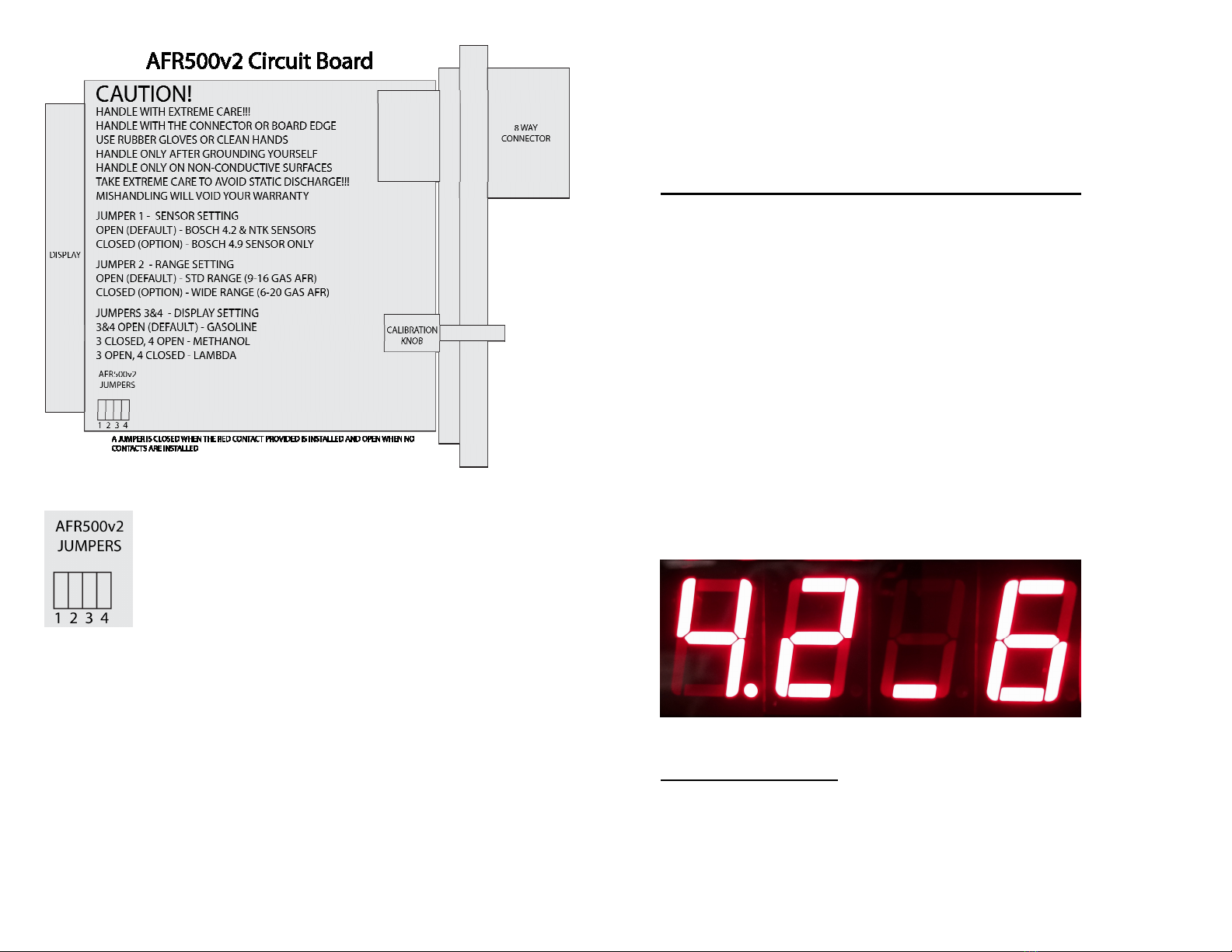
8. How to set Jumper Configuration Options.......................................8
9. Display of Configuration Options (Check Settings) ......................10
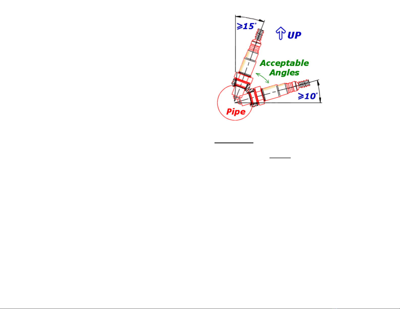
10. Sensor Installation ........................................................................10
11. Calibration....................................................................................12
12. Analog Output ..............................................................................13
13. Analog Output Values..................................................................13
14. Display .........................................................................................14
15. Compatible Fuels..........................................................................14
16. Troubleshooting ...........................................................................14
17. How to maximize sensor life........................................................16
18. Spare Parts....................................................................................17
2. Introduction
The AFR500v2 is a precision oxygen concentration measurement
system. Unlike conventional oxygen sensors which only work near a
stoichiometric ratio (14.64:1 or 1.00λ), the AFR500v2 uses unique
wideband technology to sense gasoline air-fuel ratios in the range of
9:1-16:1 (0.62-1.10 λ[lambda], 4:1-7.1:1 Methanol) or 6:1-20:1
(0.411-1.373 λ, 2.66:1-8.88:1 Methanol). The system is capable of
working with most fuel types.
3. New features in the AFR500v2
The AFR500v2 is a major iteration on the AFR500. All features &
functions of the original AFR500 remain intact with the added
improvements below:
Ballenger Mo
torsports AFR500
v2
Manual Rev
1.
4
a
-
4
-
• Lambda & Methanol AFR display options
• Extreme Range option for FI methanol & laboratory applications
• (0.411-1.373 Lambda)
• (6-20 Gas AFR)
• (2.66-8.88 Methanol AFR)
• Increased display speed
• Bosch LSU 4.9 option
• Faster analog output
• All harnesses, control units, accessories, etc (except the LSU 4.9)
are backwards and forwards compatible
• Options are selectable at any time via internal jumpers
• NTK Calibration grade sensor highly recommended for low AFR
methanol applications
4. Kit Contents
• AFR500v2 Controller
• Wideband oxygen sensor (Bosch LSU 4.2, 4.9, or NTK Sensors)
• 13ft (standard), 7ft, or 24ft wiring harness
• AFR500v2 Tuning Manual
• Weld-in sensor bung
• Screw-in sensor plug
• Adhesive backed hook & loop pair
• 3 red configuration jumper contacts
5. Functional Description
The wideband sensor infers an air fuel ratio relative to the
stoichiometric (chemically balanced) air fuel ratio by balancing the
amount of oxygen pumped in or out of a measurement chamber. As
the exhaust gasses get richer or leaner, the amount of oxygen that
must be pumped in or out to maintain a stoichiometric air fuel ratio in
the measurement chamber varies in proportion to the air fuel ratio. By
measuring the current required to pump the oxygen in or out, the air
fuel ratio (lambda) can be estimated. Note that the measured air fuel
ratio is the output from the AFR500v2 pumping current controller and
not a signal that comes directly from the sensor. Wideband sensors

Ballenger Mo
torsports AFR500
v2
Manual Rev
1.
4
a
-
5
-
DO NOT output a voltage that can be directly measured as
conventional oxygen sensors do.
6. Wiring Installation
Black – Primary Ground
Red – Primary Power
Orange, White, Blue, Pink – Sensor Specific wires
Yellow – Analog Output
Black with white stripe – Analog Ground
The Yellow & Black/White Analog wires are unterminated and
wrapped under tape in the harness. Follow these wires from the
AFR500v2 connector and remove the tape holding the ends in place.
Once exposed, the analog wires may be used as-is or extended with
high quality butt connectors to another device.
A fused, red wire with a #8 spade connection is provided to connect
to a switched power source. This power source should be capable of
supplying 3A and should operate between 11v – 28v. Ideally this
source will be above 13v during operation. Any extensions of main
power should be 16AWG or larger with a high quality butt connection
and properly validated crimp joint.
A good, noise free ground is critical for best performance. A
black wire with a #8 spade connection is provided to connect to a
reliable ground source, ideally the battery. If the analog output is
used with an onboard logger or ECU, the analog ground and main
ground should be connected to the same location to avoid a ground
loop or offset.
If the analog output is used with a tuning device such as an HP
Tuners, EFI Live, or similar system, the analog ground should be
connected to the tuning device’s analog ground. In cases where the
analog ground is connected to a tuning device, ECU, or logger, the
main ground should be connected to the battery or chassis. Any
Ballenger Mo
torsports AFR500
v2
Manual Rev
1.
4
a
-
6
-
extensions of the main ground should be 14AWG or larger with a
high quality butt connection with both AFR500v2 main ground wires
and a properly validated crimp joint.
Avoid high temperature, high vibration, sharp objects and ignition
components when routing the wiring harness.
If you wish to install the AFR500v2 across a firewall, it is relatively
simple to de-pin the Deutsch connector at the AFR500v2 controller. If
the numbers on the back of the Deutsch connector are unreadable,
TAKE PICTURES and NOTE THE WIRING POSITIONS. The
orange wedgelock can be removed from the front of the connector and
the terminals de-pinned with a small screwdriver. Be sure power is
disconnected when doing this and take care not to bend any wires.
The Deutsch wiring pinout follows:
1. Orange wire
2. Red wire
3. Yellow wire
4. Black wire with white stripe
5. Blue wire
6. White wire
7. Pink wire
8. Black wire
6a. Dyno Specific Wiring & Grounding
Improper grounding will cause serious problems, including damage to
your AFR500v2. The dyno frame or chassis must be connected to
building electrical ground in accordance with National Electrical
Code (NEC) requirements.
Vehicles operated on a chassis dyno will generate considerable
electrostatic charge. The vehicle must be grounded to the dyno frame
while in operation. You can use a length of 16 AWG wire with one
end secured to the dyno frame and the other end equipped with a
heavy duty alligator clip that is attached to the vehicle frame or other
vehicle ground point. Failure to ground the vehicle will lead to

Ballenger Mo
torsports AFR500
v2
Manual Rev
1.
4
a
-
7
-
electrostatic discharge (ESD) across the wideband sensor damaging
the sensor and AFR500v2.
If you connect the main ground of an AFR500v2 to a vehicle and the
analog ground of an AFR500v2 to the analog input of a dyno
controller/logger without a dedicated ground path, you will pass this
voltage difference through the AFR500v2 and its wideband sensor.
This will skew your readings as well as damage the sensor &
controller.
7. Setting & Explanation of Options
Three new options have been added to the AFR500v2 which require
the installation of red jumper contacts (provided).
The first option is Bosch LSU 4.9 sensor capability. As shipped
(unless otherwise specified), this is set for the Bosch LSU 4.2 & NTK
Sensors. You must install a red jumper to enable LSU 4.9 ONLY
mode.
The second option is for fuel measurement range. As shipped (unless
otherwise specified), this is set for the Wideband (Standard) range of
9:1-16:1 for gasoline. Most customers should keep the standard range
setting. Only use the Extreme (FI Methanol/Lab) range setting if you
have a specific reason as increased range is traded for resolution. The
extreme range is 6:1-20:1 gasoline AFR. You must install a red
jumper to enable extreme range measurement.
The third option is for the display. The AFR500v2 can display
gasoline AFR, lambda, & methanol AFR. Today’s fuels are
increasingly complex with mixes and exotic fuel types. Some
customers are specifically familiar with methanol AFR rather than
gasoline AFR. We’ve added lambda as it handles fuel based
variations and is a better option than gasoline AFR for most modern
fuels. Methanol is exclusively for use with race alcohol / methanol
fuel. You must install a red jumper to enable lambda or methanol
display options.
Ballenger Mo
torsports AFR500
v2
Manual Rev
1.
4
a
-
8
-
8. How to set Jumper Configuration Options
See section 9 on how to check your configuration options, you do not
need to open the AFR500v2 to check your settings!
CAUTION!
HANDLE WITH EXTREME CARE!!!
HANDLE WITH THE CONNECTOR OR BOARD EDGE
USE RUBBER GLOVES OR CLEAN HANDS
HANDLE ONLY AFTER GROUNDING YOURSELF
HANDLE ONLY ON NON-CONDUCTIVE SURFACES
TAKE EXTREME CARE TO AVOID STATIC DISCHARGE!!!
MISHANDLING WILL VOID YOUR WARRANTY
Before removing the AFR500v2 circuit board, ground yourself and
plan a specific work zone that is nonconductive and stable. Do not
touch any components.
The AFR500v2 circuit board pulls out from its enclosure with the
removal of two external screws and the Deutsch connector. Once
removed, jumpers will be visible in the lower left corner of the circuit
board when looking in the orientation shown in Fig 1. The provided
jumpers are red and have long ergonomic handles to avoid touching
any board components directly. If a red contact jumper is installed,
then the circuit is closed. If no red contact jumper is installed, then
the circuit is open.

Ballenger Mo
torsports AFR500
v2
Manual Rev
1.
4
a
-
9
-
Fig 1. AFR500v2 Circuit Board when removed from case.
Fig 2. AFR500v2 Jumper Settings Closeup View
Jumper 1 - Sensor Configuration
No Jumper – Bosch LSU 4.2 & NTK Sensors
Jumpered – Bosch LSU 4.9 ONLY!
Jumper 2 - Range Setting
No Jumper – Wideband (Standard) Range (9-16 Gas AFR)
Jumpered – Extreme (FI Methanol/Lab) Range (6-20 Gas AFR)
Jumpers 3&4 – Display Setting
Ballenger Mo
torsports AFR500
v2
Manual Rev
1.
4
a
-
10
-
3&4 No Jumper – Gasoline AFR Display
3 Jumpered, 4 No Jumper – Methanol AFR Display
3 No Jumper, 4 Jumpered – Lambda Display
3 Jumpered, 4 Jumpered – No Function
9. Display of Configuration Options (Check Settings)
When power is applied, the AFR500v2 will display your
configuration options.
The first two digits on display during boot indicate Sensor
configuration.
4.2 Indicates LSU 4.2 / NTK Sensors
4.9 Indicates LSU 4.9 only
The third digit of display indicates range option.
Dash at button is std range, dash at top is extreme range.
The fourth digit of display indicates fuel displayed.
6 indicates gasoline
A indicates methanol
L indicates lambda
Fig 3. Example of default settings on start-up.
10. Sensor Installation

Ballenger Mo
torsports AFR500
v2
Manual Rev
1.
4
a
-
11
-
Oxygen sensors are sensitive to temperature, pressure and
contaminants. A non-ideal sensor installation may dramatically
reduce your sensor life.
Ensure that there are no leaks in the exhaust system as this will falsely
indicate lean or high air fuel ratio values. The sensor should be
installed upstream of any air-injection equipment.
The sensor should not be installed in a pressurized environment and
therefore should be installed downstream of any turbochargers or
similar systems causing exhaust pressure.
The sensor should be installed upstream of any emissions systems and
catalytic converters.
Typically, the oxygen sensor should be installed 1ft to 4ft from the
exhaust ports. A sensor that is too close will receive frequent thermal
variations, leading to a reduced sensor life. A sensor that is too far
away may run too cold and risk condensate leading to reduced sensor
life.
The sensor should be installed at least 10˚ above horizontal to avoid
condensation and water pooling in the sensing element. Ideally the
sensor is installed off vertical between the 10 and 2 clock positions
(see Fig 4).
The electrical connector should be installed to maximize strain relief
at the sensor and connector, to keep the connector clean and free of
contaminants, and to keep the plastic connector away from excessive
heat.
Ballenger Mo
torsports AFR500
v2
Manual Rev
1.
4
a
-
12
-
Fig 4. Minimum installation angle above horizontal
11. Calibration
Sensor calibration is a
critical
step in setting up your AFR500v2
wideband system. Follow the steps below to reliably calibrate your
AFR500v2:
1. Connect the wiring harness to the AFR500v2 controller and to
the oxygen sensor without power and ground. Hold the sensor
in FREE AIR by the wires or on a safe, non-reactive surface
that will not melt. Performing a calibration with the sensor in
the exhaust is unreliable even if the engine has been off for
days.
2. Connect power and ground to the AFR500v2. The sensor will
rapidly heat up. Take care not to touch this sensor directly!
3. Wait 10 minutes or more while the sensor saturates. The
longer, the better.
4. Turn the calibration knob until the AFR500v2 reads “CAL–”.
If it reads “Air_”, turn clockwise. If it reads “Airˉˉ ”, turn
counterclockwise. When the AFR500v2 reads “CAL–”, your
sensor calibration is complete.

Ballenger Mo
torsports AFR500
v2
Manual Rev
1.
4
a
-
13
-
5. Your AFR500 may read 16.00, Airˉˉ, Air_, or CAL– before
engine startup or when letting off the throttle of a fuel injected
vehicle, this is normal.
6. Recheck the sensor periodically. Sensor drift will depend on
use where a well tuned street vehicle will need rechecking less
often than a leaded fuel dragster.
7. Disconnect power from the AFR500v2 harness. Once the
sensor cools down, install the oxygen sensor. Take care, it
will be hot for a long time! Take care not to bump or knock
the calibration knob on the AFR500v2 until your next
calibration!
12. Analog Output
The AFR500v2 has a 0v to 5v linear voltage output where 0v is equal
to 9:1 air-fuel ratio for gasoline and 5v is equal to 16:1 air-fuel ratio
for gasoline. In extreme range mode, 0v is equal to 6:1 for gasoline
and 5v is equal to 20:1 for gasoline. Take care to wire the analog
output and ground. The main ground and analog ground should be
connected to the same location to avoid a ground loop or shift.
13. Analog Output Values
When set to Wideband (Standard) Range:
Gasoline AFR (9:1-16:1) = 9.00 + Vout x 1.400
Methanol AFR (4.00-7.10) = 4.00 + Vout x 0.62
Lambda (.618-1.098) = 0.618 + Vout x 0.096
When set to Extreme (FI Methanol/Lab) Range:
Gasoline AFR (6:1-20:1) = 6.00 + Vout x 2.800
Methanol AFR (2.66-8.88) = 2.66 + Vout x 1.244
Lambda (.411-1.373) = 0.411 + Vout x 0.1923
Ballenger Mo
torsports AFR500
v2
Manual Rev
1.
4
a
-
14
-
It is important to observe any analog offsets. Any analog input in a
logging system may suffer from a voltage offset, requiring that you
always check your analog values against a known reference. In the
case of the AFR500v2, there is a special provision for this.
During startup, the AFR500v2 will output 1 volt (10.4 AFR or 8.8
AFR in extreme mode) until the countdown timer reaches 15 seconds.
At 14 seconds until 5 seconds, the countdown timer will output 4
volts (14.6AFR or 17.2 AFR in extreme mode). During the final 5
seconds, the AFR500v2 will output 0v (9.0AFR or 6.0 AFR in
extreme mode). Using these values, expect to correct within a
variation of +/- 0.08 volts
14. Display
The AFR500v2 offers display of air fuel ratio in Gasoline AFR
(default), Methanol AFR, & Lambda. Lambda provides the most
flexible display option for modern mixed fuels, as stoichiometric
combustion in all compatible fuels will display as a lambda value of
1. As with AFR, lower lambda values are richer and higher values are
leaner.
15. Compatible Fuels
The AFR500v2 is widely fuel compatible. Many are listed below:
Gasoline / Petrol (leaded or unleaded)
Alcohol (Methanol)
Ethanol
Compressed Natural Gas (CNG)
Liquefied Petroleum Gas (LPG)
Propane
Many other combustible fuels
16. Troubleshooting
Error codes will be displayed on the AFR500v2 screen if there is a
problem. “Bat” indicates a voltage out of range. “SEn” indicates a
problem as indicated in the chart below:

Ballenger Mo
torsports AFR500
v2
Manual Rev
1.
4
a
-
15
-
Error Code
Description
SEn 1 Heater open (wire open or sensing element cracked)
or no sensor
connected
SEn 2 Heater shorted (wiring problem, H+ wire connected
to GND)
SEn
3
Supply voltage out of range (28V)
SEn 4 Vs voltage > 1.7V (sensor too cold/not ready for
measurement or Vs+ electrode cracked or Vs+ wire
open)
SEn 6 Ip+ voltage out of range ( sensing element cracked
or IP+ wire open )
SEn 8 Sensor failure or internal component damage.
Usually caused by improper grounding.
BAT_
The supply voltage is too low (<11 VDC)
BAT
ˉˉ
The supply voltage is too high
Top causes for an error:
1. Bad Sensor due to rich misfiring or backfiring (tuning far too
rich and/or raw fuel hitting the sensor possibly leading to a
cracked ceramic or contaminated ceramic element).
2. Bad Sensor due to having the sensor in the exhaust stream
with no control and no heating which almost immediately foul
a sensor.
3. Bad Sensor due to bad manufacturing or damage in transit or
improper installation (sensor is at the bottom of the pipe, etc).
4. Bad Sensor due to mechanical damage (dropped or hit).
5. Sensor not reading within range due to being too hot or cold
(ie right next to the port or far down the exhaust stream).
6. Wiring in harness is loose; pull each wire individually on each
connector to validate fully seated terminals.
Ballenger Mo
torsports AFR500
v2
Manual Rev
1.
4
a
-
16
-
7. Wiring is improperly populated (crossed), send customer
images and make sure to tell them to validate direction using
keyways.
8. Bad ground connection to the controller or bad power
connection. The voltage should be a DC supply voltage
between 11 and 28 volts. If the voltage drops below 11 it will
reset itself (sometimes this happens during cranking). We have
seen bad wiring contribute to sensor problems often. Try
connecting your power and ground directly to a good battery
and see if your issue remains. Poor wiring & ground problems
comprise the overwhelming bulk of the unit & premature
sensor failures we see. Dynos must be properly grounded (see
section 6a).
9. Damage from improper grounding of Dynos, loggers, ECUs or
tuning devices.
17. How to maximize sensor life
1. Get a baseline tune before installing a sensor. You don’t need
the sensor in most cases to get your baseline timing and fuel
settings.
2. NEVER leave a sensor in an exhaust unheated (disconnected).
3. Don’t leave the sensor in continuously, only use for tuning and
specific monitoring periods.
4. Limit your use of the sensor with leaded, race, or oil mixed
fuels. NTK sensors are significantly more durable than Bosch
sensors in such environments.
5. Limit time in water cooled exhausts and avoid this where
possible.
6. Handle the sensor with extreme care. The sensing element is a
delicate ceramic. Rough handling or drops may destroy the
sensor.
7. Never exceed 1700F (930C) EGT at the sensor. In high EGT
environments, extended bungs such as SNSR-01064/SNSR-
01054 or Heat Sink Bung Extenders such as SNSR-01065 are
strongly recommended.

Ballenger Mo
torsports AFR500
v2
Manual Rev
1.
4
a
-
17
-
18. Spare Parts
Spare parts may be purchased from your preferred dealer or Ballenger
Motorsports directly at www.bmotorsports.com . All parts work with
the AFR500, AFR500v2, & NGK Powerdex AFX except where
noted.
Part Number Description
SNSR
-
00990
AFR500v2
Air Fuel Ratio Monitor Kit
SNSR
-
00980
AFR500v2
control unit only
SNSR
-
01001
13ft harness
SNSR
-
00999
7ft harness
SNSR
-
00998
24ft harness (typically for dyno rooms)
SNSR
-
01012
Bosch L
SU 4.2 Sensor
SNSR
-
0104
3
*
Bosch LSU 4.9 Sensor for AFR500v2 only
SNSR
-
01010
Production Grade NTK Sensor
SNSR
-
01016
Calibration Grade NTK Sensor
SNSR
-
01020
Lab Grade NTK Sensor (request for
AFR500
!)
SNSR
-
01061
Steel oxygen sensor boss / bung
SNSR
-
0106
2
Steel oxygen sensor plug / screw
SNSR
-
01051
Stainless Steel oxygen sensor boss / bung
SNSR
-
01052
Stainless Steel oxygen sensor plug / screw
TOOL
-
07557
High temperature mounting Velcro hook
TOOL
-
07558
High temperature mounting Velc
r
o loop
TOOL
-
06736
AFR500 Cigarette / Lighter fused power
CONN
-
100111
AFR500 Deutsch 8 way connector
CONN
-
100025
AFR500 Deutsch Terminals
CONN
-
00121
AFR500 Harness side connector to sensor
CONN
-
00124
AFR500 Harness side connector kit to sensor
CONN
-
85588
AFR500 Harness
side connector pigtail to sensor
CONN
-
00110
AFR500 Sensor side connector to sensor
CONN
-
00135
AFR500 Sensor side connector kit to sensor
CONN
-
85590
AFR500 Sensor side connector pigtail to sensor
CONN
-
100810
*
AFR500v2 Header Jumpers with Ergo Handle
* = AFR500v2 only
Table of contents
Popular Measuring Instrument manuals by other brands

VOLTCRAFT
VOLTCRAFT Energy Check 3000 operating instructions

Vernier
Vernier Go Direct GDX-RAD manual

AccuFitness
AccuFitness FatTrack II user manual

Hubner
Hubner Cobolt Tor Series owner's manual

Etatron
Etatron eSelect M 1 CD COOL Operating instructions and maintenance

Fuji Electric
Fuji Electric ZAF-6 instruction manual

DGH
DGH DGH 55B Operator's manual

Stahl
Stahl 8405/6 Series operating instructions

Spirax Sarco
Spirax Sarco MTI10 Insertion Installation and maintenance instructions

EUTECH INSTRUMENTS
EUTECH INSTRUMENTS CyberScan PCD 650 quick guide

Exotek Instruments
Exotek Instruments BDD mini user manual

Inficon
Inficon PCG550 manual