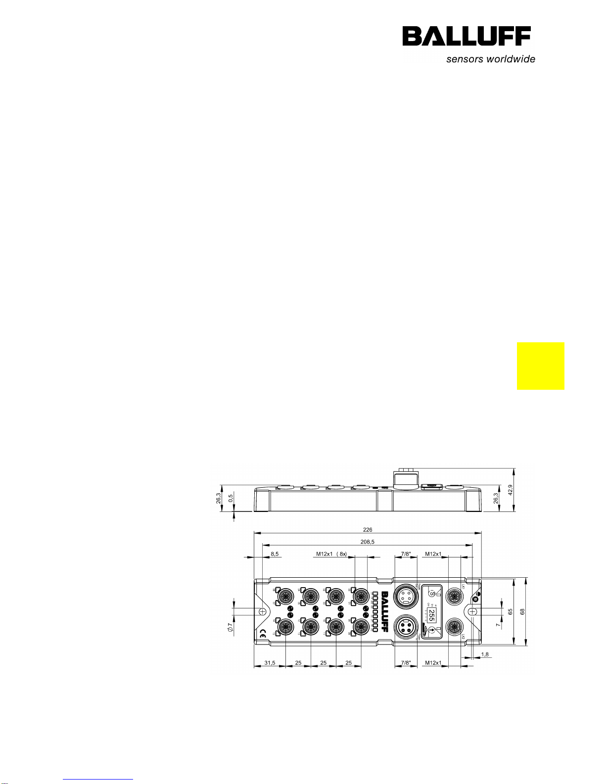
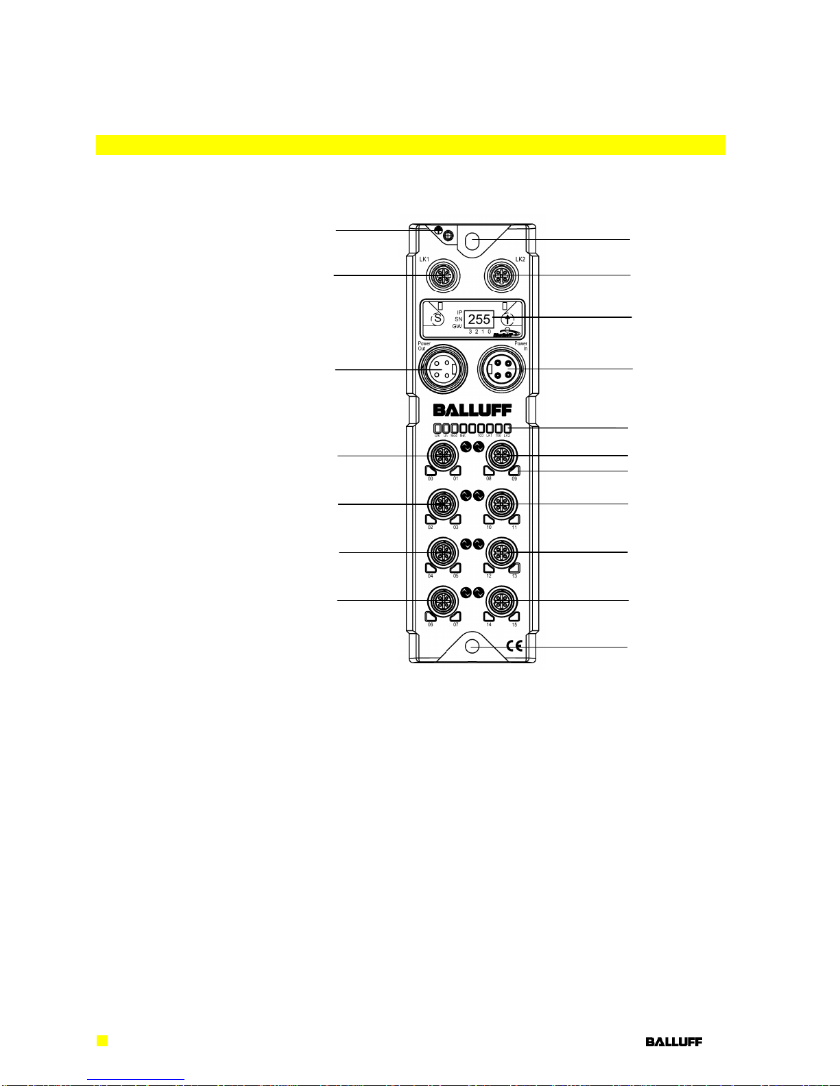
Balluff Network Interface EtherNet/IP™, BNI EIP-50x-105-R015
www.balluff.com
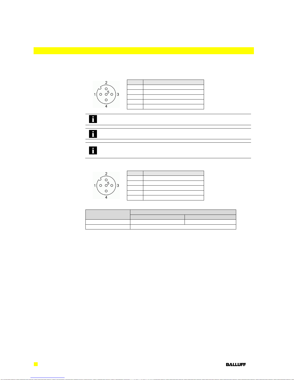
The BNI EIP-… is a decentralized IO-Link, input and output module for connecting to the
EtherNet/IP™ network.
2.2. Installation and
Startup
Note
Installation and startup are to be performed by trained technical personnel only.
Skilled specialists are people who are familiar with the work such as installation
and the operation of the product and have the necessary qualifications for these
tasks. Any damage resulting from unauthorized tampering or improper use shall
void warranty and liability claims against the manufacturer. The operator is re-
sponsible for ensuring that the valid safety and accident prevention regulations are
observed in specific individual cases.
2.3. General Safety
Notes
Commissioning and inspection
Before commissioning, carefully read the User's Guide.
The system must not be used in applications in which the safety of persons depends on the
function of the device.
Intended use
Warranty and liability claims against the manufacturer shall be rendered void by damage
from:
Unauthorized tampering
Improper use
Use, installation or handling contrary to the instructions provided in this User's
Guide.
Obligations of the owner/operator
The device is a piece of equipment in accordance with EMC Class A. This device can pro-
duce RF noise. The owner/operator must take appropriate precautionary measures against
this for its use. The device may be used only with a power supply approved for this. Only
approved cables may be connected.
Malfunctions
In the event of defects and device malfunctions that cannot be rectified, the device must be
taken out of operation and protected against unauthorized use.
Intended use is ensured only when the housing is fully installed.
2.4. Resistance to
Aggressive Sub-
stances
Note
The BNI modules always have good chemical and oil resistance. When used in
aggressive media (such as chemicals, oils, lubricants and coolants, each in a high
concentration (i.e. too little water content)), the material must first be checked for
resistance in the particular application. No defect claims may be asserted in the
event of a failure or damage to the BNI modules caused by such aggressive
media.
Note
Before working on the device, switch off its power supply.
Note
In the interest of continuous improvement of the product,
Balluff GmbH reserves the right to change the technical data of the product and
the content of these instructions at any time without notice.