Balluff Network Interface IO-Link
Montageanleitung / Installation Guide
www.balluff.com 1
Diese Montageanleitung ersetzt nicht die Bedienungsanleitung. Für eine
ordnungsgemäße Installation und Betrieb lesen Sie bitte die
Bedienungsanleitung und die dazugehörigen Sicherheitshinweise
sorgfältig durch.
Diese finden Sie zum Download unter http://www.balluff.de.
Bitte wenden Sie sich bei weiteren Fragen an unseren Kundenservice.
This Installation Guide does not replace the User´s Guide. For proper
installation and operation, please read the User´s Guide and the associ-
ated safety instructions carefully.
This is ready for you to download at http://www.balluff.com.
For any further question please contact our Customer Service.
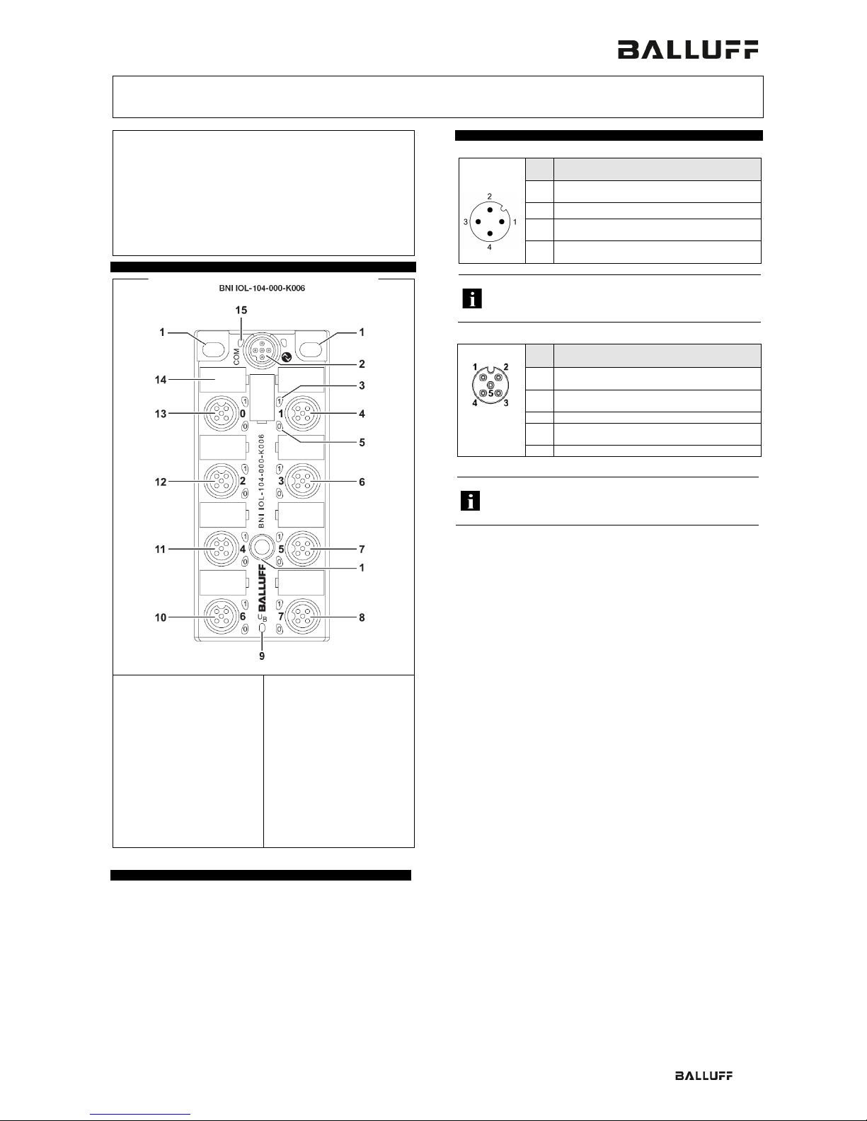
Modulübersicht / Module overview
Mounting hole
2 IO-Link Schnittstelle /
IO-Link interface
3* Status-LED: Eingang (Pin 2) /
Status-LED: Input (Pin 2) only
4 Standard Eingangs-Port 3 /
Digital Input port 3
5 Status-LED: Eingang (Pin 4) /
Status-LED: Input (Pin 4)
6 Standard Eingangs Port 3 /
Digital Input Port 3
7 Standard Eingangs Port 5 /
Digital Input Port 5
8 Standard Eingangs Port 7 /
9 Status LED: Versorgung Sen-
soren/
Status LED “Power Supply”
10 Standard Eingangs Port 6 /
Digital Input Port 6
11 Standard Eingangs Port 4 /
Digital Input Port 4
12 Standard Eingangs Port 2 /
Digital Input Port 2
13 Standard Eingangs Port 0 /
Digital Input Port 0
14 Beschriftungsschild /
Label
15 Status-LED IO-Link
Status-LED IO-Link
*Nur bei / Only for BNI IOL-104-000-K006
Mechanische Anbindung / Mechanical connections
Das Modul wird mit 3 Schrauben maximal M4 und 3 Unterlegscheiben
befestigt.
The module is attached using 3 M4 screws and 3 washers.
Elektrische Verbindungen / Electrical connection
IO-Link Interface
M12 A-coded Pin Funktion / Function
Modul- / Sensorversorgung +24V, 1.6 A/
Module / sensor power supply+24V, 1.6 A
GND, Bezugspotential /
GND, reference potential
C/Q, IO-Link-Datenübertragungskanal /
C/Q, IO-Link data transmission channel
Nicht verwendete Buchsen müssen mit Blindkappen versehen
werden, damit die Schutzart IP 67 gewährleistet ist
Unused ports socket must be fitted with cover caps to ensure
Port
M12
A-coded
female
Pin Funktion / Function
1
* Nur bei / Only for BNI IOL-104-000-K006
Die digitalen Eingänge entsprechen der Eingangskennlinie nach
EN 61131-2, Typ 2.
For the digital sensor inputs follow the input guideline per


