Inhalt
1Notes for the user 2
1.1. About this guide 2
1.2. Structure of the guide 2
1.3. Typographical Conventions 2
Enumerations 2
Actions 2
Syntax 2
Cross references 2
1.4. Symbols 2
1.5. Abbreviations 2
2Safety 3
2.1. Intended use 3
2.2. Installation and startup 3
2.3. General safety instructions 3
Hazardous voltage 3
3Getting Started 4
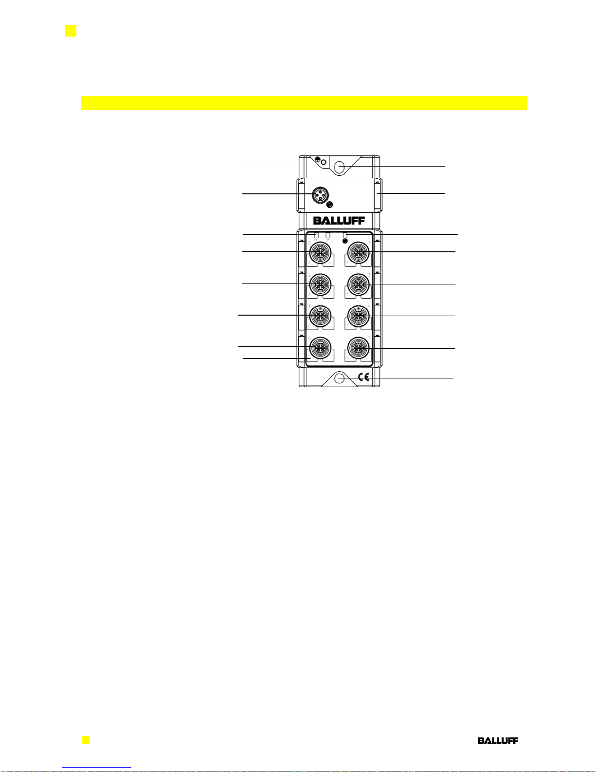
3.1. Connection overview 4
3.2. Mechanical connection 5
3.3. Electrical connection 5
IO-Link Interface 5
Connecting the sensor hub 5
Function ground 5
Module versions 5
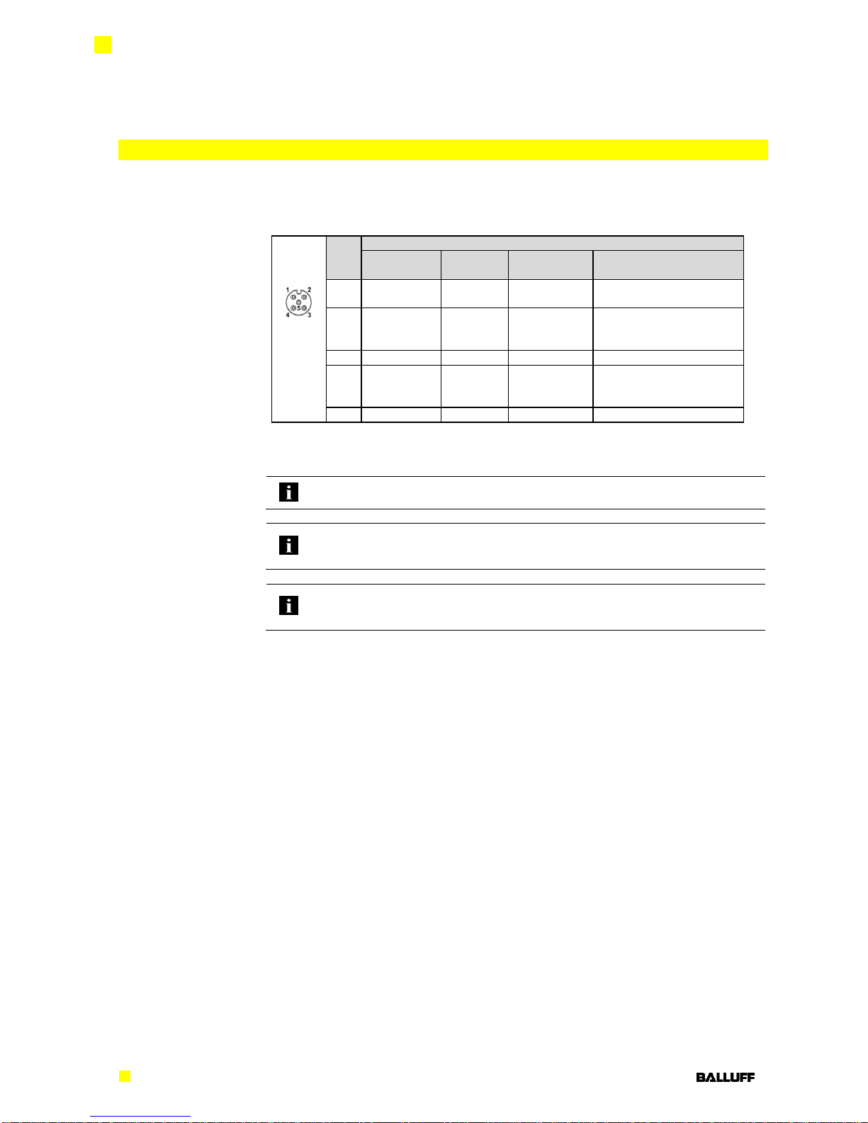
3.4. Sensor Interface 6
4IO-Link Interface 7
4.1. IO-Link Data 7
4.2. Prozess data/ Input data 9
4.3. Prozess data / Output data 13
Parameter data / Request data 14
Inversion of the inputs 40hex 16
Port Direction 41hex 16
Fault State of the outputs Pin 4, 42hex 17
Fault State of the outputs Pin 2, 43hex 17
Voltage Monitoring 44hex 18
Actuator short 45hex 18
Actuator warning 46hex 18
Identification 60hex 19
4.4. Errors 19
4.5. Events 19
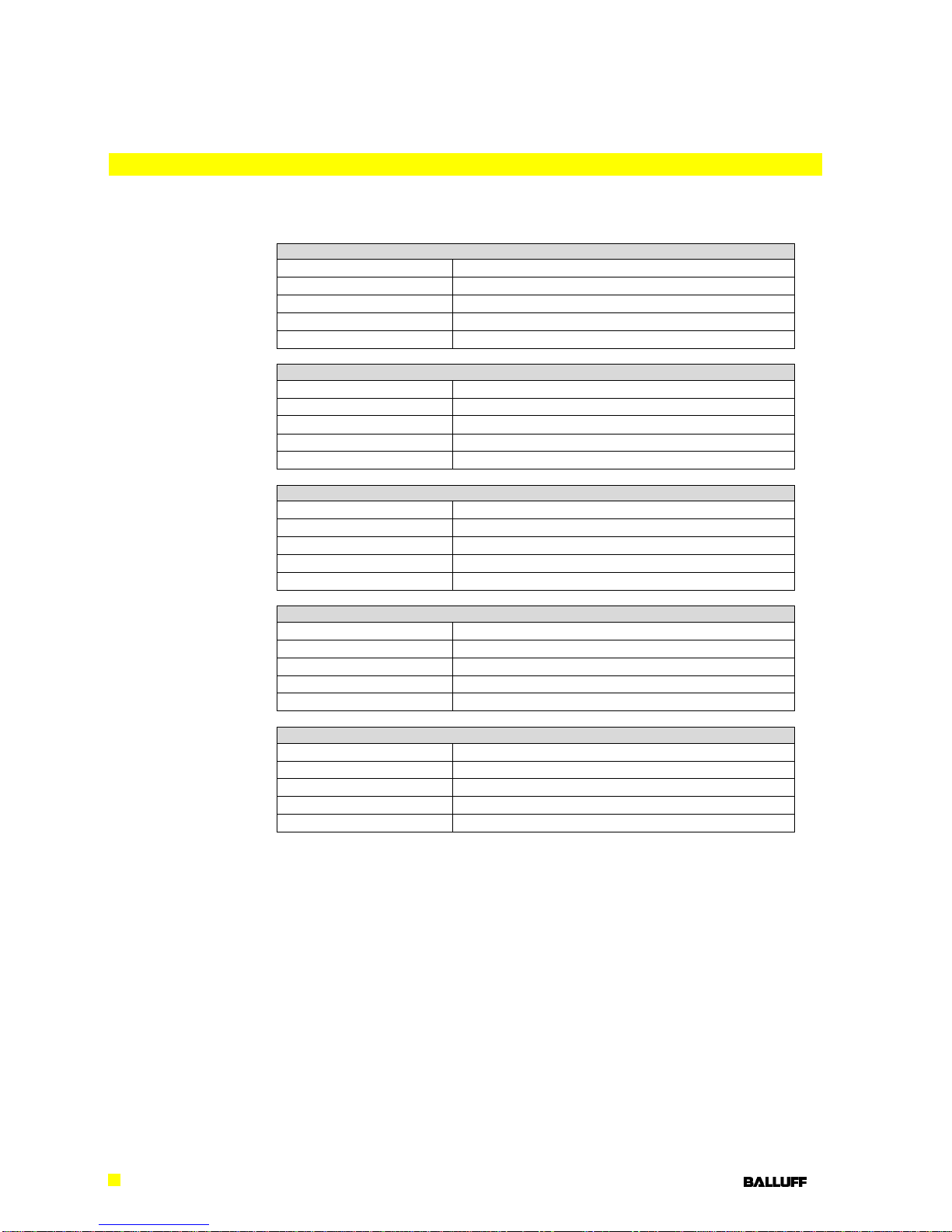
5Technical Data 20
5.1. Dimensions 20
5.2. Mechanical Data 20
5.3. Electrical Data 20
5.4. Operating conditions 20
5.5. LED indicators 21
Status LEDs 21
LED I/O-Ports 21
6Appendix 22
6.1. Product ordering code 22
6.2. Order information 22
Included material 22