1français
BNI PNT-508-055-P067 / BNI PNT-538-055-P067
Interface réseau
À propos de cette notice
La présente notice fournit des informations importantes
pour l’installation et le raccordement des modules Profinet-
IO-Link Master suivants:
– BNI PNT-508-055-P067
Symbolisation commerciale: BNI00EK
– BNI PNT-538-055-P067
Symbolisation commerciale: BNI00F8
Autres documents de référence
Vous trouverez une notice d’utilisation détaillée et des
informations supplémentaires sur ce produit sous
www.balluff.com, sur la page produit.
Utilisation conforme aux prescriptions
Le module Profinet-IO-Link Master sert de module E/S et
IO-Link déporté pour le raccordement à un bus de terrain
PROFINET, et est prévu pour un usage dans le domaine
industriel.
Le bon fonctionnement du système, conformément aux
indications figurant dans les caractéristiques techniques,
n’est garanti qu’avec les accessoires d’origine Balluff
appropriés; l’utilisation d’autres composants entraîne la
nullité de la garantie.
Toute utilisation inappropriée est interdite et entraîne
l’annulation de la garantie, et est de la responsabilité du
fabricant.
Mauvais usage raisonnablement prévisible
Le produit n’est pas conçu pour les applications et
domaines suivants et ne doit pas y être mis en œuvre:
– dans des applications orientées sécurité dont la
sécurité des personnes dépend de la fonction de
l’appareil
– dans des zones explosibles
Consignes de sécurité
TLes travaux tels que le montage, le raccordement et la
mise en service ne doivent être exécutés que par un
personnel qualifié.
Est considéré comme qualifié le personnel qui, par sa
formation technique, ses connaissances et son
expérience, ainsi que par ses connaissances des
dispositions spécifiques régissant son travail, peut
reconnaître les dangers potentiels et prendre les mesures
de sécurité adéquates.
Il est de la responsabilité de l’exploitant de veiller à ce
que les dispositions locales concernant la sécurité soient
respectées.
L’exploitant doit en particulier prendre les mesures
nécessaires pour éviter tout danger pour les personnes et
le matériel en cas de dysfonctionnement du produit.
Le produit ne doit pas être ouvert, transformé ou modifié.
En cas de dysfonctionnement et de pannes du produit,
celui-ci doit être mis hors service et protégé contre toute
utilisation non autorisée.
De façon générale, les modules BNI présentent une bonne
résistance aux produits chimiques et aux huiles. En cas
d’utilisation dans des produits agressifs (par exemple
produits chimiques, huiles, lubrifiants et liquides de
refroidissement) à des concentrations élevées (par
exemple en raison d’une faible teneur en eau), la résistance
des matériaux doit être vérifiée au préalable en fonction de
l’application. En cas de défaillance ou d’endommagement
des modules BNI causé par de tels produits agressifs,
toute réclamation pour vices de fabrication est exclue.
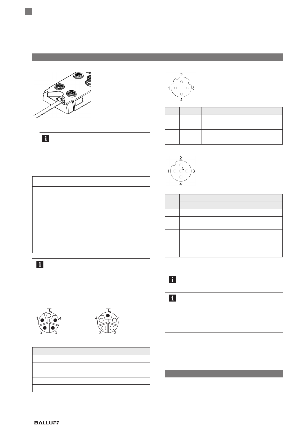
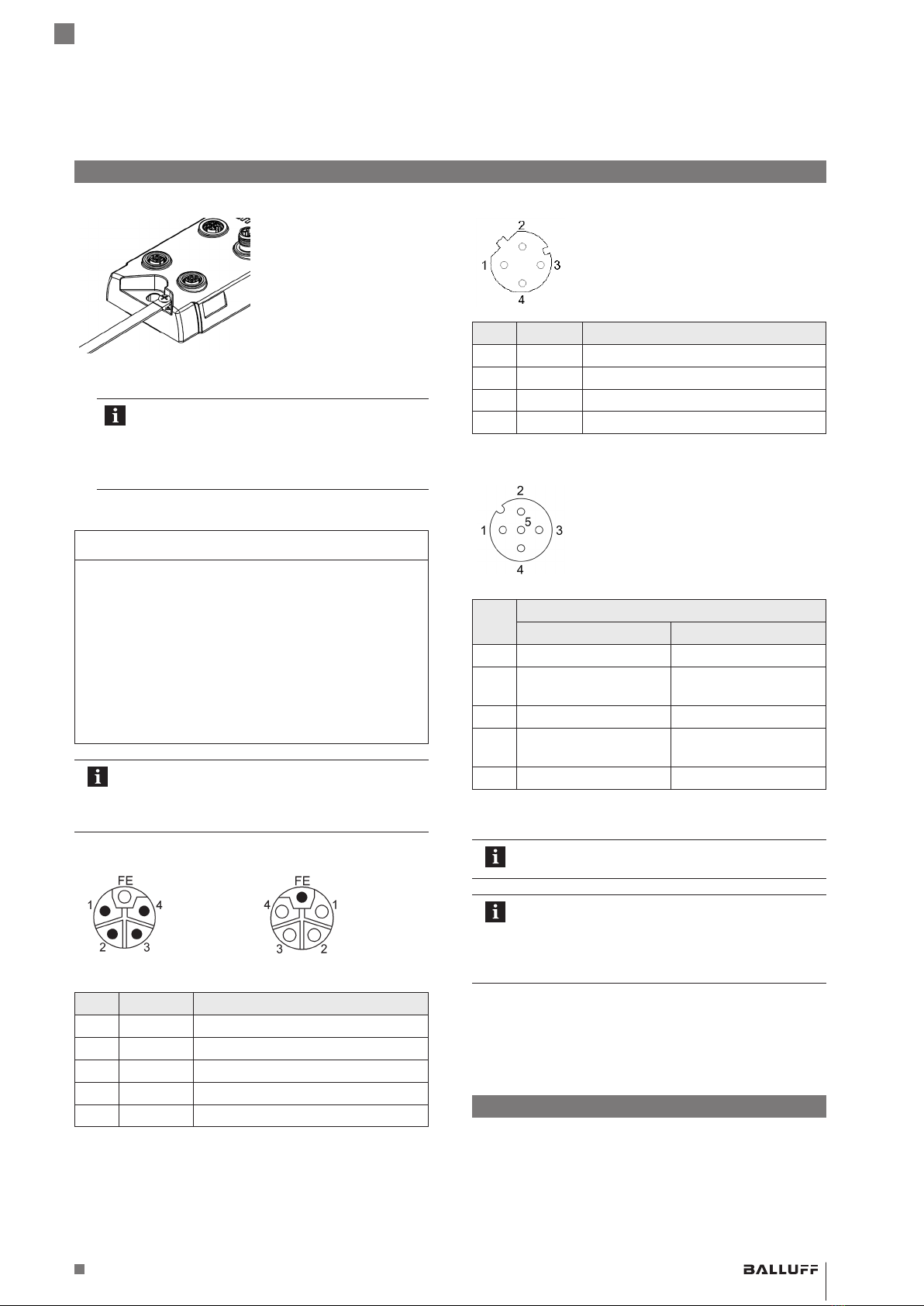
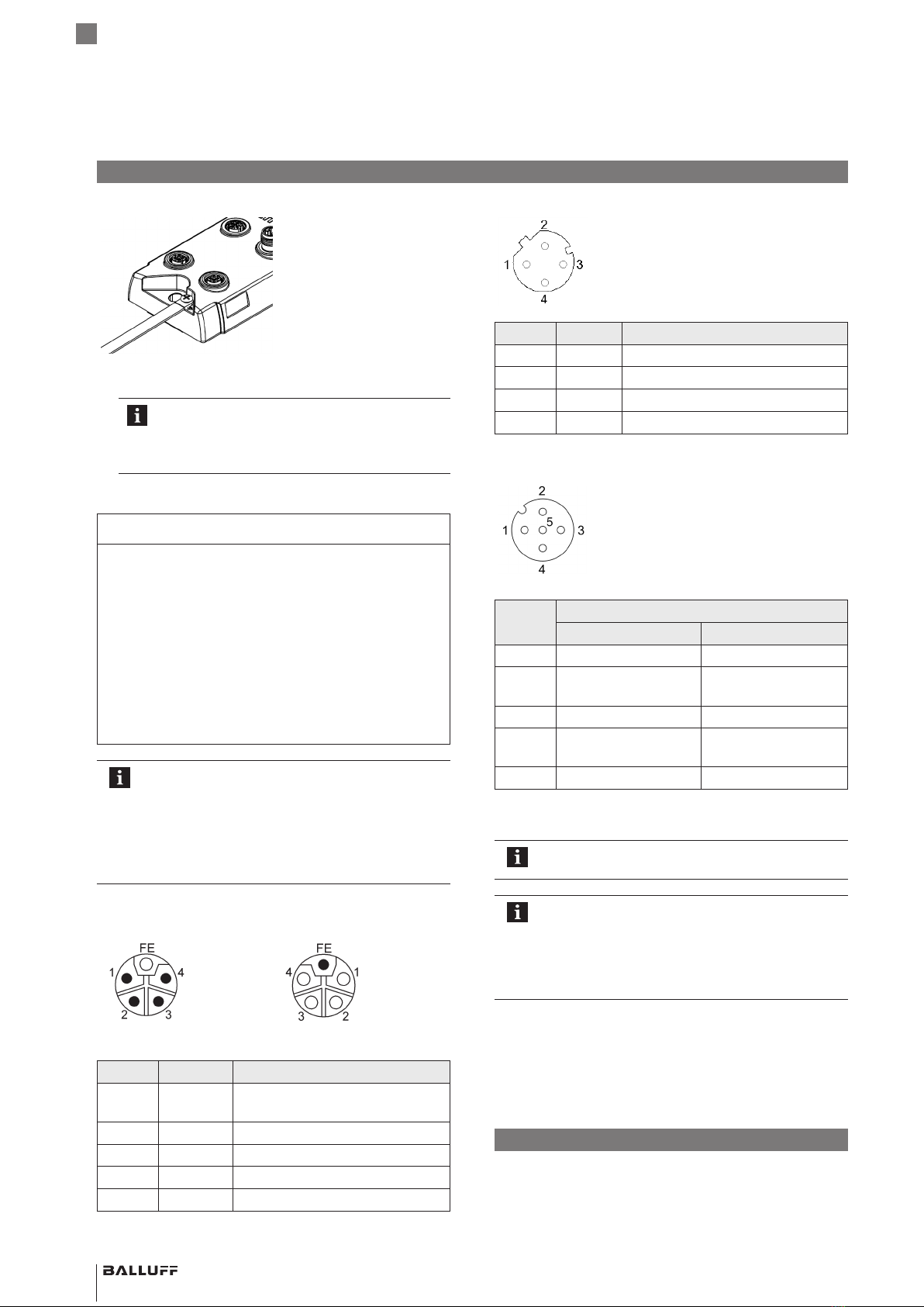
Montage
Fixer le module avec 2vis M6 en utilisant les trous de
fixation.
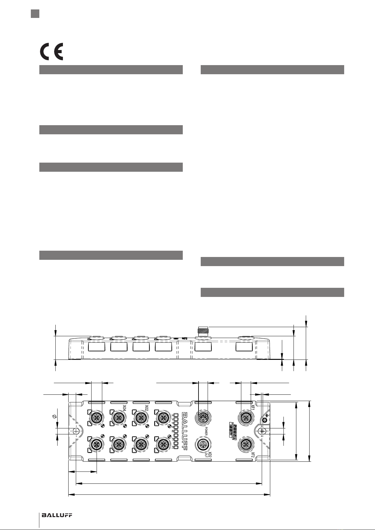
Dimensions
00
00
00 00
IN
100 100
00
01
00 01
01 01
00
01 00 01
01 01
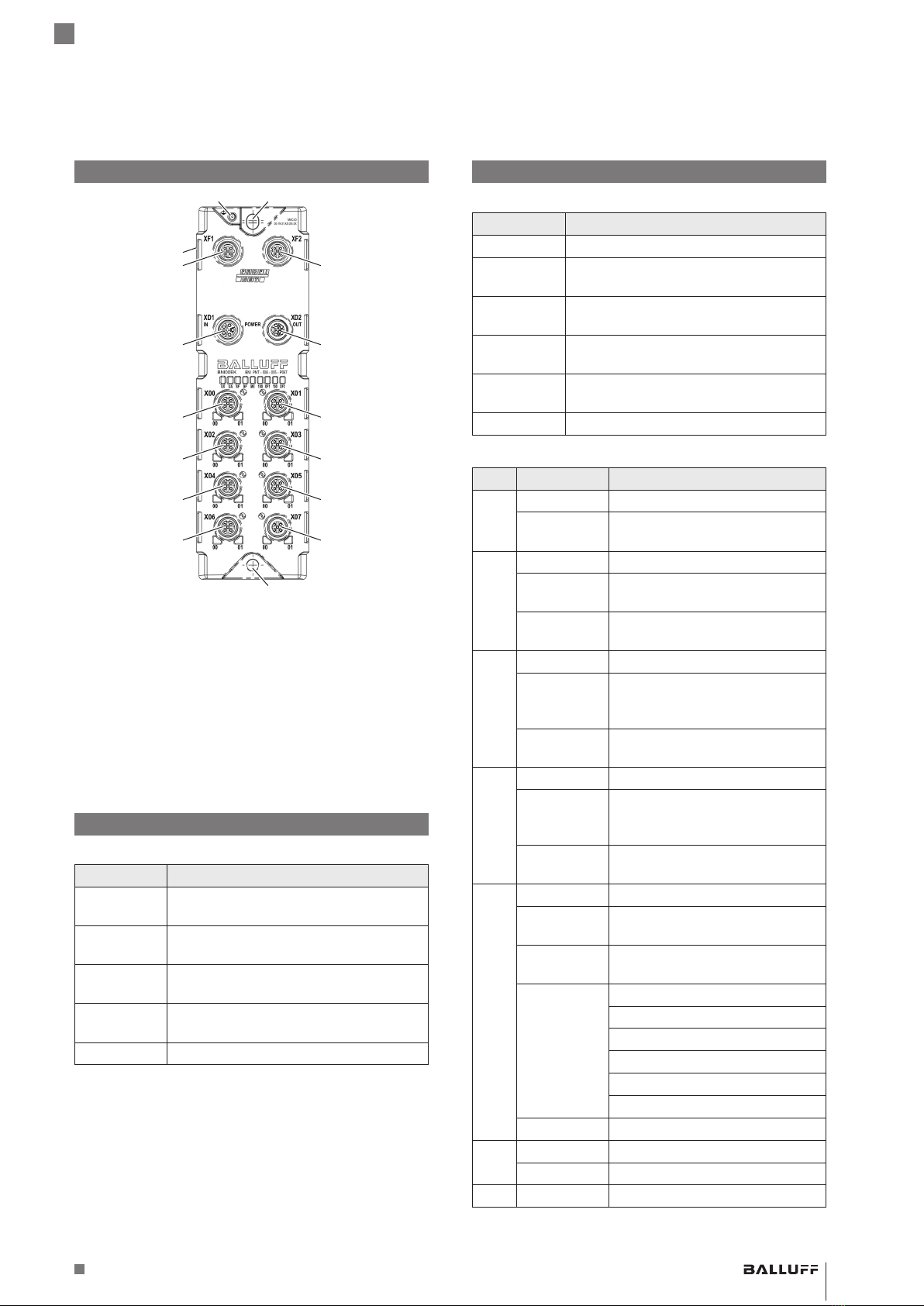
X00
XD1
BNI00EK
BNI PNT - 508 - 055 - P067
X01
X03
X05
X06 X07
MAC-ID
00-19-31-XX-XX-XX
M12x1 (8x) M12x1 (3x)
M12x1 (male)
226
208,50
7
8,50
7
65
68
1,80
31,50
0,50
26,30
36,80
26,30
00
00
00 00
IN
100 100
00
01
00 01
01 01
00
01 00 01
01 01
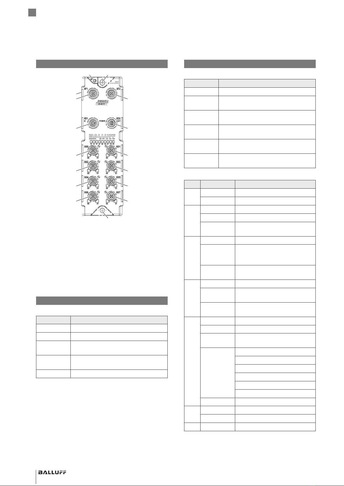
X00
XD1
BNI00EK
BNI PNT - 508 - 055 - P067
X01
X03
X05
X06 X07
MAC-ID
00-19-31-XX-XX-XX
M12x1 (8x) M12x1 (3x)
M12x1 (male)
226
208,50
7
8,50
7
65
68
1,80
31,50
Avec le symbole CE, nous certifions que nos
produits répondent aux exigences de la
directive UE actuelle.