Bame Delma POLARIS 4 User manual

POLARIS 4
MANUAL
ELECTRONIC
CONTROL BOARD
FOR SLIDING GATES

!!! ATTENTION - NOTICE FOR THE INSTALLER !!!
The bridges present on the contacts STOP, SENSITIVE EDGE, PHOTOCELLS, will
not be installed anymore by BAME s.r.l. for safety and normative reasons.
If one more of these contacts will not be utilised for any reason, the installer must
insert a bridge on the contacts to assure a correct operation of the control board.
Always follow the european standard specifications for garage doors and gates,
EN12453 and EN12445.

POLARIS 4
POLARIS 4 MANUAL SUMMARY
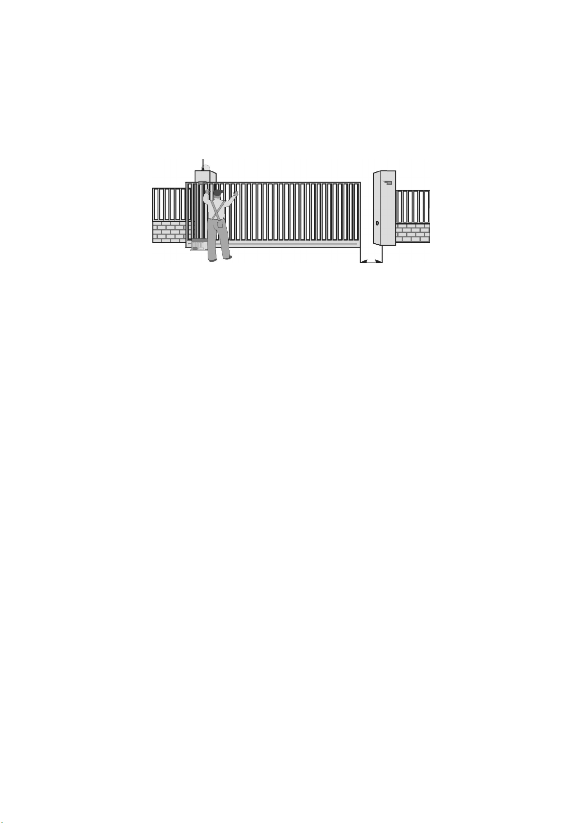
- Assembl diagram .................................................................................................................. 4
- List of electric contacts ............................................................................................................. 5
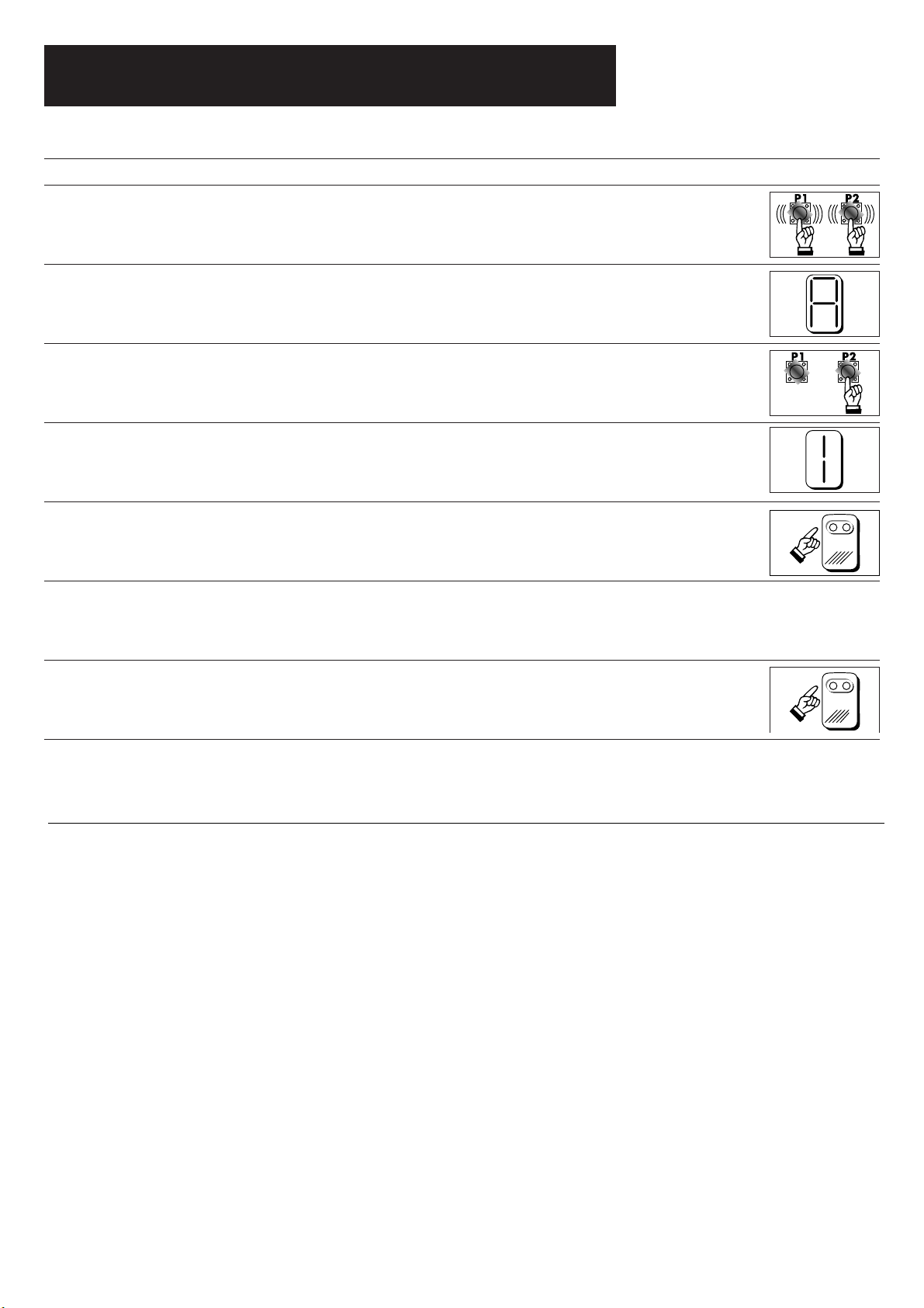
- Programming the work time ..................................................................................................... 8
- Programming of motor torque and timing:
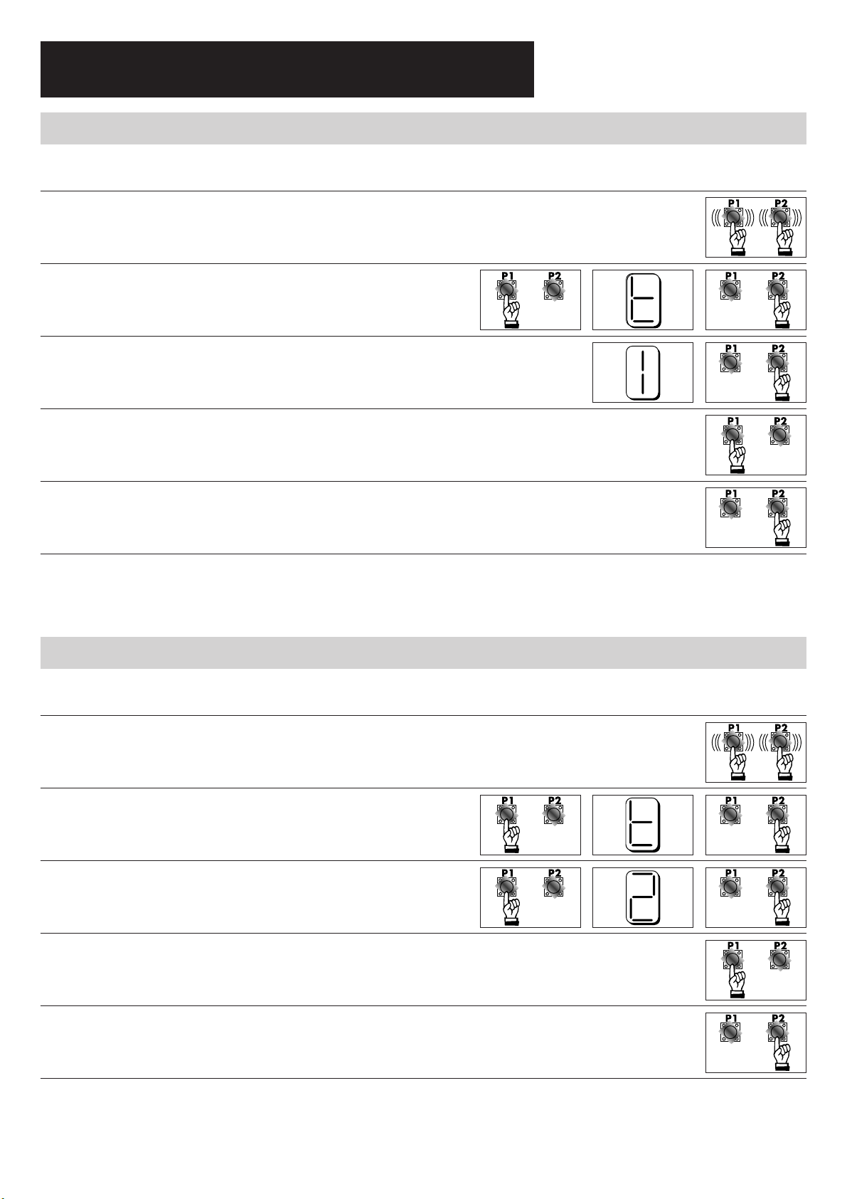
• Parameter T1 : motor torque for normal work phase ...................................................... 9
• Parameter T2 : motor torque for lagging phase .............................................................. 9
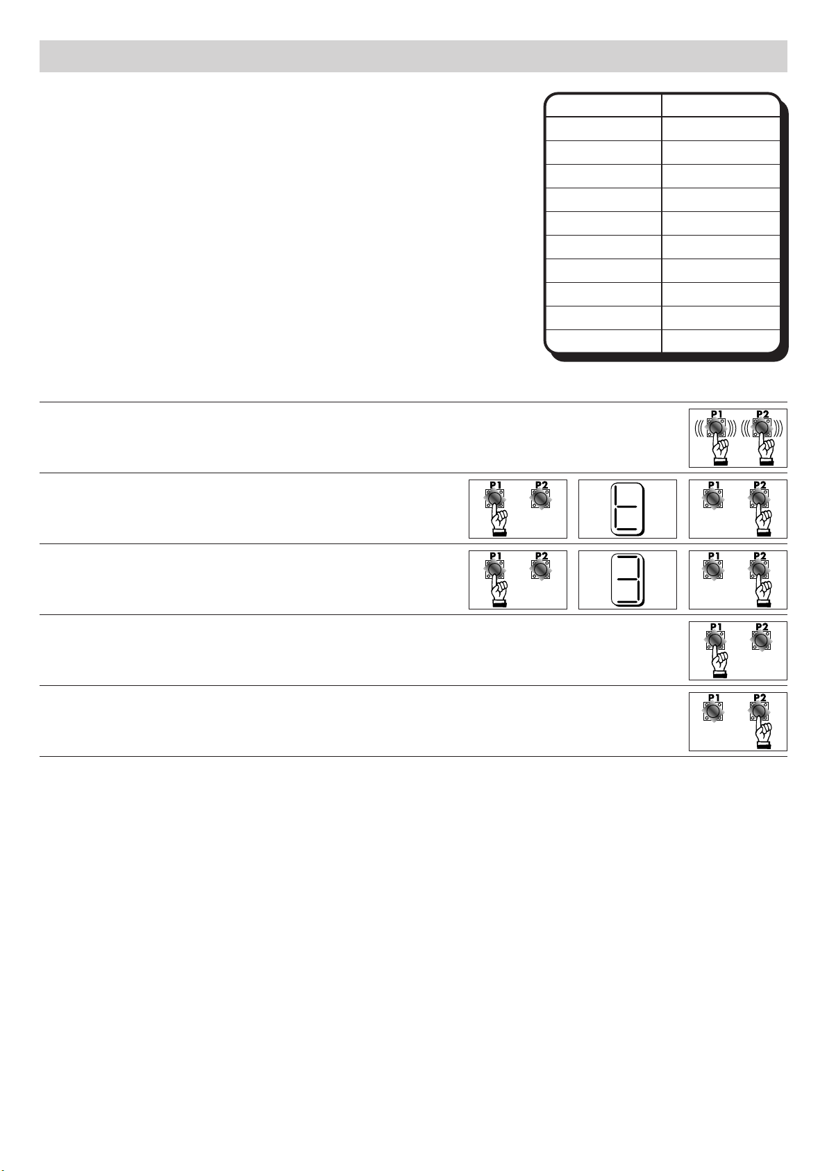
• Parameter T3 : extra time ...................................................................................... 10
- Programming of secondar parameters:
• Parameter T4 : timing of photocell operated closure ....................................................... 11
• Parameter T5 : timing of automatic closure .................................................................... 12
• Parameter T6 : timing of courtes light .......................................................................... 13
• Parameter T7 : timing for pedestrian opening ................................................................ 14
• Parameter T8 : motor brake .......................................................................................... 15
- Programming of remote control codes:
• Parameter C1 : step-b -step logic code ......................................................................... 16
• Parameter C2 : non step-b -step logic code ................................................................... 16
• Parameter C3 : pedestrian gate code ........................................................................... 17
• Parameter C4 : on/off courtes light code ..................................................................... 17
• Parameter C5 : erasing all codes .................................................................................. 18
- Programming of additional features:
• Parameter F1 : displa clutch status ............................................................................... 19
• Parameter F2 : pre-blinking .......................................................................................... 20
• Parameter F3 : enable photocells during opening operations ..........................................20
• Parameter F4 : transform pressure safet device contact in photocell 2 contact .................21
• Parameter F5 : transform “open” contact in “pedestrian open” contact ............................21
• Parameter F6 : board reset function to factor settings .................................................... 22
Note:
When installing the device, insert a switch with a contact opening of at least 3mm which ensures the equip-
ment omni-polar disconnection from the power suppl .
!!!Please read carefull this manual before proceeding with the installation of the device!!!
230V 9
Magnetothermal
switch
230V 10
T
POLARIS 4
- 3 -

Jp1
Jp2
- 4 -
ASSEMBLY DIAGRAM

CONTACTS
25 CLUTCH POWER SUPPLY (POSITIVE POLE)
26 CLUTCH POWER SUPPLY (NEGATIVE POLE)
27 CLUTCH HALL SENSOR
14 – 15 START/STOP CONTACT
14 – 16 OPEN CONTACT
17 – 18 PHOTOCELL CONTACT (Normall Closed )
17 – 19 PRESSURE SAFETY DEVICE CONTACT (Normall closed)
20 – 21 OPENING LIMITSWITCH (Insert a bridge if not used)
20 – 22 CLOSING LIMITSWITCH (Insert a bridge if not used)
23 – 24 STOP (Normall Close)
1 – 2 COURTESY LIGHT CONTACT, without electric tension ( Max. 10 A / 230 V )
3 – 4 ANTENNA ( Metallic mesh on contact 4 )
5 – 6 PHOTOCELLS POWER SUPPLY 24 VAC ( Max 150 mA )
7 – 8 BLINKER CONTACT ( T pe Quick MAX. 10 A 230 Vac )
9 – 10 MAIN POWER SUPPLY 230 VAC / 50 Hz ( Phase on 10 )
T GROUND
11 – 12 MOTOR OUTLET ( Max 500 W 230 Vac )
13 COMMON OF THE MOTOR
BOARD DEFAULT PARAMETERS
T3 EXTRA TIME = 4,5 SECONDS
T4 TIMING OF PHOTOCELLS OPERATED CLOSURE = 3 SECONDS
T5 TIMING OF AUTOMATIC CLOSURE = 30 SECONDS
T6 COURTESY LIGHT TIMING = GATE OPEN PILOT LIGHT
T7 PEDESTRIAN OPENING = 6 SECONDS
T8 MOTOR BRAKE = 270 ms
F2 PRE-BLINKING OPENING = ON
F3 PHOTOCELL ENABLED DURING OPENING PHASE = OFF
F4 TRANSFORM PRESSURE SAFETY DEVICE CONTACT IN PHOTOCELL 2 CONTACT = OFF
F5 TRANSFORM “OPEN” CONTACT IN “PEDESTRIAN OPEN” CONTACT = OFF
- 5 -

SENSOR
MAGNET
IMPUT
CLAMPS
OPEN
STOP
PRESSURE
SAFETY DEVICE
OPENING
LIMIT SWITCH
CLOSING
LIMIT SWITCH
CLUTCH
PHOTOCELLS
START/STOP
- 6 -
CHECKS TO BE DONE BEFORE
PROGRAMMING THE BOARD
• The segments on the display corresponding to STOP, PRESSURE SAFETY DEVICE and PHOTOCELLS
must be lit. These input contacts must be normally closed. (FIG.1)
• If the board for the electronic clutch is present, turn with the hand the motor shaft and verify that the
small dot on the display goes on every time the magnet pass in the sensor range. (FIG.2)

• Unlock the motor with the emergenc release s stem and move the gate until complete opening and
complete closing to verif if the limit switches are installed correctl . At each limit switch correspond
one segment on the displa (FIG.1).
• Before to start programming bring the gate in closing and lock again the motor (FIG.4)
- 7 -

1. Power the control board.
2. Memorize the remote as parameter C1 page 16
3. Press P1 and P2 simultaneousl for three seconds to begin programming the board.
4. Letter A appear on the displa .
5. Press P2 to confirm.
6. The number 1 appear on the displa .
7. Push the button of the remote memorized to start opening gate
9. Please wait that the gate opens completel . The reclosing is automatic.
10. The gate start for the reclosing.
Push the button of the remote memorized when ou want start the slowing down.
Programming he work ime
- 8 -
8. Push the button of the remote memorized when ou want start the slowing down
11. Please wait the complete closing of the gate.
Please wait that the board goes out automaticall from the programming.

Se ing he orque and lagging
Values goes from 0 to 9 0 = maximum torque 9 = minimum torque
1. Press P1 and P2 simultaneousl for three seconds
to begin programming the board.
2. Letter A appear on the displa . Scroll the menu with P1
until letter T appears on the displa .
Press P2 to confirm.
3. You should see 1 on the displa . Press P2 to confirm.
4. Select the torque from 0 to 9 with P1.
5. Press P2 to confirm.
ATTENTION!!!!!! Alwa s set and check the torque of the motor.
ATTENTION!!!!!! Ever time that the force is modified it is necessar to do again the programming
PARAMETER T1 - Torque se ing for normal working phase
Values goes from 0 to 9 0 = maximum torque 9 = minimum torque
1. Press P1 and P2 simultaneousl for three seconds
to begin programming the board.
2. Letter A appear on the displa . Scroll the menu with P1
until letter T appears on the displa .
Press P2 to confirm.
3. You should see 1 on the displa . Scroll the values
with P1 until 2 will appear on the displa .
Press P2 to confirm.
4. Select the torque from 0 to 9 with P1.
5. Press P2 to confirm.
ATTENTION!!!!!! Alwa s set and check the torque of the motor.
ATTENTION!!!!!! Ever time that the force is modified it is necessar to do again the programming.
PARAMETER T2 - Torque se ing for lagging phase
- 9 -

- 10 -
Values goes from 0 to 9
0 = 1 second of extra time
9 = 5,5 secons of extra time
1. Press P1 and P2 simultaneousl for three seconds
to begin programming the board.
2. Letter A appear on the displa . Scroll the menu with P1
until letter T appears on the displa .
Press P2 to confirm.
3. You should see 1 on the displa . Scroll the values
with P1 until 3 will appear on the displa .
Press P2 to confirm.
4. Select the value from 0 to 9 with P1
(SEE THE CHART).
5. Press P2 to confirm.
ATTENTION!!!!! The board has a factor setting 4,5 seconds of extra time.
PARAMETER T3 – Ex ra ime
Displa Seconds
0
1
2
3
4
5
6
7
8
9
1
1,5
2
2,5
3
3,5
4
4,5
5
5,5

- 11 -
Values goes from 0 to 9
0 = function OFF
9 = closure after 27 seconds from the impulse
1. Press P1 and P2 simultaneousl for three seconds
to begin programming the board.
2. Letter A appear on the displa . Scroll the menu with P1
until letter T appears on the displa .
Press P2 to confirm.
3. You should see 1 on the displa . Scroll the values
with P1 until 4 will appear on the displa .
Press P2 to confirm.
4. Select the value from 0 to 9 with P1
(SEE THE CHART).
5. Press P2 to confirm.
ATTENTION!!!!!! The control board has a default setting of 1 = 3 seconds.
ATTENTION!!!!!! If the automatic closure option T5 is turned off, the parameter T4 will be automaticall
disabled.
PARAMETER T4 - Au oma ic closure of he ga e from pho ocell impulse
Displa Seconds
0
1
2
3
4
5
6
7
8
9
OFF
3
6
9
12
15
18
21
24
27
Se ing of secondary parame ers
(no necessary for a s andard ins alla ion)

Values goes from 0 to 9
0 = function OFF
9 = closure after 240 seconds
1. Press P1 and P2 simultaneousl for three seconds
to begin programming the board.
2. Letter A appear on the displa . Scroll the menu with P1
until letter T appears on the displa .
Press P2 to confirm.
3. You should see 1 on the displa . Scroll the values
with P1 until 5 will appear on the displa .
Press P2 to confirm.
4. Select the value from 0 to 9 with P1
(SEE THE CHART).
5. Press P2 to confirm.
ATTENTION!!!!!! The control board has a default setting of 3 = 30 seconds.
ATTENTION!!!!!! This timing is valid also for the pedestrian opening.
PARAMETER T5 - Timing for au oma ic closure
Displa Seconds
0
1
2
3
4
5
6
7
8
9
OFF
10
20
30
45
60
90
120
180
240
- 12 -

Values goes from 0 to 9
0 = open gate pilot light
9 = switching off after 4,5 minutes
1. Press P1 and P2 simultaneously for three seconds
to begin programming the board.
2. Letter A appear on the display. Scroll the menu with P1
until letter T appears on the display.
Press P2 to confirm.
3. You should see 1 on the display. Scroll the values
with P1 until 6 will appear on the display.
Press P2 to confirm.
4. Select the value from 0 to 9 with P1
(SEE THE CHART).
5. Press P2 to confirm.
ATTENTION!!!!!! The control board has a default setting of 0 = open gate pilot light.
ATTENTION!!!!!! If the courtesy light will be operated with a remote control it will remain On until the next
impulse from the remote control or until the gate will be closed or opened again.
ATTENTION!!!!!! If the value open gate pilot light will be selected it will not be possible to operate the cour-
tesy light with the remote control.
PARAMETER T6 - Timing for courtesy light
Display Seconds
0
1
2
3
4
5
6
7
8
9
open gate pilot light
30
60
90
120
150
180
210
240
270
- 13 -

Values goes from 0 to 9
0 = function OFF
9 = opening of 18 seconds
1. Press P1 and P2 simultaneousl for three seconds
to begin programming the board.
2. Letter A appear on the displa . Scroll the menu with P1
until letter T appears on the displa .
Press P2 to confirm.
3. You should see 1 on the displa . Scroll the values
with P1 until 7 will appear on the displa .
Press P2 to confirm.
4. Select the value from 0 to 9 with P1
(SEE THE CHART).
5. Press P2 to confirm.
ATTENTION!!!!!! The control board has a default setting of 3 = 6 seconds.
PARAMETER T7 - Timing for pedes rian opening
Displa Seconds
0
1
2
3
4
5
6
7
8
9
OFF
2
4
6
8
10
12
14
16
18
- 14 -

The motor brake it is used to stop the movement of the gate after
the intervention of a Stop command or limit switch command.
Value goes from 0 to 9
0 = brake OFF
1 = braking of 30ms
9 = braking of 270ms
1. Press P1 and P2 simultaneousl for three seconds
to begin programming the board.
2. Letter A appear on the displa . Scroll the menu with P1
until letter T appears on the displa .
Press P2 to confirm.
3. You should see 1 on the displa . Scroll the values
with P1 until 8 will appear on the displa .
Press P2 to confirm.
4. Select the value from 0 to 9 with P1
(SEE THE CHART).
5. Press P2 to confirm.
ATTENTION!!!!!! The control board has a default setting of 1 = 50 milliseconds.
PARAMETER T8 -
Mo or brake
Displa Milliseconds
0
1
2
3
4
5
6
7
8
9
OFF
30
60
90
120
150
180
210
240
270
- 15 -

Setting the remote control codes
1. Press P1 and P2 simultaneously for three seconds
to begin programming the board.
2. Letter A appear on the display. Scroll the menu with P1
until letter C appears on the display.
Press P2 to confirm.
3. You should see 1 on the display.
Press P2 to confirm.
4. You should see 0 on the display.
Push the button on the remote to be learned.
ATTENTION!!!!!! When entering a code already stored, the code will be deleted from the memory of the board.
Parameter C1: step by step logic code (start/stop)
1. Press P1 and P2 simultaneously for three seconds
to begin programming the board.
2. Letter A appear on the display. Scroll the menu with P1
until letter C appears on the display.
Press P2 to confirm.
3. You should see 1 on the display. Scroll the values
with P1 until 2 will appear on the display.
Press P2 to confirm.
4. You should see 0 on the display.
Push the button on the remote to be learned.
ATTENTION!!!!!! When entering a code already stored, the code will be deleted from the memory of the board.
Parameter C2: non step by step logic code (open)
- 16 -
If using dipswitches remote controls before learning them on the control board, please set a personal
code with the dipswitches positioned inside the remote control.
During the learning of the remote controls we advice to disconnect the antenna and do not employ too
much time to send the code of the remote control, specially in urban areas where there are many radio
disturbs.
To comply with the European Specifications the gate must be opened on sight (15 meters), therefore the
remote controls are set to work within this distance to avoid dangerous situations and radio pollution (see
the point above).

- 17 -
1. Press P1 and P2 simultaneousl for three seconds
to begin programming the board.
2. Letter A appear on the displa . Scroll the menu with P1
until letter C appears on the displa .
Press P2 to confirm.
3. You should see 1 on the displa . Scroll the values
with P1 until 3 will appear on the displa .
Press P2 to confirm.
4. You should see 0 on the displa .
Push the button on the remote to be learned.
ATTENTION!!!!!! When entering a code alread stored, the code will be deleted from the memor of the board.
Parame er C3: pedes rian opening code
1. Press P1 and P2 simultaneousl for three seconds
to begin programming the board.
2. Letter A appear on the displa . Scroll the menu with P1
until letter C appears on the displa .
Press P2 to confirm.
3. You should see 1 on the displa . Scroll the values
with P1 until 4 will appear on the displa .
Press P2 to confirm.
4. You should see 0 on the displa .
Push the button on the remote to be learned.
ATTENTION!!!!!! When entering a code alread stored, the code will be deleted from the memor of the board.
ATTENTION!!!!!! If the parameter T6 has been set to Open gate pilot light, the courtes light cannot be operated
with the remote control.
Parame er C4: cour esy ligh code

- 18 -
1. Press P1 and P2 simultaneousl for three seconds
to begin programming the board.
2. Letter A appear on the displa . Scroll the menu with P1
until letter C appears on the displa .
Press P2 to confirm.
3. You should see 1 on the displa . Scroll the values
with P1 until 5 will appear on the displa .
Press P2 to confirm.
4. You should see 0 on the displa .
Push the button P1 and P2 simultaneousl until the exit
from programming mode.
5. All codes are now deleted.
ATTENTION!!!!!! This operation will delete all remote control codes stored in the control board memor .
Parame er C5: erasing of all remo e con rol codes

- 19 -
Addi ional fea ures
This parameter is used to check if the clutch has been detected or not, during the setting of the work time.
The additional features are not necessar for normal operations, but the are ver useful in case of parti-
cular installations.
1. Press P1 and P2 simultaneousl for three seconds
to begin programming the board.
2. Letter A appear on the displa . Scroll the menu with P1
until letter F appears on the displa .
Press P2 to confirm.
3. You should see 1 on the displa .
Press P2 to confirm.
4. If on displa appear the number 0,the clutch
is not enabled.
If on displa appears one 1 the encoder is activated.
5. Press P2 to get out
Parame er F1: display clu ch s a us (ON/OFF)
ATTENTION!!!!!! This parameter allows to visualize onl the encoder state, not to change it

- 20 -
It is possible to enable or disable the pre-blinking in the opening and closing phase following the instruc-
tion listed below.
Values goes from 0 to 1
0 = pre-blinking OFF
1= pre-blinking ON
1. Press P1 and P2 simultaneously for three seconds
to begin programming the board.
2. Letter A appear on the display. Scroll the menu with P1
until letter F appears on the display.
Press P2 to confirm.
3. You should see 1 on the display. Scroll the values
with P1 until 2 will appear on the display.
Press P2 to confirm.
4. Select the value from 0 to 1 with P1
and press P2 to confirm.
ATTENTION!!!!!! For security reasons the pre-blinking can be excluded only for the opening phase and not
for the closing phase. The control board has a default setting of 0 = pre-blinking OFF.
Parameter F2: pre-blinking
Values goes from 0 to 1
0 = photocells enabled during the closing phase
1= photocells enabled during the closing and the opening phase
1. Press P1 and P2 simultaneously for three seconds
to begin programming the board.
2. Letter A appear on the display. Scroll the menu with P1
until letter F appears on the display.
Press P2 to confirm.
3. You should see 1 on the display. Scroll the values
with P1 until 3 will appear on the display.
Press P2 to confirm.
4. Select the value from 0 to 1 with P1
and press P2 to confirm.
ATTENTION!!!!!! The control board has a default setting of 0 = photocells enabled during the closing phase.
Parameter F3: enable the photocells also during the opening phase
Table of contents
Other Bame Garage Door Opener manuals
Popular Garage Door Opener manuals by other brands

Nice
Nice Pop Instructions and warnings for the fitter

Tormatic
Tormatic B-600 manual

Roger Technology
Roger Technology BE20 Series Use and maintenance manual

Chamberlain
Chamberlain Whisper Drive Security+ 257858 owner's manual

Micom Autodoor
Micom Autodoor EDM-MD Series installation manual

LIBRA
LIBRA Gear motor 230V for sectional Installation and use manual

NASAB
NASAB E8 installation guide

Security +
Security + Elite 3885C owner's manual

Haas Door
Haas Door 610 Operation & maintenance manual

Craftsman
Craftsman 139.18687 owner's manual

SEA
SEA SATURN 24V 1500 Mounting and Connecting Instructions

Gliderol
Gliderol Glidermatic GRD Installation instructions and owner's manual