Important Safety Warnings
Please read these important safety warnings before attempting to install or use this product
Do not operate the gate motor unless the gates are in full view and free from objects such as
cars, children or people.
Children must be supervised near the gates at all times, especially when the gate motor is in
use.
Ensure that the obstruction sensing function of the gate motor is operational and adjusted
where necessary.
Keep hands and any loose clothing well clear of the gate(s) and gate motor at all times.
Disconnect the power from the mains before attempting to service the gate motor or removing
the cover.
Keep any gate controllers out of reach of children. Any wired or wireless controllers must be
installed away from any moving parts, and it must be at a minimum height of 1.5m from the
ground.
If the ‘Auto Close’ feature is enabled, then precautions should be taken to ensure the gate can
close without hitting any obstructions or suitable safety accessories are also installed.
This equipment is designed for use as a Sliding Gate Opening Device only. Do not attempt to
use for any other purpose as injury or property damage may occur.
Regularly check that all safety features and safety accessories are fully functioning.
Warning:
Failure to comply with these safety warnings or installation instructions may result in serious
personal injury and / or property damage.
Installation Checklist
Read all instructions and data sheets before installing the gate motor kit. Failure to follow the
instructions could void warranty.
The gate must to be in good operating condition. The gate needs to open and close freely for its
full length of travel and that it does not stick or bind on anything. The gate posts are correctly
and securely mounted
We recommend 1.5mm twin active lighting cable for power supply wiring and 1mm figure 8 wire
for wiring push buttons and other auxiliary items.
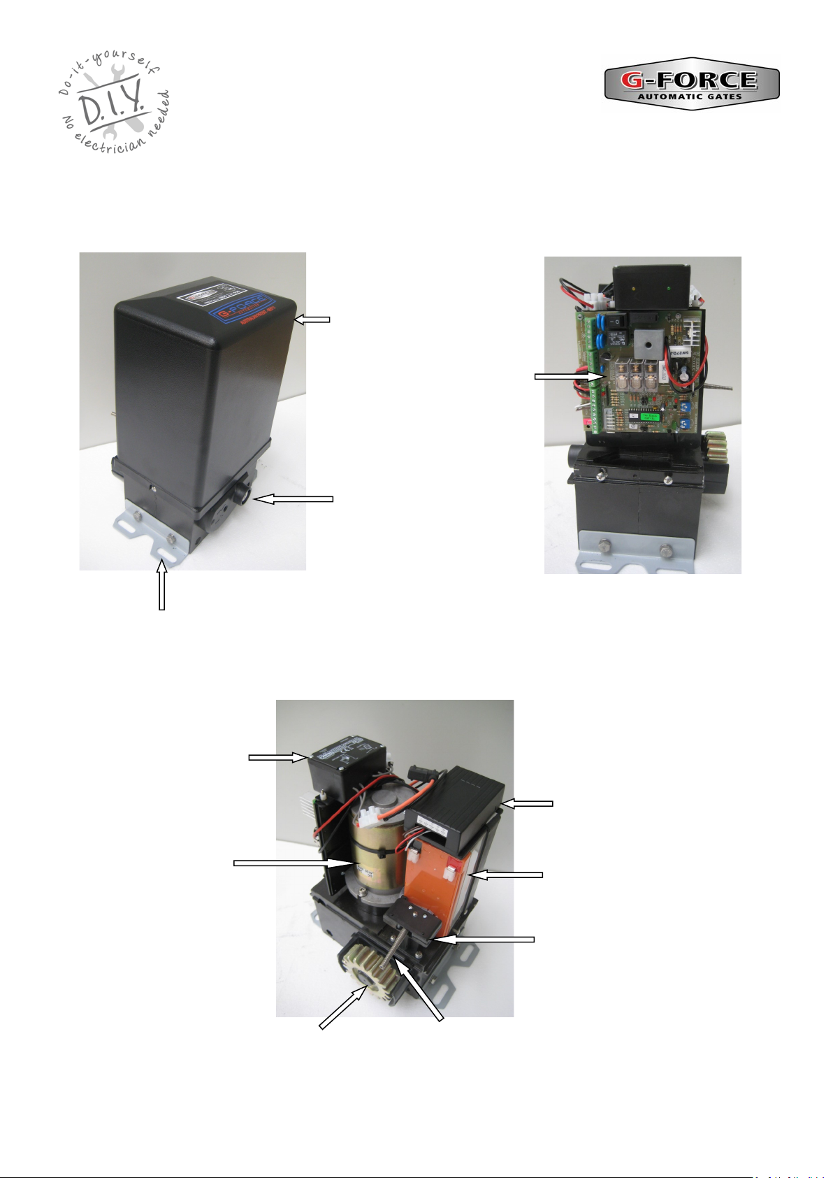
SL GATE MOTOR INSTALLATION
AND SET UP INSTRUCTIONS