SEA USER 1 User manual

USER 1 - 24V DG
24V ELECTRONIC CONTROL UNIT FOR SLIDING GATES AND BARRIERS
67411535
International registered trademark n. 2.777.971

Details
General
An appliance shall be provided with an instruction manual. The instruction manual shall give instructions for the installation,
operation, and user maintenance of the appliance.
The installation instructions shall specify the need for a grounding-type receptacle for connection to the supply and shall stress the
importance of proper grounding.
The installation instructions shall inform the installer that permanent wiring is to be employed as required by local codes, and
instructions for conversion to permanent wiring shall be supplied.
Information shall be supplied with a gate operator for:
a) The required installation and adjustment of all devices and systems to effect the primary and secondary protection against
entrapment (where included with the operator).
b) The intended connections for all devices and systems to effect the primary and secondary protection against entrapment. The
information shall be supplied in the instruction manual, wiring diagrams, separate instructions, or the equivalent.
Vehicular gate operators (or systems)
A vehicular gate operator shall be provided with the information in the instruction manual that defines the different vehicular gate
operator Class categories and give examples of each usage. The manual shall also indicate the use for which the particular unit is
intended as defined in Glossary, Section 3. The installation instructions for vehicular gate operators shall include information on
the Types of gate for which the gate operator is intended.
A gate operator shall be provided with the specific instructions describing all user adjustments required for proper operation of the
gate. Detailed instructions shall be provided regarding user adjustment of any clutch or pressure relief adjustments provided. The
instructions shall also indicate the need for periodic checking and adjustment by a qualified technician of the control mechanism
for force, speed, and sensitivity.
Instructions for the installation, adjustment, and wiring of external controls and devices serving as required protection against
entrapment shall be provided with the operator when such controls are shipped with the operator.
Instructions regarding intended installation of the gate operator shall be supplied as part of the installation instructions or as a
separate document. The following instructions or the equivalent shall be supplied where applicable:
a) Install the gate operator only when:
1) The operator is appropriate for the construction of the gate and the usage Class of the gate,
2) All openings of a horizontal slide gate are guarded or screened from the bottom of the gate to a minimum of 4 feet (1.22
m) above the ground to prevent a 2-1/4 inch (57.2 mm) diameter sphere from passing through the openings anywhere in
the gate, and in that portion of the adjacent fence that the gate covers in the open position,
3)All exposed pinch points are eliminated or guarded, and
4) Guarding is supplied for exposed rollers.
b) The operator is intended for installation only on gates used for vehicles. Pedestrians must be supplied with a separate access
opening. The pedestrian access opening shall be designed to promote pedestrian usage. Locate the gate such that persons will
not come in contact with the vehicular gate during the entire path of travel of the vehicular gate.
c) The gate must be installed in a location so that enough clearance is supplied between the gate and adjacent structures when
opening and closing to reduce the risk of entrapment. Swinging gates shall not open into public access areas.
d) The gate must be properly installed and work freely in both directions prior to the installation of the gate operator. Do not over-
tighten the operator clutch or pressure relief valve to compensate for a damaged gate.
e) (not applicable)
f) Controls intended for user activation must be located at least six feet (6’) away from any moving part of the gate and where the
user is prevented from reaching over, under, around or through the gate to operate the controls. Outdoor or easily accessible
controls shall have a security feature to prevent unauthorized use.
USER 1 - 24V DG
International registered trademark n. 2.777.971
267411535 REV 03 - 05/2013

g) The Stop and/or Reset button must be located in the line-of-sight of the gate. Activation of the reset control shall not cause the
operator to start.
h)Aminimum of two (2) WARNING SIGNS shall be installed, one on each side of the gate where easily visible.
i) For gate operators utilizing a non-contact sensor:
1) See instructions on the placement of non-contact sensors for each Type of application,
2) Care shall be exercised to reduce the risk of nuisance tripping, such as when a vehicle, trips the sensor while the gate is
still moving, and
3) One or more non-contact sensors shall be located where the risk of entrapment or obstruction exists, such as the
perimeter reachable by a moving gate or barrier.
j) For a gate operator utilizing a contact sensor:
1) One or more contact sensors shall be located where the risk of entrapment or obstruction exists, such as at the leading
edge, trailing edge, and postmounted both inside and outside of a vehicular horizontal slide gate.
2) One or more contact sensors shall be located at the bottom edge of a vehicular vertical lift gate.
3) One or more contact sensors shall be located at the pinch point of a vehicular vertical pivot gate.
4) Ahardwired contact sensor shall be located and its wiring arranged so that the communication between the sensor and
the gate operator is not subjected to mechanical damage.
5) A wireless contact sensor such as one that transmits radio frequency (RF) signals to the gate operator for entrapment
protection functions shall be located where the transmission of the signals are not obstructed or impeded by building
structures, natural landscaping or similar obstruction. A wireless contact sensor shall function under the intended end-
use conditions.
6) One or more contact sensors shall be located on the inside and outside leading edge of a swing gate.Additionally, if the
bottom edge of a swing gate is greater than 6 inches (152 mm) above the ground at any point in its arc of travel, one or
more contact sensors shall be located on the bottom edge.
7) One or more contact sensors shall be located at the bottom edge of a vertical barrier (arm).
Revised 56.8.4 effective February 21, 2008
Instruction regarding intended operation of the gate operator shall be provided as part of the user instructions or as a separate
document. The following instructions or the equivalent shall be provided:
IMPORTANT SAFETY INSTRUCTIONS
WARNING – To reduce the risk of injury or death:
1. READAND FOLLOW ALL INSTRUCTIONS.
2. Never let children operate or play with gate controls. Keep the remote control away from children.
3.Always keep people and objects away from the gate. NO ONE SHOULD CROSS THE PATH OF THE MOVING GATE.
4. Test the gate operator monthly. The gate MUST reverse on contact with a rigid object or stop when an object activates the non-
contact sensors. After adjusting the force or the limit of travel, retest the gate operator. Failure to adjust and retest the gate
operator properly can increase the risk of injury or death.
5. Use the emergency release only when the gate is not moving.
6. KEEP GATES PROPERLY MAINTAINED. Read the owner’s manual. Have a qualified service person make repairs to gate
hardware.
7. The entrance is for vehicles only. Pedestrians must use separate entrance.
8. SAVE THESE INSTRUCTIONS.
USER 1 - 24V DG
International registered trademark n. 2.777.971
3
67411535 REV 03 - 05/2013

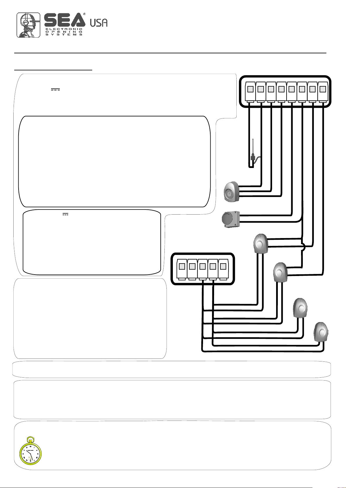
USER 1 - 24V DG
MASTER / SLAVE (CN4)
RADIO MODULE (CNA)
Receiver module connector
JOLLY (CN3)
Connector Programmer Jolly
123 4 5 6 7 8 910 11 12 13
CN1
Start
Stop
24V Aux
(500 mA max)
24V (Flash)
Common
Antenna
START Ped.
Common
Photocell 1
Photocell 2
Common
Flash (-)
Edge
LIGHT (CN5)
Max 100mA
POWER (CN8)
24V~
MOTOR (CN6)
M
Max 200W
CN7
+-
S
123
28V Battery charger
Positive battery
Negt e
btey h graiv atr care
NOTE: When using magnetic
limit switches consider the
respective inputs as N.O.
LIMIT SWITCH (CN2)
Limit switch Cl.1 (Yellow)
24V (Red)
Common (White)
Limit switch Op.1 (Green)
1
WARNING: The control unit is designed with the automatic detection of not used
N.C. inputs (photocells, Stop and Limit switch) except the SAFETY EDGE input.
CONNECTIONS
International registered trademark n. 2.777.971
467411535 REV 03 - 05/2013

DESCRIPTION OF COMPONENTS ............................................................................................6
GENERAL INFORMATION ...........................................................................................................7
QUICK START ..............................................................................................................................8
SELFLEARNING WORKING TIME ..............................................................................................9
SELECTION OF SETTINGS.......................................................................................................10
RADIO TRANSMITTER LEARNING ...........................................................................................15
TRANSMITTERS CANCELLATION ............................................................................................15
WORKING LOGICS ...................................................................................................................16
PASSWORD ENTERING MANAGEMENT .................................................................................16
JOLLY PROGRAMMER PARAMETER SETTING .....................................................................17
START, STOP, PEDESTRIAN START, ANTENNA, PHOTOCELL CONNECTIONS ..................19
LIMIT SWITCH, SENSOR BARRIERS ......................................................................................20
ALARM DESCRIPTION .............................................................................................................20
POWER SUPPLY, MOTOR CONNECTION, EDGE, BUZZER AND EXTERNAL RECEIVER ...21
MASTER-SLAVE FUNCTION .....................................................................................................22
BATTERY CONNECTION .........................................................................................................22
TROUBLE SHOOTING ..............................................................................................................23
WARNING, MAINTENANCE AND WARRANTY .........................................................................23
USER 1 - 24V DG
INDEX
International registered trademark n. 2.777.971
5
67411535 REV 03 - 05/2013

DESCRIPTION OF THE COMPONENTS
CN1 = Input/Output connector
CN2 = Limit switch connector
CN3 = Jolly connector
CN4 = Master/slave connector
CN5 = Courtesy light output plug
CN6 = Motors connector
CN7 = Batteries connector
CN8 = Power connector
CNA = Receiver connector
CNP = Programming connector
OK = Programming button
DOWN = Programming button
UP = Programming button
RD1 =Motors piloting Mosfet
RD3 = Motors piloting Mosfet
R1 = Motors command relay
R2 = Motors command relay
PR1 = Rectifier jumper
F1 = Fuse 6.3 AT
USER 1 - 24V DG
CN8 F1
CN1
CNA
CN3
CN5
CNP
CN6
RL2
RL1
CN2
CN4
CN7
UP DOWN OK
RD3
RD1
PR1
DISPLAY
1 2 3 4 5 6 7 8 9 10 11 12 13
1
6
International registered trademark n. 2.777.971
67411535 REV 03 - 05/2013

GENERAL INFORMATION
TECHNICAL SPECIFICATIONS
Control unit power supply
Absorption in stand by
Max. motor charge
Max. accessories charge 24V
Max. Flash light charge
Environment temperature
Protection 24V~
Function logic
Opening/closing time
Time of pause
Thrust
Slow down
Input on connecting terminal
Output on connecting terminal
Board dimensions
Specifications of optional batteries
Specifications of external enclosure
Special accessories
The information in this section of the manual are only for technicians or for qualified or authorized
installers.
GENERAL CHARACTERISTICS
The USER 1 24V DG control unit has been designed to manage one low voltage motor with or without electronic limit
switches.
It is of very small size and the big news is the LCD display on board that let you view and set in a simple and complete
way all functions of the control unit.
USER 1 - 24V DG
24 V~
30 mA
200W
24V 250mA
24V (FL) 15W max.
-20°C +50°C
F1 (6.3 AT)
Automatic/S.by Step1/S.By Step2/Sec./Dead man/2Butt.
In selflearning in programming phase
Adjustable (from to 4 min)
Adjustable Opening and Closing
Adjustable Opening and Closing
Battery power supply / Total opening / Pedestrian
opening adjustable / Balanceable edge /
Stop / Limit switch opening and closing / Photocell 1
and Photocell 2
24V(FL) / Light (Max 100 mA) /
Motor 24V / 24Vaux
156 x 100 mm
24V Pb 1.2Ah min.
305 x 225 x 125 mm - Ip55
Battery charger card (cod.23101105),
Programmer JOLLY (cod.23105276),
Programmer OPEN (cod.23105290)
D sb
The herein reported functions are available starting from revision 24.
International registered trademark n. 2.777.971
7
67411535 REV 03 - 05/2013
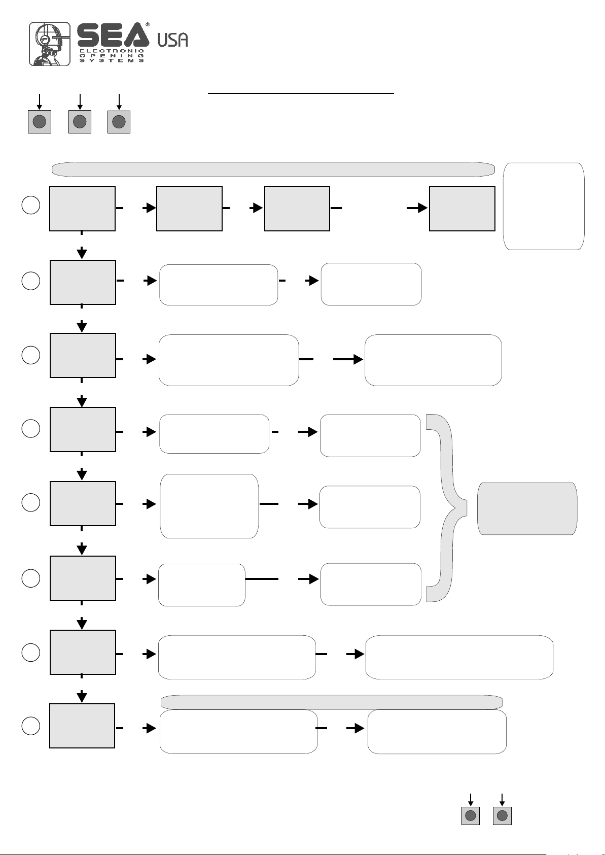
MENU
SEA
SET
Trs
U
MENU
SEA
SET
strt
MENU
SEA
SET
push
MENU
SEA
SET
e
UU
MENU
SEA
SET
ot
U
MENU
SEA
SET
MENU
SEA
SET
logc
MENU
SEA
SET
t.pau
MENU
SEA
SET
st.ps.
MENU
SEA
SET
Prg
U
MENU
SEA
SET
st.pr.
OK to exit Menu
or press the
button of the next
TX to be stored
Choose the type of
motor with
UP or DOWN
Skip this step if you do not want to program a transmitter
With UP or DOWN
choose
the desired logic
To confirm and return
to main menu
With UP or DOWN
choose a delay for
automatic closing
With UP or DOWN
Choose ON
With UP or DOWN choose ON
to start times learning
At the end of the selflearning
the control unit returns automatically
to the main menu
With
UP or DOWN Choose
ON to start test
To confirm and return to
main menu
Skip this step if a TX has already been stored
UPDOWN
ALL OTHER PARAMETERS HAVE DEFAULT SETTINGS WHICH ARE USEFUL FOR THE 90% OF THE
APPLICATIONS BUT CAN BE HOWEVER SET THROUGH THE SPECIAL MENU. FOR ENTERING INTO THE
SPECIAL MENU PRESS THE UPAND DOWN BUTTONS AT THE SAME TIME FOR 5 S.
OK
UP DOWN
PROGRAMMING BUTTONS
QUICK START
OK
Press the
button of the
TX to be
stored
1
2
3
4
5
6
7
8
To confirm and return
to main menu
To confirm and return
to main menu
OK
OK
OK
OK OK
OK OK
OK OK
OK OK
OK OK
UP
UP
UP
UP
UP
UP
UP
OK To confirm and return
to main menu
Skip this step
if you wna tto work
in half-automatic
logic
USER 1 - 24V DG
In. T
U
Choose "ON" with UP or
DOWN button only if in
programming the motor starts
in opening
Return to menu 7,
place the gate halfway
and repeat
the times programming
OK
8
International registered trademark n. 2.777.971
67411535 REV 03 - 05/2013

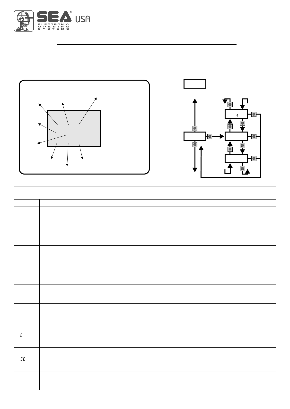
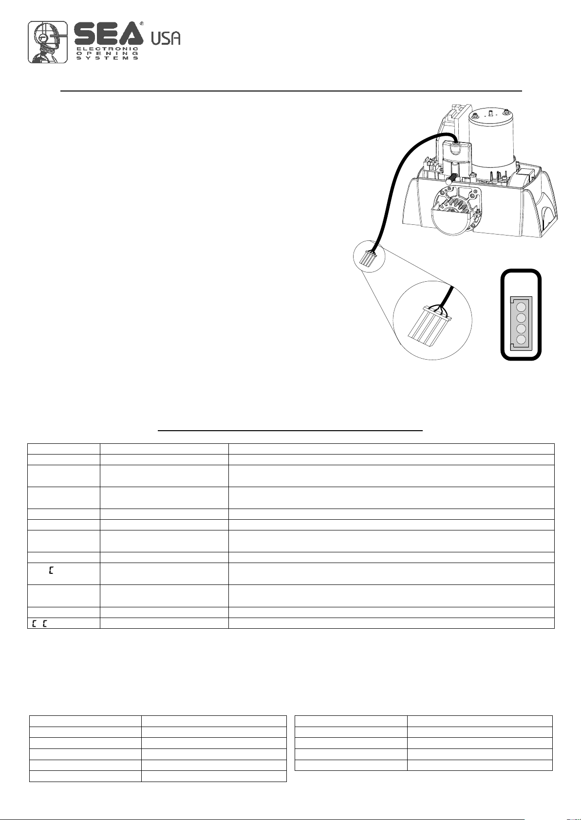
Fig.1
FF
O
The control unit is pre-set with the default settings, to start the control unit with the
DEFAULT settings just keep pressed the UP and DOWN buttons at the same time
power supplying the control unit the display shows the message init.
The DEFAULT settings are shown in the Menues table.
WORKING TIMES SELF LEARNING
USER 1 - 24V DG
Fig.6
ON
A
Fig. 2 Fig. 5
Fig. 7
Fig. 3 Fig. 8 Fig.4
U
iN. T
NOTE: When using a B200 motor or magnetic limit switches in general; make sure that the
control unit is set on magnetic limit switch before learning;
MENU SA G
Note1: Put a jumper on SAFETY EDGE contact if not used.
Note2: It is not necessary to put a jumper on the limit switches, photocells and Stop if they are
not used.
1) Disconnect the power supply (Fig. 1), release the motor (Fig. 2) and put the leaves manually
next to the stop in closing (Fig. 3-4).
Reset the mechanical lock (Fig. 5)
2) Connect the control board to the power supply (Fig.6).
3) Select on the on-board display or JOLLY programmer, the type of motor that you are using as
indicated in the dispaly administration.
4) Set the motor torque, the working speed, the deceleration and acceleration space and the
slowdown speed. If necessary also set the working logic and the other parameters.
5) Select PROG on the display, press OK and than one of the UP or DOWN buttons. Now the gate
will automatically execute a closing, opening and reclosing cylce.
Note: If the motor starts in opening, remove and re-put power supply, select on the display .
And through the UP and DOWN button put it on ON, or if you have the Jolly programmer, activate
the motor and limit switch exchange function. If the motor starts in closing and stops, remove
the power supply and reverse the motor cables, then repeat starting from point 5.
6)The self-learning is done.
ATTENTION: This procedure is potentially dangerous and should only be performed by
qualified personnel in safety conditions.
U
9
International registered trademark n. 2.777.971
67411535 REV 03 - 05/2013
SELECTION OF THE SETTINGS
Initial system
Software Version
The settings of the control unit are made through the UP, DOWN and OK buttons. The UP and DOWN buttons to scroll through
the MENUS and SUBMENUS. By pressing OK you enter from MENU into SUBMENU and confirm the choice.
Pressing the UP and DOWN buttons at the same time you access the SP MENU for special settings. Pressing the OK button for
5 seconds, you enter the TEST MENU, where you can check the operating status of all inputs.
Programming example
USER 1 - 24V DG
0.0
MENU'
strt
stop
pedo
edge
pko.1
pko.2
F a.i
F .i
u.001
barr
UP
OK
UP
UP
UP
DOWN
DOWN
DOWN
OK
OK
OK
DOWN
TRAI
ot
U
Sl d
Description
Start test
Stop test
Pedestrian start test
Safety edge test
Photocell 1 test
Photocell 2 test
Opening limit switch test
Closing limit switch test
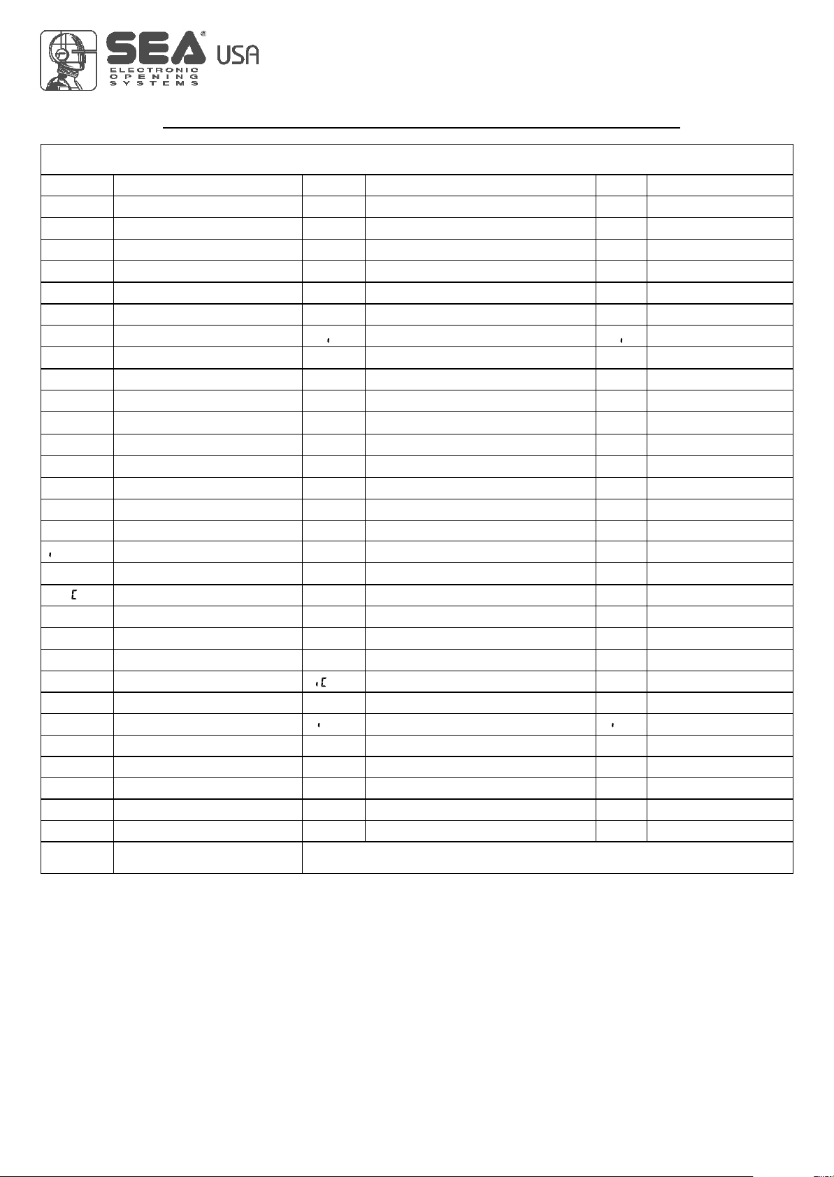
MENU FUNCTION board USER1 24V DG INPUT TESTS
(To access the Menu for input TESTS keep pressed OK for about 5 seconds)
Description
The contact must be N.O. If activating the related command on the display
the item SET lights up, the input will be working.
If SET is always on, check the wirings.
IThe contact must be N.C. If activating the related command on the display
the item SET lights up, the input will be working.
If SET is always on, make sure that the contact is a N.C. one
The contact must be N.O. If activating the related command on the display
the item SET lights up, the input will be working.
If SET is always on, check the wirings
The contact must be N.C. If activating the related command on the display
the item SET lights up, the input will be working.
If SET is always on, make sure that the contact is a N.C. one
The contact must be N.C. If activating the related command on the display
the item SET lights up, the input will be working.
If SET is always on, make sure that the contact is a N.C. One
The contact must be N.C. If activating the related command on the display
the item SET lights up, the input will be working.
If SET is always on, make sure that the contact is a N.C. one.
The contact must be N.C. If activating the related command on the display
the item SET lights up, the input will be working. If SET is always on,
make sure that the contact is a N.C. one or that the related
limit switch is not occupied.
The contact must be N.C. If activating the related command on the display
the item SET will light up, the input will be working. If SET is always on,
make sur that the contact is a N.C. one or that the related
limit swith is not occupied.
Batteries’ voltage level Batteries charge level indicator
10
International registered trademark n. 2.777.971
67411535
MENU
SEA
SET
---
--
---
DISPLAY INPUT STATUS
When the segment is
ON during self-
learning, the input
status is closed or
OFF.
Start
Start
pedestrian
Stop
Limit
Switch
opening
motor 1
Photocell 1
Photocell 2
Edge 1
Limit
Switch
closing
motor 1
REV 03 - 05/2013
SELECTION OF THE SETTINGS
USER 1 - 24V DG
11
International registered trademark n. 2.777.971
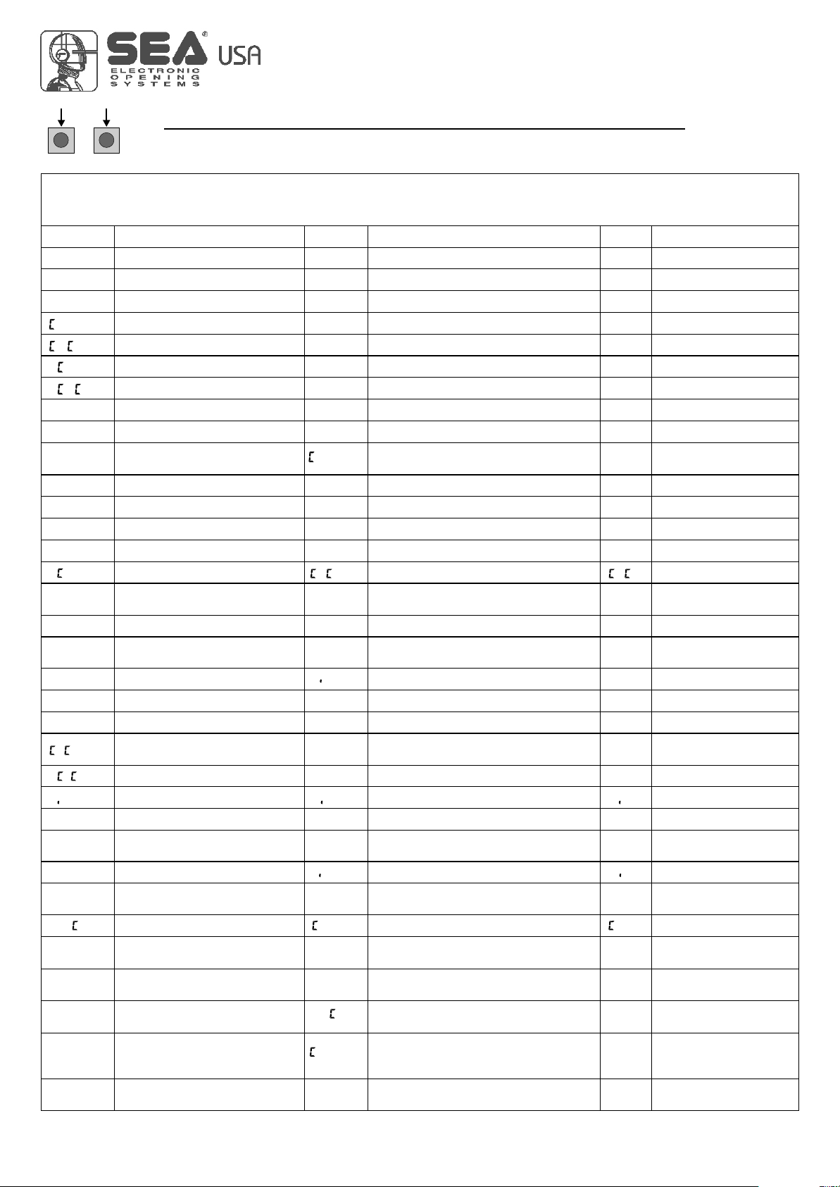
MENU functions table USER1 24V DG
Description
Description Set value
ot
U
Start
Stop
strt
stpd
Stop
del.
Trs
U
strt
stpd
Del.s
.Est
U
MENU SET Default
U
Prg
St.pr off
End
N
a to
p.p.1
p.p.2
1,2,3
Log
T.pa
N
auto
D sb
2p l
N
s u
O.pr
N
D sb
off
on
St.Ps
Verg
Erg
uerg
Erg
barr
Sl d
off
off
on
U
N. T
Motors with magnetic limit switch
S ag
U
off
Sl d
off
Off on
Start command
Off on
u.l.3
U
u.l.4
U
u.l.5
U
Verg L 3m
Verg L 4m
Verg L 5m
Exp. output
Transmitter
Pedestrian Start
Delete TX
Delete single transmitter
Motor type
Sliding
Hydraulic barrier
Motor and limit-switch inversion
Synchronized right motor
Synchronized left motor
Working logics
Automatic
Step by step type 1
Step by step type 2
Two buttons
Safety
Dead man
Time of pause
Disabled
Setting from 1s to 4min.
Start in pause
In pause start is not acceped
In pause start is accepted
Selflearning times Times learning start
Test start
Exit menu
Select END and press OK to exit the menu.The menu
deactivates automatically after 2 minutes
800
U
Mercury 800
67411535
ERG
U
Erg Maxi
REV 03 - 05/2013
SELECTION OF THE SETTINGS
UPDOWN
USER 1 - 24V DG
0 100
0 100
0 100
0 100
SPEE
sl.dn
sp.lr
pr.bl
s.str
80
40
80
70
0 100
0 100
Disb.05
70
70
P.op
P. l
Buzzer
spy
alys
beep
U
La p
N
Lgb
U
la p
D l.o
D l.
0 100
0 100
30
30
Disb Disb
l.on
MENU SP SET Default
i0e4
0
100 10e4
0 10e9
pk2
ped
8.2
s.edg
1,2,3
strt
30
20 100
strt
1,2,3
p.ped
Ped.o
rp.pa
open
stop
D sb
Y l
N. Y
D sb
D sb
U
t r
D sb
D sb
Pk.i Los Los
Par
U
L.i
N
L. O
Y l Y l
PRESS AT THE SAME TIME FOR 5 SECONDS TO ENTER OR TO EXIT THE SPECIAL MENU
SPECIAL MENU FUNCTIONS TABLE USER 1 24V DG
(To enter the Special Menu keep pressed UP and DOWN at the same time for 5 seconds.
To exit the Special Menu pressed END or keep pressed UP and DOWN at the same time for 5 seconds)
Description
Description Set value
Motors speed
Slowdown speed
Motors speed
Slowdown speed
Learning speed Learning speed
Opening torque
Closing torque
Opening torque
Closing torque
Deceleration ramp in opening
Deceleration ramp in closing
Deceleration ramp in opening
Deceleration ramp in closing
Pre-flashing Pre-flashing disabled
Pre-flashing active only
before closing
Preflashing duration
Flash output adjustment Flashing lamp
Control lamp
Always ON
Acceleration ramp
Acceleration ramp
Courtesy light Courtesy light disabled
Courtesy light setting from
1s to 4min.
Pedestrian opening
Adjusts the space of pedestrian opening
Pedestrian Pause Pause in pedestrian opening
same as in total opening
Pedestrian pause disabled
Setting from 1s to 4 min.
Number of cycles for
maintenance
Number of executed cycles
Setting from 100 to 100000
Timer management Disabled
Timer function active on photocell 2
Timer function active on
pedestrian input
Safety edge Edge is active but not protected
Edge is active and protected
by a 8k2 resistor
Photocell 1 management Photocell active in closing
Photocell active in opening
and closing
The photocell gives a command to
close during opening, pause
and closing
The photocell charging the
pausing time
Photocell active before opening
and in closing
The photocell stops in closing and
closes when released
To reset keep pressed OK for 5 s.
12
International registered trademark n. 2.777.971
67411535 REV 03 - 05/2013

SELECTION OF THE SETTINGS
UPDOWN
USER 1 - 24V DG
MENU SP SET Default
open
open
stop
rp.pa
Los
Par
U
L.i
Pk.2
alys
alys
open
pk.te
24ua
N
Pa s
Op. L
Los
pk.e
6
0 100
re.ps
0 100
D sb
U
R. Ot D sb
O.ope
all.r D sb
D sb
Op. L
O. Lo
off
on
L.ti
U
off
0 10
D ag
ph.te ph.i2
ph.i
ph.2
ph.1.2
T.opn
T.clo
0 100%
0 100%
0
0
PRESS AT THE SAME TIME FOR 5 SECONDS TO ENTER OR TO EXIT THE SPECIAL MENU
SPECIAL MENU FUNCTIONS TABLE USER 1 24V DG
(To enter the Special Menu keep pressed UP and DOWN at the same time for 5 seconds.
To exit the Special Menu pressed END or keep pressed UP and DOWN at the same time for 5 seconds)
Description
Description Set value
Photocell 2 management Photocell active in closing
Photocell active in opening
and closing
Photocell active even
before opening
Photocell stops in closing and
closes when released
The photocell gives a command to
close during opening, pause
and closing
Photocell charging the pausing time
24Vaux output management
24Vaux output always power supplied
24Vaux output power supplied only
during opening and closing
24Vaux output power supplied
only during opening
24Vaux output power supplied
only during cloisng
24Vaux output power supplied
only during pause
24Vaux output for connection of
photocell TX to autotest
Phototest economy
Output for Self-test ON only
during the operation of the motors.
Position recovery Regulates the recovery of the
motor inertia
Limit switch inversion Disabled
Adjusts the space of return after
reading of the limit switch
Anti-Intrusion alarm Disabled
Only on limit switch in closing
On limit switches in closing
and in opening
Only on limit switch in opening
Allows to keep the light switched off
when the timer is active
Allows to keep the courtesy light
switched on when the timer is active
Courtesy light with timer
management
Adjusts the amperometric tolerance
in relation to the detected stop
in closing
Adjust the amperometric tolerance
in relation to the detected stop
in opening
Amperometric tolerance
management in opening
Amperometric tolerance
management in closing
Events diagnostic Shows last event
(See alarms table)
Auto-test photocells
Auto-test active on Photo1 and Photo2
Auto-test active only on Photo1
Auto-test active only on Photo2
13
International registered trademark n. 2.777.971
67411535 REV 03 - 05/2013
MENU SP SET Default
slau
U
Ast
D sbD sb
U
A.sl
----
eND
Ps.rd ----
Ph.of 0
0 50%
SELECTION OF THE SETTINGS
UPDOWN
USER 1 - 24V DG
PRESS AT THE SAME TIME FOR 5 SECONDS TO ENTER OR TO EXIT THE SPECIAL MENU
SPECIAL MENU FUNCTIONS TABLE USER 1 24V DG
(To enter the Special Menu keep pressed UP and DOWN at the same time for 5 seconds.
To exit the Special Menu pressed END or keep pressed UP and DOWN at the same time for 5 seconds)
Description Description Set value
Photocell management
exclusion
Excludes the operation of the
photocell during closing for the
set percentage
For applications with two motors
in master-slave, you can set
the control unit as slave
For applications with two motors
in master-slave, it allows to set
the control unit as master
Master-slave management
Exit special menu
Enter password
Select END and press OK to exit the special menu.
The special menu deactivates automatically after 20 minutes.
Allows the entering of a password
which blocs the modification of the
control unit parameters (see page 16)
Disabled
14
International registered trademark n. 2.777.971
67411535 REV 03 - 05/2013

RADIO TRANSMITTER SELF LEARNING
WITH RECEIVER ON BOARD OF CONTROL UNIT
USER 1 - 24V DG
1 2 3 4
0
1
2
3
4
5
6
7
8
9
10
11
12
13
14
15
16
17
18
19
20
15
WARNING: Make the radio transmitters programming before you connect the antenna and insert the receiver into the
special CMR connector (if available) with turned off control unit. (The control unit automatically recognizes if the receiver is a RF, RF
Roll or RF Roll Plus module).
With RF Roll or RF Roll Plus module it will be possible to use only Coccinella Roll or Coccinella Roll Plus radio transmitters.
With RF UNI module it will be possible to use both Coccinella Roll Plus transmitters and radio transmitters with fixed code. The first
memorized radio transmitter will determine the type of the remaining radio transmitters.
Select through the display and press OK, now select with the UP and DOWN buttons, the command to which you want to associate the
button (it is possible to associate max. 2 commands) and press OK to confirm the choice, now press the button of the radio transmitter which
you want to associate. If the storage is successful, the display will show .
If the receiver is a Rolling Code, press twice the button of the radio transmitter that you want to program to memorize the first TX.
In the MENU it is possible to select Strt (to associate a Start command), StPd (Pedestrian Start ), (To activate the LIGHT contact),
StoP (To associate the STOP command to the TX), dEL (To delete all TX).
Notes:
- Enter radio transmitters learning only when the working cycle stops and the gate is closed.
- If the radio transmitters are Rolling Code it’s possible to memorize up to 800 codes (buttons).
- If the radio transmitters are with fixed code it will be possible to memorize up to max. 30 codes (buttons).
- You can store max. 2 of the available 4 functions. If the control unit receives a code which was already associated to another function it will be
updated with the new function.
DELETE TRANSMITTERS FROM THE RECEIVER
With modules different from RF UNI, it will be possible to delete only the entire memory of the receiver.
Proceed as follows: select from the menu DEL and hold the OK button until the display shows the message DONE.
With the RF UNI module, it will be possible to also delete the single button of the transmitter.
It can be done in two ways:
1) If you have the transmitter, or if you are using transmitters with fixed code, the cancellation can be executed by simply retransmitting the
code. Ex. Button 1 of the transmitter memorized as START; access the menu press OK, select STRT, press OK.
Send a STRT command from the transmitter and on the display will show DEL.
At this point the single button results deleted.
2) If you do not have a transmitter, or you are using a Roll Plus transmitter, you can delete the transmitter selecting the serial number of the
transmitter to be deleted.
Procede as follows: Access the menu , press OK, select DELS, press OK, choose the memory location to be deleted through the UP and
DOWN buttons, press OK, check on the display if the serial number of the transmitter to be deleted is the right one, press OK, on the display
shows SURE, if the transmitter to be deleted is the right one press OK, otherwise press the DOWN button to return to the menu .
Note: When using Roll Plus transmitters, it is recommended to record on a table similar to the below example, the serial number associateding
it to the memory location where it was stored.
!!
U
TrS
U
E
U
U
TrS
U
.Est
U
TrS
U
TrS
U
TrS
U
TrS
Transmitter
button
Memory
location Serial number Customer
TABLE
EXAMPLE
International registered trademark n. 2.777.971
67411535 REV 03 - 05/2013

USER 1 - 24V DG
FUNCTION LOGIC
AUTOMATIC LOGIC
Astart impulse opens the gate.A second impluse during the opening will not be accepted.
Astart impulse during closing reverses the movement.
SECURITY LOGIC
Astart impulse opens the gate.A second impulse during opening reverses the movement.
Astart impulse during closing reverses the movement.
STEP BY STEPTYPE 1 LOGIC
The start impulse follows the OPEN-STOP-CLOSE-STOP-OPEN logic.
STEP BY STEPTYPE 2 LOGIC
The start impulse follows the OPEN-STOP-CLOSE -OPEN logic.
DEAD MAN LOGIC
The gate opens as long as the START button of opening is pressed; releasing it the gate stops. The gate closes as long as the button connected
to the PEDESTRIAN START is pressed; releasing it the gate stops. To execute complete opening and/or closing cycles the related
pushbuttons must be constantly pressed.
2 PUSHBUTTONS LOGIC
One start opens, one pedestrian start closes. In opening the closing will not be accepted. In closing a start command reopens, a pedestrian start
command (closes) will be ignored.
NOTE 1: To have the automatic closing it is necessary to set a pause time, otherwise all the logic will be semi-automatic.
NOTE2: It is possible to choose, whether to accept or not, the start in pause, selecting in the MENU the item ST.PS and choosing ON
or OFF. By default, the parameter is OFF.
NOTE 1: To have the automatic closing it is necessary to set a pause time, otherwise all the logic will be semi-automatic.
NOTE2: It is possible to choose, whether to accept or not, the start in pause, selecting in the MENU the item ST.PS and choosing ON
or OFF. By default, the parameter is OFF.
NOTE 1: To have the automatic closing it is necessary to set a pause time, otherwise all the logic will be semi-automatic.
NOTE2: It is possible to choose, whether to accept or not, the start in pause, selecting in the MENU the item ST.PS and choosing ON
or OFF. By default, the parameter is OFF.
NOTE 1: To have the automatic closing it is necessary to set a pause time, otherwise all the logic will be semi-automatic.
NOTE2: It is possible to choose, whether to accept or not, the start in pause, selecting in the MENU the item ST.PS and choosing ON
or OFF. By default, the parameter is OFF.
With a new control unit all menus can be displayed and set and the password will be disabled.
Selecting one of the Menus and keeping UP and DOWN pressed at the same time for 5 seconds, you will access the SP Menu containing the
PS.rd. Submenu.
Pressing OK in the PS.rd. Menu, you will proceed with the entering of the numeric code of the 4-digit PASSWORD.
Use UP and DOWN to increase or decrease the number, press OK to confirm it and you will pass automatically to the entering of the next
number. Pressing OK after the last entered number the word SURE appears, confirm the activation of the PASSWORD and the message DONE
appears, pressing UP or DOWN instead you can cancel the operation and NULL will appear on the display.
Once entered the PASSWORD, it will be definitively activated, once the display switch off timeout has expired, or by turning off and on again the
control unit. Once the PASSWORD has been activated, the menus of the display can be only displayed but not set. To unlock them you must
enter the correct PASSWORD in the PS.rd menu, if the password is wrong the message ERR will appear.
At this point, if the password has been entered correctly, the menus will be unlocked and it will be possible to change the parameters of the
control unit again.
If the control unit has been unlocked through PS.rd. Menu, it is possible to enter a new and different password, using the same entering process
as for the first one; at this point, the old password will no longer be valid.
If the password has been forgotten, the only way to unlock the control unit is to contact the SEAtechnical assistance, which will assess whether
to provide the procedure to unlock the control unit or not.
Note: The password cannot be set through the Jolly terminal.
PASSWORD ENTERING MANAGEMENT
16
International registered trademark n. 2.777.971
67411535 REV 03 - 05/2013
The JOLLY programmer allows to keep under control and to change all parameters of the control unit without need to use the
buttons of the control unit. Compared to the on-board display, the programmer allows to view the programming instructions in
the user's language and in a non-encrypted way. In addition to the JOLLY programmer, the user can work comfortably standing
up without looking at the control unit.
PROGRAMMER JOLLY PARAMETERS ADJUSTMENT
Screen 2
Screen 3
Motor [Barrier / Sliding doors magnet / Erg / Verg L. 3m / Verg L. 4m / Verg L. 5m]
Screen 1
Screen 4
Screen 5
Screen 6
Language: IT Available languages: IT,EN,FR,ES [ Italian, English, Spanish, French]
Speed [30÷100 ] motor 1 speed adjustment
Sp.Decel.O1 [Off÷100 ] motor 1 slowdown space in opening adjustment
Slow Speed [30÷100 ] slowdown speed adjustment
Learn speed [30÷100 ] selflearning speed adjustment
Sp.Decel.C1 [Off÷100 ] motor 1 slowdown space in closing adjusmtent
Torque op.M1 [10÷100]% (max. motors current)
SoftStart [0÷100 ] motor 2 slowdown space in closing adjustment
Torque cl.M1 [10÷100]% (max. motors current)
Cycle [Secur./auto/deadman/step1/step2/two buttons]
Pause time [0÷240]s (pausing time in seconds, 0s halfautomatic logic)
Learning Times learning [On-Off]
Cycles [0÷... ] (Number of executed cycles )
Pedestrian [30÷100]% (Pedestrian opening rate)
Anti Intrusion [Off,Open,Close.,op.cl.] (Implies the presence of a N.C. contact on
limit switch which if released forces the motors in closing)
Preblink [Close, Off, 0÷5s] (Only before closing, OFF from 0 to 5s)
Light Time [Cycle, Off, 0÷240s] (Only during cycle, OFF from 0 to 240s)
Ph.test [1,2-1-2] (Only on Foto1, only on Foto2, on both)
Max Cycles [100÷100000] (Number of cycles for maintenance)
The arrow
indicates that the
parameter can be
changed with the +
and - buttons.
Master-Slave Master-Slave mode (OFF / Slave / Master)
USER 1 - 24V DG
17
International registered trademark n. 2.777.971
67411535 REV 03 - 05/2013
PROGRAMMER JOLLY PARAMETERS ADJUSTMENT
NOTE: For the respect of the valid European ruels on the safety of the electric gates, it is recommended to not adjust the
parameters torque on the value 100%.
USER 1 - 24V DG
Screen 11
Screen 9
Screen 8
Screen 7
Photo2 [Close./Open/stop/park/close imm./rel.pause]
Photo1 [Close/Open/stop/park/close imm./rel.pause]
Flash [Normal/Control/always/beep]
Screen 10
8k2 edge [On-Off] (On ON it allows to connect a balaced edge with 8k2
resistance)
Pos. Recovery [0÷100]% (Percentage of position recovery)
24V aux [Cycle/in open /in clos./pause/ph.test/ph.T.ECO/always]
Start pause [ON/OFF] (On ON and if the autom. clos. is on ON a start will
cause the immediate closure of the gate)
Timer [OFF-Ped-Foto2] (Allows the timer activation on the Foto2 or
pedestrian input)
Mot.inv. [ON/OFF] (Allows to changes at the same time the limit switch
and the direction of motor rotation without disconnecting the cables)
Rev. Mot. [0÷100%] (Activates an inversion at the end of closing)
P.Ped [start, Off, 0÷240 sec] (Differenciates the pedestrian pause from the
total one)
Start [ON/OFF] (Equivalent to giving a test start)
Tl.op.1 [0÷ 100%] (Tolerance between stop and obstacle)
Tl.cl.1 [0÷ 100%] (Tolerance between stop and obstacle)
Event Summarizes the last 10 events that occurred on the unit
L.Timer [Off-On] Allows to keep switched on or off the control light if a Timer
is active
Ph.off: 0% [0÷100%] (Excludes the photocell reading in closing for the
set percentage)
18
International registered trademark n. 2.777.971
67411535 REV 03 - 05/2013
START - STOP - PEDESTRIAN START - ANTENNA -
PHOTOCELL
USER 1 - 24V DG
19
International registered trademark n. 2.777.971
67411535
START (N.O.) The
An impulse given to this contact opens and closes the automation depending onthe selected logic it can be given by a key switch, a keypad,
etc. To connect the other devices refer to the related instructions leaflets. (ie. loop detectors and proximity switches).
Note1: In DEAD MAN logic it is necessary to keep pressed the Start for the opening of the automation.
Note2:
START is connected between the clamps 2 and 3 of the CN 1 terminal.
In 2 BUTTONS logic this button performs the opening.
STOP (N.C.) The STOP is connected between the clamps 2 and 5 of the CN1 terminal .
The pressure on this button immediately stops the motor in any condition/position. A start command is needed to re-start the movement.
After a stop the motor always re-starts in closing.
Photocell 1 and Photocell 2 Connections
Note: If the photocells are not connected, put a jumper between the clamps (6,7,8).
+ = 24V(FL) COM = 0V PH1 = Photocell contact 1 PH2 = Photocell contact 2
Note: For the autotest connect the TX to the 24Vaux clamp and activate theAutotest function.
The standard setting of the photocell 1 is FOTO CLOSE and the one of the photocell 2 is FOTO
OPEN. The photocell 2 can be set also as TIMER (see TIMER function).
Note3: On the Ph.Te menu you can also activate the self-test even on the single photocell.
Can be activated through on-board display or through the Jolly programmer. In both cases it’s a N.O. contact which provoques
the opening of the automation keeping it open until it is activated. When it’s released, the gate attends the set pausing time
and executes the reclosing. The TIMER command can be activated on the inputs FOTO2, START PEDESTRIAN.
Note1: When activated on the pedestrian entry, the pedestrian will be disabled also on the radio transmitter.
Note2: In case of intervention of a security device during the timer (Stop, Ammeter, Edge), to restore the movement it will be
necessary to give a start impulse.
Note3: In case of no power supply with open gate and active Timer the control unit will restore its use, otherwise if during
restore of the power supply the TIMER is not activated it will be necessary to give a start impulse for the reclosing.
TIMER
Antenna
Common
Start
Start ped.
Stop
Common
Photocell 1
CN1
1 2 3 4 5 6 7 8
Photocell 2
RX1
RX2
TX1
TX2
CN1
9 10 11 12 13
Common
24V (FL)
OPTIONS ON FOTO1 and FOTO2 adjustable on on- board display or with
JOLLY terminal.
FOTO CLOSE activation ((los): if occupied, reverses the movement in closing, during
pause it prevent the closing.
Activation repeat pause (rP.PA): If occupied, during pause it recharges the timer of pause.
In closing it reverses the movement.
FOTO OPEN activation (oPEn): If activated the photocell blocks the movement as long as
it’s busy, when released the opening continues.
FOTO PARK activation (par() : in opening it is not active; in pause are activated it
commands the closing when released, otherwise it’s not active; in closing it stops the
movement as long as it is busy, when released the closing continues.
FOTO STOP activation (STOP): When activated before the opening the photocell blocks the
automation as long as it is busy, during the opening it will be ignored. In closing the
intervention of the photocell causes the reopening.
Activation PHOTO CLOSE IMMEDIATELY: The photocell stops the gate as long as it is
occupied in both opening and closing, when released it gives a closing command (Closing
one second after release of the photocell ).
PEDESTRIAN START (N.O.) The pedestrian start can be
connected between the clamps 2 and 4 of the CN1 terminal .
This input allows a partial opening the opening space can be set
through the on-board display or through the JOLLY device.
Note1: The contact for partial opening is a N.O. Contact (Normally
open).
Note2:In 2 BUTTONS logic it is necessary to keep pressed the Start
Ped. to re-close the automation.
Note3: In dead man logic this button executes the re-closing if you
keep it pressed.
Note4: When closed during pause, the gate will reclose only after
this input has been reopened.
TIMER activation: This input can be transformed into TIMER (See
TIMER).
Options 24Vaux can be set with on-board Display or with
Jolly device.
Through the Jolly programmer it is possible to chose when having
tension on the 24Vaux output. The options are: always, only during
opening, only during cycle, only before opening or only during
pause, Ph.te and Ph.e(.
When using control units with batteries and / or solar panels, we
recommend connecting the accessories which are not used when
operator stands still (e.g. photocells) to a 24VAux output, setting
the option "Op.(L". With this setting you can save energy by
lowering power consumption in stand-by, increasing the autonomy
of the system.
REV 03 - 05/2013
LIMIT SWITCH AND SENSOR BARRIERS
Sensor barriers
This control unit comes with a detection device of motor current absorbtion which allows to
reveal possible obstacles during the opening and the closing of the gate. When this device
intervenes in opening it causes the inversion of the movement for around a second, if it
intervenes in closing it causes the total reopening.
Note1: The ammeter sensitivity is adjustable both in opening and in closing through the
on-board display or through the JOLLY terminal. With high torque the gate reverses after
5 seconds.
Attention: In case of obstacle, if the automatic reclosing is on, the gate will attempt to
close for 3 times, whereupon a start signal will be necessary to re-establish the
movment.
Limit
Switch
CN2
USER 1 - 24V DG
Limit switch
The limit switch can be connected through the special LIMIT SWITCH connector on
the control unit. The control unit can administrate mechanical, inductive and magnetic
limit switches. Only on some special applications il will not be necessary to connect
the limit switches. The control unit will automatically realize if limit switches are
present or not.
1) Through the on-board display or through the JOLLY programmer it is possible to
activate the ani-intrusion function. This function is lied to the presence of at least one
limit switch which, when free, forces the motor to re-close.
Note: if during programming phase the motor and limit switch times should not
be in phase between them, the gate will start in closing, it stops and will not
complete the selflearning of the times, at this point it will be necessary to
switch off the tension and to invert the cables of the motor. The first movement
in selflearning must always be executed in closing.
ATTENTION: When using SEA magnetic limit switches, make sure that the
motor is set on sAG.
U
20
ALARMS INDICATIONS
Flashings Number
9
2
3
6
4
Flashings Number
5
7
6
4 fast
Kind of alarm
Motors fault
Photocell in closing
Photocell in opening
Opening impact
Safety edge
Kind of alarm
Stop
Max. Reached cycles
Closing impact
Limit switch error
Battery voltage fault
F.BAT If network is not present
Motors current fault
24V Power supply fault
24Vaux output voltage
Power supply fault
FAUL
FT.24
FT.AU
FT.LI
Sure there are no short circuits on the motor or on the control unit.
Make sure there are no short circuits on the wiring or on the control unit and
no overloads.
Make sure there are no short circuits on wiring or control unit and
no overload.
Check the network or the F1 fuse.
Balanced edge input fault
Self-test photocells fault
Limit switch activation fault
Flashing lamp fault
Max. cycles
F.EDG
F.PHO
FT.f
FT.FL
Y L
Check for a 8.2 Ohms resistive value on the edge input, if not available
enter it, or disable the reading of the 8k2 in the special menu.
Check the photocells operation and / or connections on the control unit.
Check the operation of both limit switches and / or correspondence
between movement direction of the motor and engaged limit switches.
Check connections and / or conditions of the lamp.
Maintain and / or reset the number of performed cycles.
Signals Kind of alarm Solutions
Note: To exit from the error messages, press OK. If the error persists, make all required checks for the specific error and / or disconnect the
device that generates the error to see if the error disappears.
At each opening and closing of the automation the flashing light will blink. It blinks once per second during opening and twice per second
during closing, while it remains lit during pause.
It is possible to view the alarms also on the flashing light or on the control lamp, simply by observing the number of flashes emitted and
verifying the reference in the table below:
FT.SL Slave fault Check the connection between MASTER and SLAVE or if the SLAVE board is
actually set as such.
International registered trademark n. 2.777.971
67411535 REV 03 - 05/2013
Table of contents
Other SEA Garage Door Opener manuals

SEA
SEA LEPUS 800 Instruction manual

SEA
SEA BLEU B200 User manual

SEA
SEA STAR 500 User manual

SEA
SEA SURF User manual

SEA
SEA LEPUS 600 User manual

SEA
SEA FLIPPER Instruction manual

SEA
SEA TAURUS RACK Series User manual

SEA
SEA USER 1 - 24V DG R1B User manual

SEA
SEA Saturn 600 User manual

SEA
SEA SURF Series User manual


Popular Garage Door Opener manuals by other brands


Smart Openers
Smart Openers Smart Roller Nano installation manual

Schartec
Schartec Move 600 Installation and operating instructions

Vicway
Vicway V-380G Installation manual and owner's guide

Chamberlain
Chamberlain LiftMaster LM70EVFF Assembly and operating instructions

Chamberlain
Chamberlain SMART GARAGE MYQ-G0301 quick start guide

Performax
Performax 24220 user manual