Bandit
Copyright 1/07 PAGE 8
MODEL 3400T
SAFETY PROCEDURES
Before attempting any type of maintenance
disengage clutch, turn off engine, wait for the cutter
wheel to come to a complete stop, install the cutter
wheel lock pin, disconnect battery, and make sure the
ignition key is in your possession.
ALWAYS install the lock pin into the cutter lock tube
before working on the grinder.
Simply slide the lock pin into the cutter wheel lock
tube. This is to insure that the cutter wheel cannot
be started while you are working on the grinder. If for
some reason the cutter wheel would start to turn, it
would simply hit the lock pin.
DO NOT operate this machine indoors! Exhaust
fumes can be fatal. Never refuel while the machine is
running. Never refuel in the shop or building. Always
refuel in a well ventilated area, away from sparks
or open ames, DO NOT SMOKE. Extinguish all
smoking materials. Wipe up all spilled fuel before
restarting the engine. Do not ll above 1/2” (12.7 mm)
from top of tank.
To obtain the most from your machine, for the least
amount of cost, it is a good practice to set up and follow
a scheduled preventative maintenance program. It will
eliminate many possible problems and down time.
It is very important after you have operated a new
machine for approximately an hour to shut down the
machine and recheck all nuts and bolts. It is normal
for nuts and bolts to loosen once on a new piece of
machinery. If you tighten them now, there is a good
possibility they won’t loosen again. Certain nuts and
bolts must be checked periodically such as cutter teeth
bolts, etc. for torque and t.
Most of the nuts used on the Bandit Grinder are
self locking. After a nut or bolt has been removed ve
times, it should be replaced to insure proper tightness.
This is especially critical on the cutter tooth bolts!
After the engine is started, let the cutter wheel turn
at the lowest RPM’s possible. Listen for any type of
noise that is foreign. Any steel on steel noise is foreign.
If you hear a noise, stop the engine, nd the problem
and x it.
Never use jumper cables during freezing
temperatures. Haul the machine inside and allow
the battery time to warm up. If the machine must
be started outside, inspect the battery acid for ice
formation. Explosion will occur with a frozen battery.
Never use jumper cables in a conned or unventilated
area. Battery acid fumes are explosive. Never expose
an open ame or spark near the battery.
NEVER sit, stand, lay, climb or ride anywhere
on this machine while it is running, operating, or in
transit. You will be injured.
It is very important after you have operated a new
machine for approximately an hour to shut down the
machine and recheck all hydraulic ttings. Retighten
as needed.
DO NOT GO NEAR HYDRAULIC LEAKS! High
pressure oil easily punctures skin causing serious
injury, gangrene, or death. DO NOT use ngers
or skin to check for leaks. Lower load or relieve
hydraulic pressure before loosening ttings. Use a
piece of cardboard to nd leaks. Never use your bare
hands.
In cold weather situations let your hydraulic system
idle for approximately 15 minutes to allow the system
to warm up to operating temperature.
Do not go near or in-line with the debris eld of
the stump grinder while in operation. While grinding
stumps, the chips and portions of the stump y from
the cutterhead and can cause severe injury.
DO NOT operate this machine unless all hydraulic
control devices operate properly. They must function,
shift and position smoothly and accurately at all times.
Faulty controls can cause personal injury!
SAFETY PROCEDURES
WARNING
WARNING
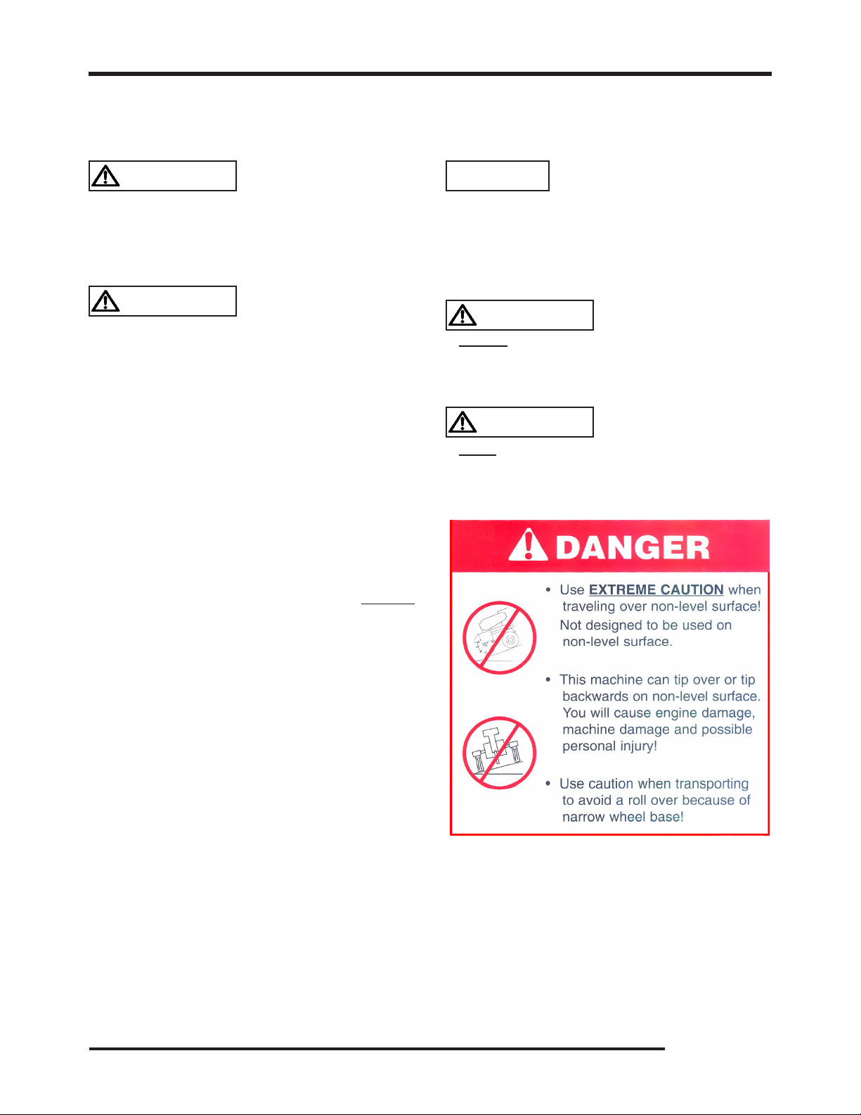
DANGER
DANGER
DANGER
DANGER
WARNING
WARNING
Diesel engine exhaust and some of its
constituents are known to the State of
California to cause cancer, birth defects,
and other reproductive harm.