Band Shoppe LONG RANGER IV User manual

FIRST PLACE STARTS HERE™ PH 800.457.3501 • BANDSHOPPE.COM
UPDATED 10.07.2004
LONG RANGER IV: OPERATING INSTRUCTIONS & TROUBLESHOOTING GUIDE
1
Thank
you for selecting the Long Ranger portable wireless sound system. This unique design combines a rechargeable power supply, a
high-power amplifi er and loudspeaker and high quality VHF wireless microphone into a single compact assembly. The design has evolved
with numerous refi nements since its fi rst predecessor was introduced in the early 1980’s to serve public address applications indoors and
outdoors, with the ruggedness and reliablity needed for professional use.
A single Long Ranger provides enough output power to cover surprisingly large outdoor areas as a stand-alone unit. Versatile options
and accessories expand the use of the Long Ranger to handle unusual coverage areas with the addition of external loudspeakers.
Optional accessories also include an additional wireless microphone, hard-wired microphone, tape recorder, CD player, etc. Two Long
Ranger systems can be interconnected with a single cable to allow multiple microphones and other audio sources to use both systems
simultaneously, operating together as though they are a single sound system.
TABLE OF CONTENTS
IN
TRODUCTION
.......................................................................................................................................................................................
1
GENERA
L TECHNICAL DESCRIPTION
.........................................................................................................................................................
2
RECHARGEABLE BATTERIES AND EXTERNAL POWER SOURCES
..................................................................................................................
2
CONTROLS AND FUNCTIONS
....................................................................................................................................................................
3
CONTROL PANEL
......................................................................................................................................................................
3
FRONT PANEL
..........................................................................................................................................................................
4
SYSTEM SETUP RULES
.............................................................................................................................................................................
5
INITIAL EQUIPMENT ADJUSTMENTS
..........................................................................................................................................................
5
USING ADDITIONAL SPEAKERS
.................................................................................................................................................................
7
ADDING A SECOND WIRELESS CHANNEL TO YOUR LONG RANGER
..............................................................................................................
8
INITIAL ADJUSTMENTS TO THE ADD-ON RECEIVER SYSTEM
.......................................................................................................................
9
SPECIAL NOTE TO DUAL-CHANNEL USERS
.................................................................................................................................................
9
MULTIPLE LONG RANGER SYSTEMS
........................................................................................................................................................
10
MICROPHONE CHOICES
.........................................................................................................................................................................
11
ACCESSORIES AND REPLACEMENT PARTS
..............................................................................................................................................
12
SPECIFICATIONS
...................................................................................................................................................................................
12
TROUBLESHOOTING
...............................................................................................................................................................................
13
SERVICE AND REPAIR
............................................................................................................................................................................
14
RETURNING UNITS FOR REPAIR
.............................................................................................................................................................
14
WARRANTY
...........................................................................................................................................................................................
15
INTRODUCTION

FIRST PLACE STARTS HERE™ PH 800.457.3501 • BANDSHOPPE.COM
UPDATED 10.07.2004
LONG RANGER IV: OPERATING INSTRUCTIONS & TROUBLESHOOTING GUIDE
2
GENERAL TECHNICAL DESCRIPTION
The
standard
Long Ranger Portable Wireless Sound System consists of a combination wireless receiver/amplifi er/speaker with a rechargeable
battery pack, a belt-pack or plug-on transmitter and a microphone. Optional microphones, extension speakers and add-on equipment for a
second wireless channel are available.
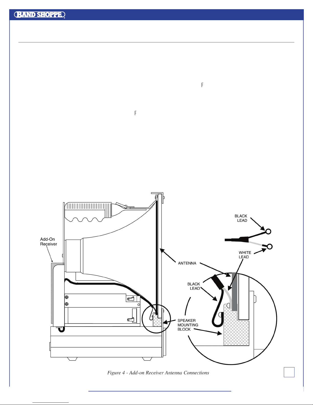
The Long Ranger features a VHF wireless microphone system with a transmitter-to-receiver operating range of up to 750 feet. The receiver is
designed for high selectivity to prevent interference from other transmitted radio signals. The system is designed and constructed for rigorous
portable use with the antenna integrated into the horn speaker to eliminate damage.
The Long Ranger will operate from 8 to 12 hours from the “on-board” rechargeable battery pack before recharging is necessary. The actual
operating time is dependent upon the type of usage...intermittent or continuous. The unit can also be operated from an external 12 Volt DC
source or an AC wall outlet.
The amplifi er produces 33 Watts, RMS, into the 8 Ohm horn speaker. The sound output will cover an area the size of a football fi eld under
average outdoor conditions. Several Long Rangers can be easily connected together to provide even greater area coverage.
RECHARGEABLE BATTERIES AND EXTERNAL POWER SOURCES
The built-in
battery
pack in the Long Ranger is charged by plugging the DCR15/2AU charger into the jack labeled DCR15/2AU CHARGER on the
control panel. Connect the charger into a standard 110 or 220 Volt AC outlet. (The DCR15/2AU charger can be operated from 110/220V, 50/60Hz.)
The green lamp beneath the jack will light as long as the batteries are charging. When the batteries are almost completely charged the green
charging light will go out. You may leave the charger plugged in after the green light has gone out with no danger of damage to the system. In
fact, we recommend charging the system whenever it is not in use, then the system will always be “ready to go”.
The DCR15/2AU charger can charge the batteries in as little as 2
½
hours. If the unit is completely run down, it may require as much as 6 hours
to fully charge the batteries. Leave the charger plugged in at least until the green lamp below the CHARGER jack goes out.
NOTE: In the case of severely discharged batteries (this can happen if the Long Ranger has been left on constantly for several months),
it may be neccessary to charge the unit for a much longer time. Up to 10 days charge time is not uncommon in these circumstances.
The DCR15/2A charger is capable of charging the batteries and running the Long Ranger in normal operation at the same time. The time required
to fully recharge that batteries will be longer if the unit is being used while charging the battery pack.
CAUTION!
USE ONLY THE SUPPLIED DCR15/2A CHARGER
DO NOT USE THE OLDER CH40 CHARGER IN THE NEW LONG RANGER 4. THE CH40 WILL NOT CHARGE
THE BATTERIES IN THE LONG RANGER 4 AND WILL BE DAMAGED IF USED.
The L
ong Ranger can be operated from an external 12 Volt DC source such as an automobile battery or, most commonly, from the cigarette
lighter receptacle in your vehicle. To use an external power source it must be connected into the 12V DC POWER INPUT jack on the Long Ranger
front panel. CAUTION–Make sure you comply with the polarity markings on the jack. The correct plug for making the connection is a Radio
Shack 274-1567 size K coaxial DC power plug. Radio Shack also stocks cigarette lighter plugs (with built-in fuse) and cords to construct a
suitable assembly.

FIRST PLACE STARTS HERE™ PH 800.457.3501 • BANDSHOPPE.COM
UPDATED 10.07.2004
LONG RANGER IV: OPERATING INSTRUCTIONS & TROUBLESHOOTING GUIDE
3
CONTROLS AND FUNCTIONS: CONTROL PANEL
WIRELESS MICROPHONE VOLUME
Turns unit power on and off and also functions as the volume control for the internal wireless receiver.
POWER
A
red LED that lights when unit power is on.
RF
A
green LED that lights when the companion transmitter is turned on and there is suffi cient signal for good system operation. Internal circuits
monitor both signal level and interference levels and decide if the transmitted signal is strong and “clean” enough for satisfactory operation.
If not, the green RF LED will go out and the receiver will mute the audio (“squelch”), turning off the sound output. This action is automatic and
requires no user adjustments.
MOD LEVEL
The
red and green MOD LEVEL LEDs continuously indicate the modulation level (audio level) of the received signal from the transmitter and are used
when making intial adjustments to the transmitter.
MIC
This
connector is a standard ¼” phone jack and is used for plugging in the cord from a low impedance dynamic microphone.
LINE
This
mini jack is used for connecting high level, high impedance outputs from tape decks or other amplifi ers. It also may be used for connecting the
“earphone” output from portable cassette players.
AUXILIARY INPUT VOLUME
Adjusts
the volume of the MIC and LINE inputs.
AUX IN/OUT
An
RCA phone jack that functions both as a line level input and line level output. This “omnibus” jack is primarily used for interconnecting several
Long Rangers together for simultaneous operation. This jack can also be used with a tape deck to either record from or play back into the Long
Ranger. When used with a tape deck or other audio source, the sound output level must be controlled by the volume control on the tape deck since
there is no volume control on the Long Ranger for the AUX IN/OUT jack. When an external device is connected to this jack, the loudness of the Long
Ranger will usually be reduced.
DCR15/2AU CHARGER
A
special jack used for connecting the charger when charging the battery pack. The green LED located under the jack lights when the batteries are
charging. This LED automatically goes out when the batteries are almost fully charged.
12V DC OUTPUT
A
special jack used to supply power to the Add-On receiver when that option is installed.

FIRST PLACE STARTS HERE™ PH 800.457.3501 • BANDSHOPPE.COM
UPDATED 10.07.2004
LONG RANGER IV: OPERATING INSTRUCTIONS & TROUBLESHOOTING GUIDE
4
CONTROLS AND FUNCTIONS: FRONT PANEL
12V DC EXT POWER
A
special jack used to connect an external 12 Volt DC source to the unit to substitute for the “on-board” battery pack. It is most commonly used for
connecting the Long Ranger to a vehicle cigarette lighter or 12V DC auxillary receptacle. When an external power source is connected to this jack,
the on-board battery pack is automatically disconnected. Connectors and power supply cables are available from electronics parts suppliers such
as Radio Shack.
EXTERNAL 8 OHM SPEAKERS
Two
jacks which are used to connect external 8 ohm loudspeakers such as the Lectrsonics H300 re-entrant horn. This jack can also be used to power
other brands of loudspeakers, but be sure that the speaker has a rated impedance of 8 ohms. The left-hand jack disconnects the built-in horn when
the plug is inserted. The right-hand jack will operate the internal horn along with the external speaker. The effi ciency of different makes and models
of speakers varies signifi cantly. Even though two different speakers are both rated at 8 ohms, their loudness could be quite a bit different. The other
specifi cation to compare when considering the use of another speaker is the effi ciency rating. The horn built into the Long Ranger is rated at 107 dB
SPL (sound pressure level) at one meter with a one watt input. Check this specifi cation on the speaker you are considering. A speaker with a lower
“dB’ number will not be as loud as the horn built into the Long Ranger.

FIRST PLACE STARTS HERE™ PH 800.457.3501 • BANDSHOPPE.COM
UPDATED 10.07.2004
LONG RANGER IV: OPERATING INSTRUCTIONS & TROUBLESHOOTING GUIDE
5
SYSTEM SETUP RULES
This
section includes some basic rules that will ensure trouble-free operation of your Long Ranger system.
1.
Make
sure the transmitter battery is good, or better yet, new.
2.
Charge
up the battery pack in the Long Ranger fully before you use the system. Charge until the green charging lamp underneath
the CHARGER jack on the Long Ranger control panel goes out.
3.
Set
up the system so that the Long Ranger is as far from large metal surfaces as possible. Metal surfaces
under
the unit
(such as pickup truck cabs or a car top) are generally no problem but large metal surfaces
alongside
the Long Ranger may
interfere with wireless reception.
4.
If
you have more than one transmitter
on the same frequency
, turn on only one transmitter at a time. You cannot use two transmitters
at the same time with a single Long Ranger. You will need to “alternate” back and forth between the transmitters. Failure to do so will result
in an obnoxious whining sound from the system, and the audio will probably not be understandable. “Add-on” wireless mic systems are
available separately to permit operation of two transmitters simultaneously through a single Long Ranger.
5.
Use
the minimum volume that will enable everyone to hear. It doesn’t have to be loud to be heard.
6.
Always
turn the power off before connecting or disconnecting external speakers.
7.
The
Long Ranger should be elevated for best coverage. The unit should ideally be at least 2 feet higher than the audience. For example,
with an audience standing on fl at ground, the number of people that can hear clearly will
double
if you raise the unit from 5 feet above
the ground to 7 feet ablove the ground.
8.
During
actual operation the Long Ranger should be located at least 20 feet away from the person using the microphone and aimed so
that the sound from the speaker is directed toward the audience and away from the microphone. This will reduce feedback problems.
“Feedback” is a loud squealing sound coming from the speaker when the volume is too high or the microphone is too close to the Long
Ranger. Feedback is generally much more of a problem when using lavalier (lapel) type microphones. The headset models are recommended
for use with the Long Ranger system since they place the microphone pickup much closer to your mouth, which increases the loudness of the
Long Ranger before feedback occurs.
INITIAL EQUIPMENT ADJUSTMENTS
This
section covers the initial adjustments to the transmitter and Long Ranger that must be made before the system is placed into operation.
The step-by-step procedures are listed in the order in which they should be performed:
1.
Turn
Long Ranger power on – The POWER lamp lights.
2.
Rotate
both
volume controls counter-clockwise to their minimum settings.
3.
Position
yourself
behind
the Long Ranger so that the sound from the speaker will be directed away from the microphone.
4.
Plug
your microphone into the transmitter. Rotate the plug clockwise to make sure the connection is locked.
5.
Turn
the transmitter power on and verify that the red lamp on it lights. If the lamp is very dim or does not light, replace the battery.
6.
Observe
that the green RF lamp on the Long Ranger control panel is lighted. This verifi es that the unit is receiving a usable
signal from the transmitter.
7.
Position
the microphone on yourself (or other user) in the location it will be during actual operation. If you are using the single-band
or dual-band headset microphone, turn the white knob on the headset fully clockwise (maximum). The HM162 over-ear microphone
should be positioned so that the pickup element is just to the left of the mouth, so that breath pops do not strike the capsule. Lavalier
microphones should be positioned high on the chest or collar, as close to the mouth as possible to minimize the possibility of “feedback.”
Table of contents