Banda ICE 2000W rms User manual

w w w . b a n d a a u d i o p a r t s . c o m
Made in Brazil
Versão: Abril / 2014
COSTUMER SERVICE:
5 5 ( 1 9 ) 3 8 4 4 - 7 1 7 3 - ( 1 9 ) 3 8 4 4 - 7 4 6 5 - ( 1 9 ) 3 8 4 4 - 4 9 2 3 •
BANDA@BANDAAUDIOPARTS.CO M
WARRANTY
Banda Audioparts warrants this equipment to be free of all defects in material and workmanship
for a period of 12 months from the date of purchase
Within the period of this warranty, Banda Audioparts will repair or replace, free of charge, any
part proving defective in material or workmanship.
Warranty Exclusions:
1. Damage resulting from misuse, abuse, accident, alterations or improper installation;
2. Damage resulting from installation in surfaces subjected to high levels of vibration;
3. Corrective work necessitated by repairs made by anyone other than a Banda Audioparts authorized service
technician;
This warranty does not cover shipping costs.
The defective equipment must be shipped to the factory or to an authorized service center
Rua Hum, 188 - Jardim Santa Terezinha II - Paulínia - SP - Brazil -
CEP: 13148-133
Banda Audioparts reserves the right to change the product and its specifications at any time without prior notice.
Note:Permanent Technical Support
After the warranty expires, Banda Audioparts will continue to provide extensive technical assistance directly or
through its network of authorized service, charging, however, the repair services and replacement of components
Warning: Continuous expose to sound pressure levels over 85dB may cause permenent hearing loss.
REGISTRATION DATA
Name:
Invoice: Date: Phone:
Address:
Shop: Phone:
12
I N S T R U C T I O N M A N U A L
I C E 2 0 0 0 W r m s
I C E 2 5 0 0 W r m s
I C E 3 5 0 0 W r m s

INDEX
TECHNICAL SPECIFICATION
02 .......... • ICE 2000 • ICE 2500 • ICE 3500 Technical Specification
03 .......... • ICE 2000 • ICE 2500 • ICE 3500 Technical Specification / Front Panel
04 .......... • ICE 2000 • ICE 2500 • ICE 3500 Power Supply Section
04 .......... • ICE 2000 • ICE 2500 • ICE 3500 Signal Input and Power Output Section
Subsonic and Crossover Controls 04 .......... • ICE 2000 • ICE 2500 • ICE 3500
04 .......... • ICE 2000 • ICE 2500 • ICE 3500Clip Indicator
05 .......... • ICE 2000 • ICE 2500 • ICE 3500General Technical Specification
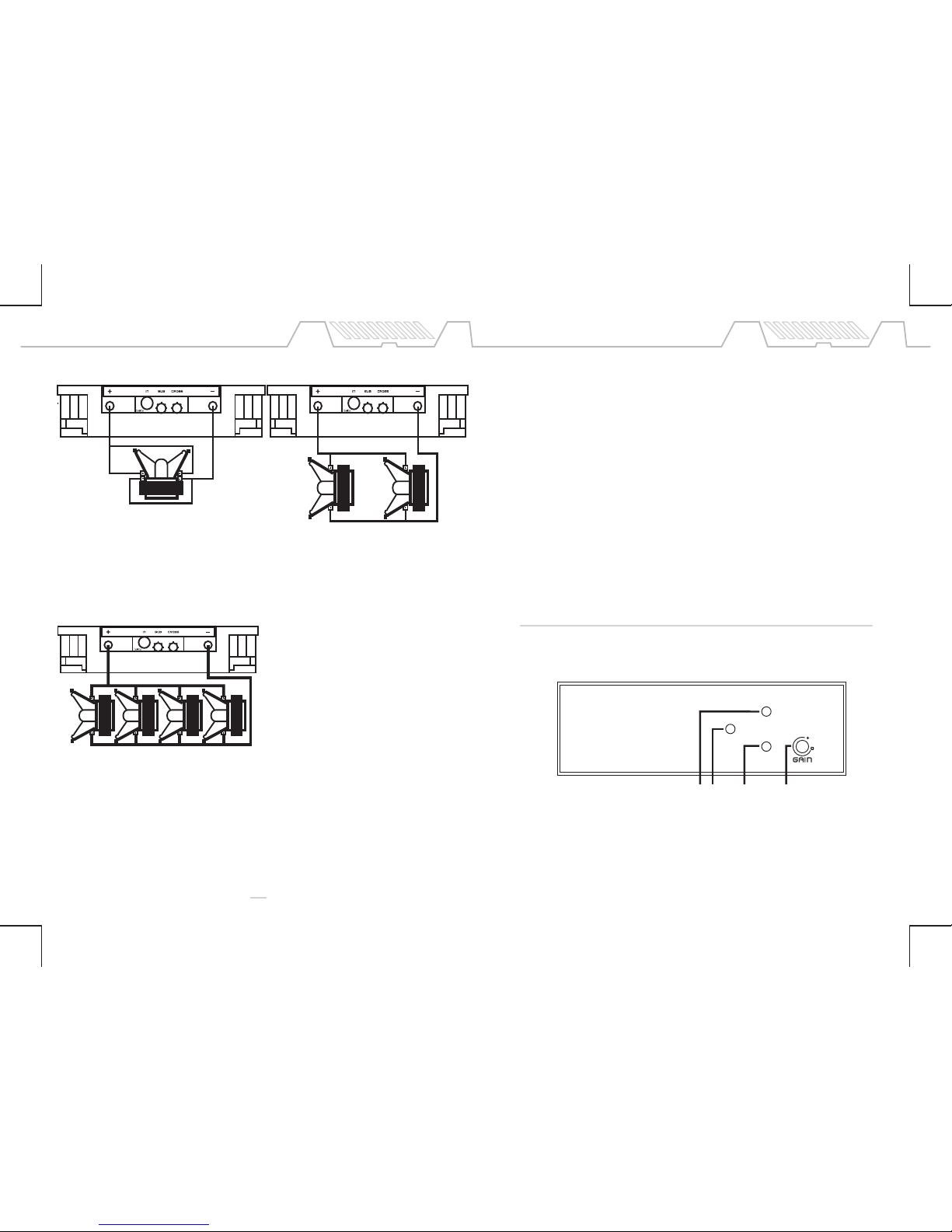
Connection Example 06 .......... • ICE 2000 1 Ohm
Connection Example 07 .......... • ICE 2000 2 Ohms
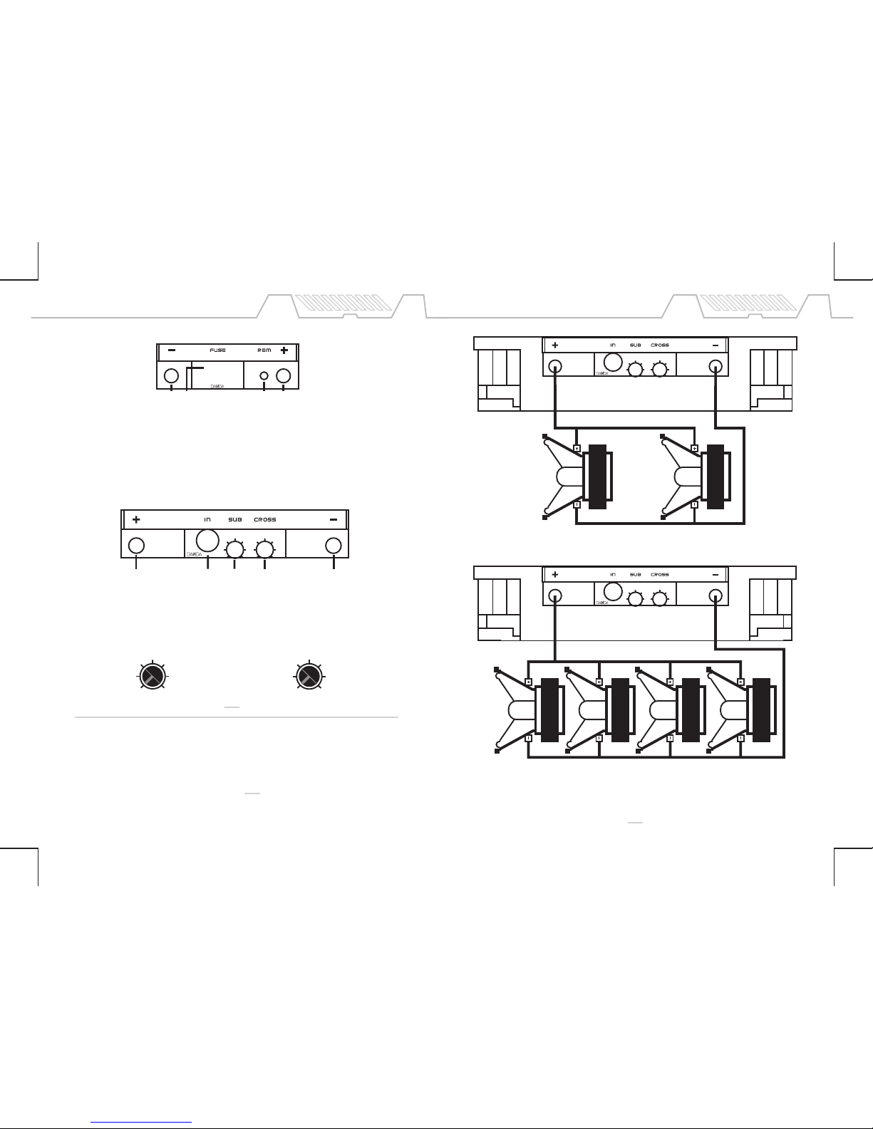
08 .......... • ICE 2500 1 Ohm Connection Example
Connection Example 09.......... • ICE 2500 2 Ohms
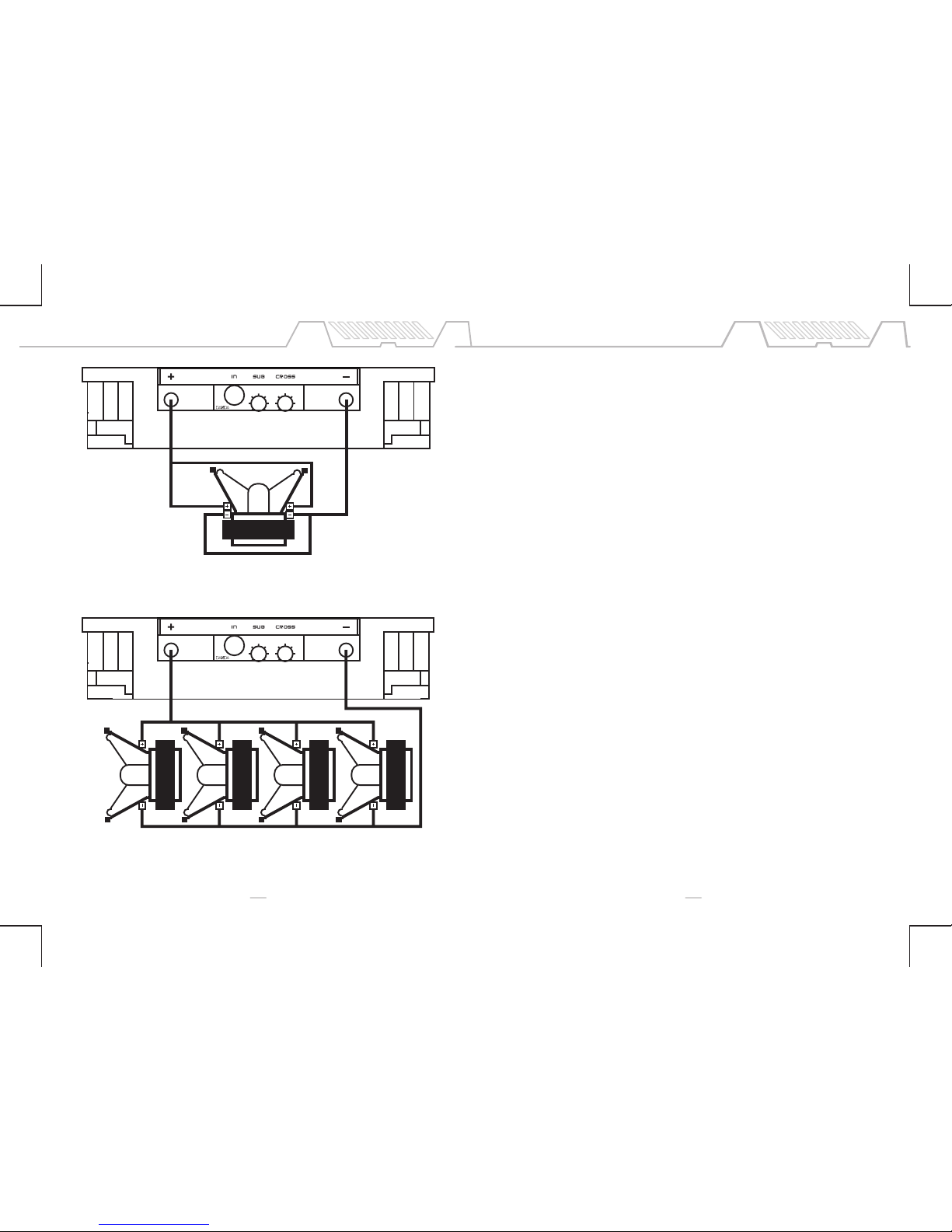
10 .......... • ICE 3500 1 Ohm / 2 Ohms Connection Example
11 .......... Protection System and Troubleshooting
12 .......... Warranty
02 11
Short Circuit protection:
If short circuit is detected in output terminals, the amplifier shuts down an the red LED lights up. The equipment
must be turned off, solve the short circuit problem and turn the equipment on again. If the problem is solved,
the blue LED must light up. If the load impedance is lower than the amplifier specification, the equipment may
trigger the short circuit protection.
Low Voltage Protection:
When battery voltage is lower than 9Vdc, the amplifier will shut down and the yellow LED will blink until the
equipment is restarted.
Power Supply Inverted Cable Protection:
If the power supply cables are connected inverted, the internal fuse will blow.
Troubleshooting:
Protection triggered
1. Check if the internal fuse is blown. If so, replace it with a same current rate fuse.
(80A) ICE 2000Wrms, (100A) ICE 2500Wrms e (150A)ICE 3500Wrms.
2. Check if there is short circuit in the output terminals. To do it, turn off the amplifier, disconnect all speakers
and the input RCA cable and wait about 20 seconds. Turn the amplifier again and if the blue LED lights up, the
amplifier is operating normally.
3. Check if any speaker is presenting short circuit or the total impedance load is lower than the amplifier
specification.
4. Check if there is enough current in battery to supply the amplifier and if the cables are capable of conduct that
current.
Output Noise
1. Check if there is loose connection in signal input or in the RCA cable.
2. Check if there is ground connection in the radio/cd RCA output.
3. Check if RCA cables are wired separated from the power cables.
4. Check if the +12Vdc that powers the amplifier is coming directly from the battery.
5. Check if ground cable is connected in car chassis as near as possible of the amplifier.
6. Both radio/cd and amplifier must be firmly connected to car chassis ground to avoid noises and voltage
fluctuations at amplifier output.
PROTECTION SYSTEM AND TROUBLESHOOTING
• Operation Topology: Full Bridge Class D
• Variable LINKWITZ-RILEY Active Crossover: 30Hz - 20kHz (12dB/octave)
• Input Impedance: 47kohms (ICE 2000, ICE 2500 e ICE 3500)
• Frequency Response: 18hz - 20kHz (ICE 2000, ICE 2500 e ICE 3500)
• Variable Subsonic Filter: 30Hz - 120Hz
• Clip Indicator
• THD < 0.33%
• SNR > 74.3dB
• Damping Factor > 100
• Input Sensitivity: 0,1 - 1Volt
• Stand-by current consumption (remote On): 1.9A (average).
• Gain Control
• Differential Input Circuit
• Cooling Fan In Models ICE 2500 and 3500
• ICE 2000, 2500 e 3500:
Dimensions: 12.1" L x 2.5" H x 10.1" W
Weight: ICE 2000 / ICE 2500: 11.1lb
ICE 3500: 12.1lb
*These values are typical and may present some minor variation.

03
TECHNICAL SPECIFICATION - ICE 2000-2500-3500
• Output ICE 2000 1ohm / 2ohms:
1 channel 2000Wrms 1ohm / 12.6Vdc, 1 channel 2000Wrms 2ohms / 12.6Vdc,
1 channel 2500Wrms 1ohm / 14.4Vdc or 1 channel 2500Wrms 2ohms / 14.4Vdc or
1 channel 1400Wrms 2ohms / 12.6Vdc. 1 channel 1200Wrms 4ohms / 12.6Vdc.
Current draw at full power (average music program): 108A*
•Output ICE 2500 1 ohm / 2 ohms:
1 channel 2500Wrms 1ohm / 12.6Vdc, 1 channel 2500Wrms 2ohms / 12.6Vdc,
1 channel 3200Wrms 1ohm / 14.4Vdc or 1 channel 3200Wrms 2ohms / 14.4Vdc or
1 channel 1500Wrms 2ohms / 12.6Vdc. 1 channel 1500Wrms 4ohms / 12.6Vdc.
Current draw at full power (average music program): 121A*
• Output ICE 3500 1 ohm / 2 ohms:
1 channel 3500Wrms 1ohm / 12.6Vdc, 1 channel 3500Wrms 2ohms / 12.6Vdc,
1 channel 4500Wrms 1ohm / 14.4Vdc or 1 channel 4500Wrms 2ohms / 14.4Vdc or
1 channel 2100Wrms 2ohms / 12.6Vdc. 1 channel 2100Wrms 4ohms / 12.6Vdc.
Current draw at full power (music program): 180A*
*Equivalant to current draw with resistive load and sinusoidal signal at half power.
10
CONNECTION EXAMPLES ICE 3500 1 ohm / 2 ohms
NOTE: These are basic projects, just given as examples.
TECHNICAL SPECIFICATION - ICE 2000 - 2500 - 3500
123 4
on
Clip
LOW Batt
short
fuse
Front panel view
1. • Blue LED: On
2. • Red LED: Blinking - output clipping (distortion) / Constant - output short circuit
3. • Yellow LED: Blinking - low voltage battery / Constant - Fuse blown or missing
4. Gain control
1 ohm model:
2+2ohms 3500Wrms Subwoofer
coils wired in parallel
resulting in 3500Wrms@1 ohm.
2 ohms model:
2 - 4ohms 1750Wrms woofer
each, wired in parallel
resulting in 3500Wrms@2ohms.
2 ohms model:
4+4ohms 3500Wrms Subwoofer
coils wired in parallel
resulting in 3500Wrms@2 ohms.
1 ohm model:
4 - 4ohms 875Wrms woofer
each, wired in parallel, resulting in
3500Wrms@1ohm.
2 ohms model:
4 - 8ohms 875Wrms woofer
each, wired in parallel, resulting in
3500Wrms@2ohms.
Note: Considering the frequency response
18Hz - 20kHz(ICE 2000,ICE 2500 e ICE 3500) these
equipment are capable of playing all music range,
therefore suited for use with subwoofers, woofers mids
and tweeters.

04
TECHNICAL SPECIFICATION - ICE 2000 - 2500 - 3500
09
CLIP INDICATOR - ICE 2000 - 2500 - 3500
The red LED lights up when the amplifier output is distorting. As long as the speakers used are capable
of handle the total output power this LED can eventually blink but if it holds still it means too much
distortion in the output and this can damage the speakers and the amplifier. In this case, turn down
the head unit volume.
Power supply section - ICE 2000, ICE 2500 and ICE 3500.
1. Negative power input (ground): connect to car chassis.
2. Protection fuse: • 80A (ICE 2000Wrms)• 100A (2500Wrms) • 150A (ICE 3500Wrms).
3. Remote input: connect to radio/cd remote output.
4. Positive power input (+12Vdc): connect to baterry positive terminal.
234
1
Crossover Control
30
35
40 50 70
100
120Hz
Sets the beggining of response
30
60
100 220 540
2000
20kHz
Sets the end of response
Subsonic Control
Signal input and power output section.
1. Positive speaker output
2. Signal input (RCA)
3. Subsonic control
4. Crossover control
5. Negative speaker output
1 2 3 4 5
2- 4ohms 1250Wrms subwoofers or woofers each
wired in parallel, resulting in 2500Wrms@2ohms.
4 - 8ohms 625Wrms woofers each, wired in
parallel, resulting in 2500Wrms@2ohms.
CONNECTION EXAMPLES ICE 2500 2 ohms
NOTE: These are basic projects, just given as examples.

05
08
GENERAL TECHNICAL SPECIFICATION
Important notes:
• Use 4AWG (ICE2000 and ICE2500) and 2AWG (ICE3500) power cables for both GND and +12Vdc.
• Do not use impedance load lower than the amplifier specification. This can damage the equipment.
• Use wire solder for tinning the cable end for better electrical contact. Loose electrical connection can
cause malfunction, heating and even fire
• The GND connection must be as short as possible, using adequate wire terminal firmly connected to
a clean, paint free spot at the car chassis.
• If more than one amplifier is used, provide adequate individual wiring for each one.
•If using two amplifiers to play a single unit double coil speaker make sure to use the same input signal
and adjust the control gain in both units precisely at the same value.
• When the internal fuse blow, the yellow LED will blink for a moment and than keep turned on.
•There is no current consumption when the remote input is off.
• If using power supply to power the amplifier, it must be capable of supply between 12.6 – 14.4Vdc
with at least the amplifier maximum current value and maximum output variation (Vripple) of 10%.
CONNECTION EXAMPLES ICE 2500 1 ohm
4 - 4ohms 625Wrms woofers each, wired in
parallel, resulting in 2500Wrms@1ohm.
2+2ohms Subwoofer
2500Wrms
coils wired in parallel
resulting in
2500Wrms@1 ohm.
NOTE: These are basic projects, just given as examples.

07
06
2+2ohms 2000Wrms
subwoofer, coils
wired in parallel,
resulting in
2000Wrms@1 ohm.
4 - 4ohms 500Wrms woofers each, wired in
parallel, resulting in 2000Wrms@1ohm.
CONNECTION EXAMPLE ICE 2000 1 Ohm
4+4ohms 2000Wrms
subwoofer, coils
wired in parallel,
resulting in
2000Wrms@2 ohms.
2 - 4ohms 1000Wrms woofer each
wired in parallel, resulting in
2000Wrms@2ohms
CONNECTION EXAMPLE ICE 2000 2 Ohms
NOTE: These are basic projects, just given as examples.
This manual suits for next models
2
Table of contents
Other Banda Amplifier manuals