Light Weight Taut Wire Mk 14B Operation Manual
9
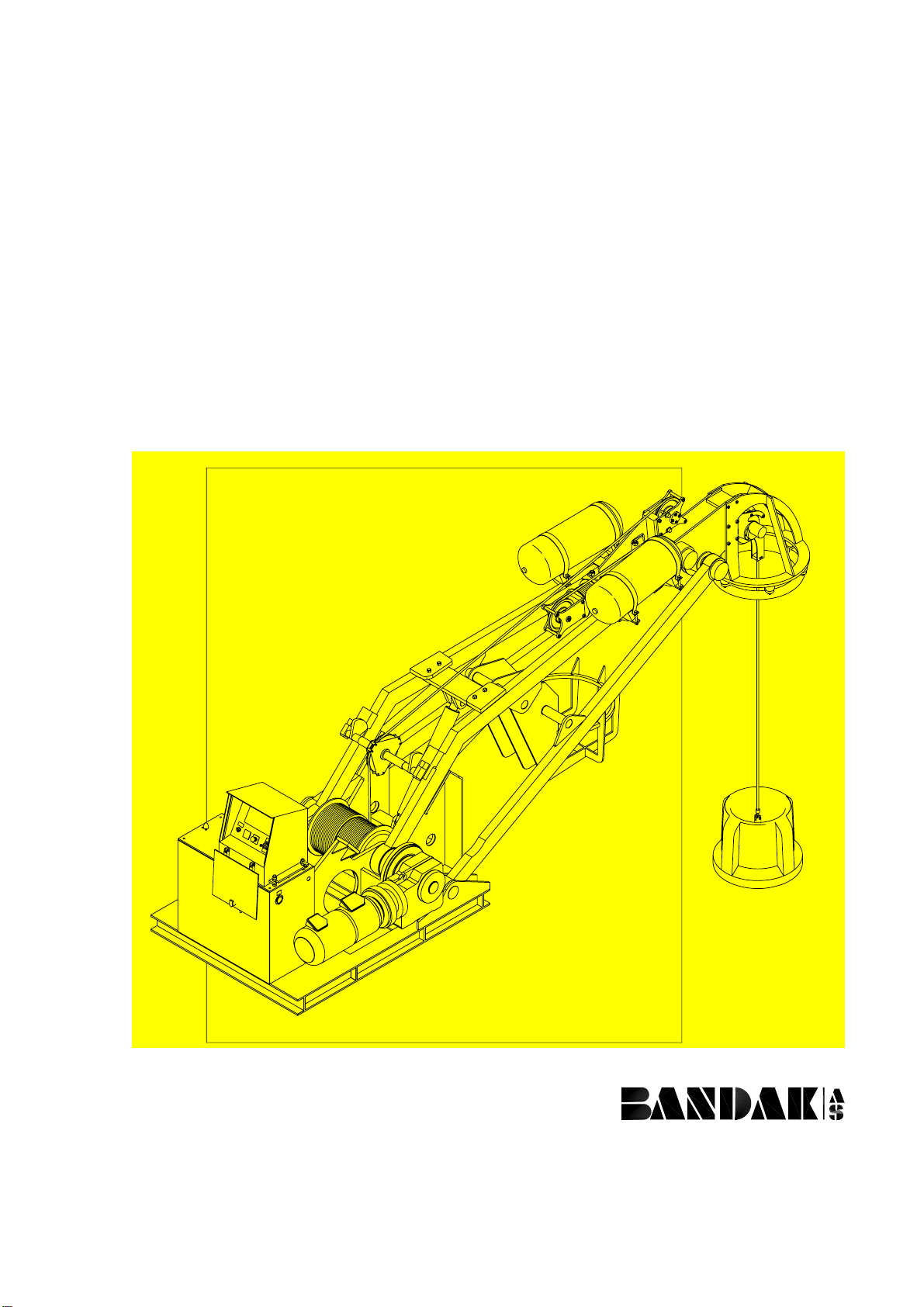
4TECHNICAL DESCRIPTION
4.1 Principle of Operation
The purpose of the Taut Wire is to give accurate input data, related to
vessel movement, to the vessel data processing system to calculate
vessel position corrections.
The Taut Wire system is fundamentally electro-hydraulic-pneumatic
and requires electrical and air supply from the vessel.
The wire rope, although thin to reduce the "offsets" caused by
underwater current disturbance, is strong enough to heave the weight
with a safety factor of 400 percent. Control of the system is effected
from either of two control panels; main control panel (local) or optional
bridge control panel (remote).
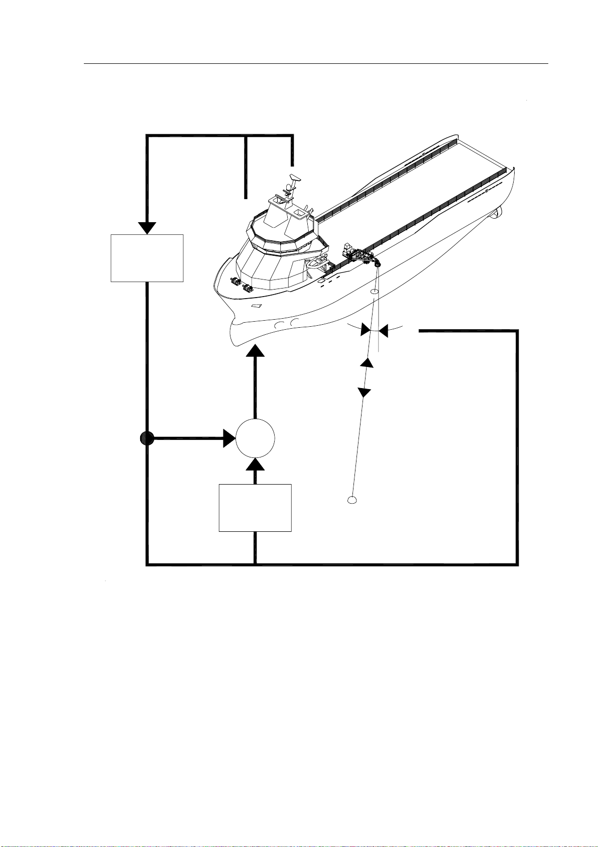
The wire rope is tightened against the depressor weight (on the seabed)
with a constant tension by means of a pneumatically and servo electric
"mooring" control system. Any movement of the vessel in either or
both of the X (alongship) or Y (beam) co-ordinates, will cause a
deviation of the tensioned wire rope from the vertical. This deviation
activates potentiometers mounted in the gimbal (sensor) head and
produce changes of analogue data directly proportional to the X-Y
inclination of the gimbal head.
The analogue wire length measurement is obtained from a measuring
device driven by the moving wire.
The DP system contains an accurate model of the dynamics of the
vessel which simulates the vessel's response to various forces e.g. wind,
wave and current disturbance.
Deviations in the specified position of the vessel (detected by changes
above analogue input parameters) will be processed by the software
model to generate appropriate corrective commands to the vessel's
propeller and rudder system.