B&G h1000 pilot User manual

h1000 system
user manual
HB-1000D-02 English
WARNING!
Use of solvent based or chemical
cleaners on displays will result in
damage and invalidate your
warranty.

introduction h1000
Page 2

h1000 introduction
Page 3
overview
Congratulations on your purchase of the h1000 System from B&G. The h1000 navigation system
combines clever thinking with incredibly simple operation, and represents B&G’s commitment to
providing customers with the finest marine navigation systems. The h1000 is a fully expandable
integrated system of Pilot, Instrument and Chart Plotters offering a major advance in display
flexibility. You can access any information from any display unit, so even one display unit can do
everything providing the sensors are in the system.
Before you begin using your new h1000 System, please take the time to read this manual to help
you achieve the full potential from your new system.

introduction h1000
Page 4
certification
warnings and precautions:
WARNING:
DO NOT USE AN ALCOHOL BASED CLEANER ON THIS DISPLAY.
Note:
This equipment generates, uses, and can radiate radio frequency energy and, if not installed and
used in accordance with the instructions, may cause harmful interference to radio
communications. However, there is no guarantee that interference will not occur in a particular
installation. If this equipment does cause harmful interference, the user is encouraged to try to
correct the interference by relocating the equipment or connecting the equipment to a different
circuit. Consult an authorised dealer or other qualified technician for additional help if these
remedies do not correct the problem.
This device meets requirements for CFR47 Part 15 of theFCC limits forClass B equipment.
The h1000
meets the standards set out in European Standard EN 60945: 1997 IEC 945: 1996 for
maritime navigation and radiocommunication equipment andsystems.
During the manufacturing process, an anti-mist coating is applied to the inside of the display
window, however, undercertain atmospheric conditions, asmall amount of condensation may form
on the window of the instrument display, this will not harm the unit and should clear after a short
period once the instrument has been switched on
The h1000 contains no user-serviceable parts. Repairs should only be made by an authorised
service centre. Unauthorisedrepairs or modifications will invalidate your warranty.
trademarks
All rights reserved. No part of this manual may be reproduced or transmitted in any form or by any
means including photocopying and recording, for any purpose without the express written
permission of B&G.
Information in this document is subject to change without notice. B&G reserves the right to change
or improve its products and to make changes in the content without obligation to notify any person
or organisation of such changes.
B&G, and h1000 are all trademarks of Brookes & Gatehouse Ltd. and may not be used without the
express permission of B&G.

h1000 contents
Page 5
contents
overview 3
warnings and precautions 4
trademarks 4
contents 5
system overview 7
display overview 8
light controls 8
switching on and off 9
switchingon 9
default data pages 9
examples of the default data pages 9
switchingoff 9
default factory settings 10
changing screen format 10
screen formats 10
changing page data 10
graphical pages 11
graphical pages 11
track screen 11
depth 11
pilot display 11
main menu 12
timer 12
memories 13
compass 13
reset trip log 13
alarms 13
memories 14
alarms 14
lighting 14
calibrations 15
depth calibration 16
speed calibration 17

contents h1000
Page 6
contents
wind calibration 19
compass calibration 21
system set-up 23
compass function 24
alarms 25
alarm conditions 25
errorconditions 25
data failure 26
technical specifications 27
installation 28
precautions 28
panel mounting 28
electrical connections 29
external connections 29
interface connections 29
connections 29
system expansion 30
pilot features 30
cnd features 30
analogue features 30
system expansion 31
3fd features 31
interface box features 31
system expansion diagram 32
abbreviations 33
warranty 34

h1000 overview
Page 7
system overview
Depth
Sensor
Speed
Sensor
12 Volts
10m Fastnet Cable2m Fastnet Cable
LCD Display
Speed Depth
Interface Box
Masthead Unit
Wind
Interface Box

overview h1000
Page 8
display overview
light controls
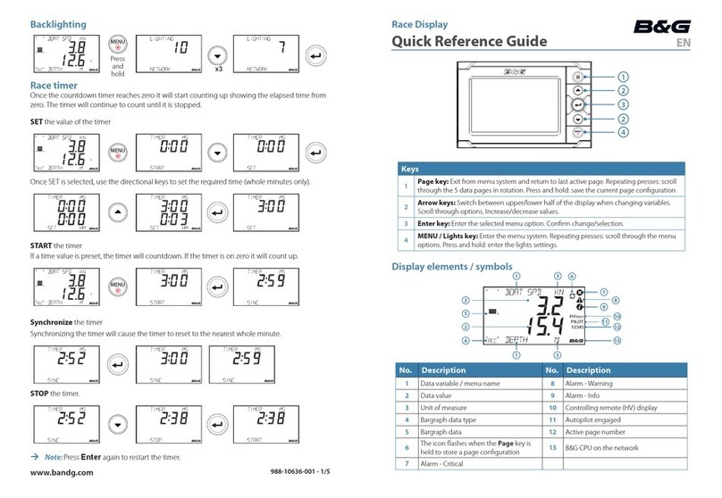
The lighting level can be changed at any time by pressing the LIGHTS key.
This causes the lighting level to cycle in the sequence high - medium -
low - off and then back to high.
The UP/DOWN keys are used to move through the various display pages
and to scroll through options.
Pressing the ENTER key displays the Main Menu, it is also used to select
highlighted items.
Title Line
Data Entr y Fi el d
Highlighted
Menu Item
A
ddi tio nal
commands are
displayed here
OK returns to
previous menu
whe n hi ghlighte d
and the ENTER
key is pressed

h1000 getting started
Page 9
switching on and off
Before switching the
h1000
on, check that the
installation instructions detailed on pages, 28 and 29
have been correctly followed.
switching on
Turning on the 12 Volt power supply to the system you
will be presented with the B&G logo splash screen.
The h1000 will then perform a short self-test
procedure that checks internal memory and displays
any failure detected on the screen.
After a few seconds, the screen will display a data
page, from here you can move through the page
options usingthe UP/DOWN keys.
default data pages
The h1000 displays are pre-programmed with six
default data page formats. These can be accessed by
pressing the UP/DOWN keys. To change the default
data page settings; refer to changing screen format on
Page 7 of this manual. The flexibility of the h1000
system allows for a virtually endless combination of
screen formats to suit individual needs.
Stored Log
▲ ▼ ▲ ▼
▲ ▼
▲ ▼
▲ ▼
▲ ▼
examples ofthe default data pages
switching off
Turning off the 12V d.c. power supply at the breaker
will power off the h1000 System.

getting started h1000
Page 10
default factory settings
Language: English
Speed/Distance Units: Nautical Miles
Depth Units: Metres
Wind Speed Units: Knots
Bearing Reference: Magnetic
DateFormat: Day-Month-Year
Time Reference: UTC (universal time coordinate)
changing screen format
screen formats
The display can be customised for personal
preferences using the Page Contents menu.
changing page data
Pressing the ENTER key from a data page will display the main menu. Select the Page Contents
menu and press ENTER to select the screen format of the data page previously displayed.
Choose one of the pre-defined screen formats using the UP/DOWN keys andthen press ENTER to
select.
Once a screen format has been selected, use the UP/DOWN keys to select which pane you wish to
configure and press ENTER. Use the UP/DOWN keys to scroll through the ‘information displayed’
choices and then press the ENTER key to select. Use the UP/DOWN keys to scroll to the next pane
and press ENTER to select the pane.
Repeat the selection process until you have made a choice for each pane. Use the UP/DOWN keys
to highlight OK and press the ENTER key to save your selections.
To exit this function, use the UP/DOWN keys to highlight OK in the bottom right hand corner of the
screen and press ENTER, you will then be taken back to the Main Menu.

h1000 getting started
Page 11
graphical pages
graphical pages
There are three full-screen graphical pages available
when the appropriate data is on the system.
These pages are viewed by selecting Page Contents
from the Main Menu, and then selecting the Full
Screen option from the Select Format page.
track screen
Available when a GPS is part of the system and
currently navigating to an active waypoint.
The track screen shows the vessel’s position on the
screen as an X, the arrow from the vessel’s position
shows the current course over ground to the next
waypointof the leg.
The relative position of the waypoint is shown as a
circle. The name of the waypoint, the bearing to
waypoint (BTW) and distance to waypoint (DTW)
information are also displayed. The position of this
information depends on the direction of the vessel.
depth
Available when a Depth sensor is part of the system.
Depth is clearly shown in figures in the top half of the
screen.
The histogram in the lower half the screen gives an
impression of the profile of the seabed.
pilot display
Available when a Pilot is part of the system.
This is a read-only repeat of the main page on the pilot
display unit.
The layout of this page will depend on the mode
currently selected by the pilot. Refer to the h1000
Pilot
User manual for more details.

main menu h1000
Page 12
main menu
menu system
From any data page, press the ENTER key to access
the h1000 menu system. The Main Menu will be
displayed.
If no other key is pressed within a period of six
seconds, the display will revert to the previously
displayed data page.
timer
timer
When the Timer is selected from the Main Menu for the first time, the display will show Time to
Start. To adjust the start time, highlight 00 mins and press the ENTER key. Alter the countdown
start time by using the UP/DOWN keys and press the ENTER key to move between the digits.
To start the timer, use the UP/DOWN keys to highlight Start and press the ENTER key when ready.
If the timer is counting down to the start of a race, the Title will remain as Time to Start. When the
timer reaches zero, the title will change to Elapsed Time and continue counting up until Reset is
selected.
The timer function continues to operate even when the timer page is exited. This allows access to
other pages if necessary or perhaps even configure a data page to show the Timer function.

h1000 memories
Page 13
memories
memories
This menu covers various features of the
system in which user-supplied data is stored
for future use.
compass
The com
p
ass memory holds the current course and can be user defined. Port and Starboard courses
are retained and are updated at each ENTERkey press whilst in the Tactical compass page. When OK
is selectedcontrol returns to the Main Menu.
resettrip log
Trip log and Stored log functions can be accessed and displayed from the PageContentsmenu when
a S
p
eed/De
p
th Interface is connected to the system. The tri
p
lo
g
can be reset to zero by hi
g
hli
g
htin
g
Reset trip log from theMemoriesMenu, selecting OK from the dro
p
down box, and then
p
ressin
g
the
ENTER key. Choosing cancel from the drop-down box will exit the function without resettin
g
the tri
p
logvalue.
alarms
Alarm levels for high wind speed, shallow depth, com
p
ass off course and low battery volts can be set
from the Alarms menu.
To set the wind speed alarm, highlight Wind speed from the menu and press the ENTER key. A drop-
down box will appear showing an alarm wind speed value and off. To set the alarm, select the wind
speed value from the drop down box and press the ENTER key. Using the UP/DOWN and ENTER
keys, alter the value to the desired settin
g
. The alarm is now active and will tri
gg
er if the wind s
p
eed
is exceeded. Toswitchoffthe alarm,simplyhighlight off from the drop-down box.
The
p
rocedure for settin
g
the wind s
p
eed alarm is shown on the followin
g
p
a
g
e as an exam
p
le. The
other alarms are set in a similar way.
Note: The low battery alarm is pre-set at 10.5V, and can only be turned ONor OFF.

calibrations h1000
Page 14
memories
alarms
Note: all alarms are set to off when they leave the factory.
When an alarm condition occurs, all dis
p
lays will show an alarm window that identifies the alarm and
displays the current value. If an external alarm is connected to the Universal Interface, this will also
sound. To silence the alarm press the ENTER key on any display.
lighting
The three display lighting levels are controlled by the LIGHTS key in normal operation, but the
exact brightness can be adjusted for each of the three settings from this menu.
The levels are numbered in the order they appear when the key is pressed, and each level can be
set in percentage terms from 00% (minimum) to 99% (maximum).
In addition, this menu page allows for the lighting zone to be set to either local (this display unit
only), or system (the entire system) and is useful when zoning particular displays on the boat. For
example, cockpit display lighting can be isolated from a display located below decks.
Highlighting OK and pressing the ENTER key returns the display to the Main Menu.

h1000 calibrations
Page 15
calibrations
calibration
Calibration values take time and effort to set up and it is often necessary to perform various
manoeuvres with the boat. For this reason, an optional security lock is provided before entry into
the Calibration Menu to prevent accidental resets.
security pin
The security PIN uses a four digit Personal Identification Number or PIN. If security has been
activated, this PIN must be entered if you require the Calibrations Menu.
If you reset the PIN to 0000, security checking is disabled.
security
Security is an option on the Calibrations menu, which allows a new PIN to be set. Once a non-zero
PIN has been set the security checking is enabled, and all subsequent access to the Calibration
Menuis restricted.
Note:
Once the PIN has been entered, the PIN entry screen is automatically by-passed when re-entering
the calibration menu. After a power cycle, the PIN is once again required to enter the Calibration
Menu.
Securit
y
disabled
Security
enabled

calibrations h1000
Page 16
depth calibration
Calibration
Depth
Speed
Wind
Compass
Security OK
Depth
Depth Calibration
Unit
Offset metre
1.20 OK
Unit
Depth Calibration
Unit
Offset metre
1.20
OK
Offset
Depth Calibration
Unit
Offset metre
1.20
OK
Unit metre
foot
fathom
Depth Calibration
Unit
Offset metre
1.20
OK
Offset
depth calibration
Depth calibration allows the units of
measurement and transducer
offset to be adjusted.
depth units
Depth values can be shown in
metres, feet or fathoms. To change
the units, highlight Unit and press
ENTER. Using the UP/DOWN keys,
highlight the desired choice and
press ENTER to memorise.
DEPTH
TRANSDUCER
WATERLINE
(+ VE OFFSET
VALUES)
OFFSET
(VALUE OF
0.0)
KEEL
(- VE OFFSET
VALUES)
KEEL
OFFSET
WATERLINE
OFFSET
depth offset
Offset allows the h1000 to display
depth readings from directly below
the keel or propellers of the boat,
or from the waterline to the seabed.
This makes it much easier to see
how much water clearance is left
beneath the boat.
The offset value to be entered
should represent the distance
between the face of the depth
transducer, and the lowest part of
the boat below the waterline, or the
distance between the face of the
depth transducer and the water
surface.

h1000 calibrations
Page 17
speed calibration
speed calibration
Speed calibration sets the units of measurement, dam
p
in
g
and s
p
eed calibration factor (Refer to the
flow chart detailed on Page 18).
units
Boat speed values can be shown in knots, kph or mph. To change the units, highlight Unit and
p
ress
ENTER. Using the UP/DOWN keys, highlight the desired choice and press ENTER to memorise.
damping
Boat speed damping allows you to slow down the response of speed-readin
g
s in rou
g
her conditions
by ad
j
ustin
g
the dam
p
in
g
value from 0 to 9. For minimum dam
p
in
g
, set the value to 0, for maximum
damping, set the value to 9.
adjustment
S
p
eed ad
j
ustment calibration is necessary to com
p
ensate for hull sha
p
e and
p
addlewheel location on
your boat.For accurate speedandlog readings, it is essential that the paddlewheel is calibrated.
adjustment - auto
This procedure will automatically calibrate the boat s
p
eed and lo
g
readin
g
s, and is the recommended
method for most boats. This
p
rocedure re
q
uires the boat to make consecutive runs, under
p
ower at a
constant speed, over a known distance.
Select two markers that are easily identifiable on the
g
round and on a chart, and where the effects of tidal
flow are at a minimum. Measure and record the distance between the markers on thechart.
It is recommended that three runs are carried out, this accounts for tidal efforts, and im
p
roves accuracy.
However, a time should be selected when thecurrent is ata minimum,i.e. slackwater between tides.
1) From the Speed Calibration Menu, highlightAdjustment , choose auto from the drop-down box, and
then press the ENTER key to confirm.
2) If necessary, adjust theRunLength to correspond with your measured distance and then highlight OK,
and press ENTER to accept.
3) The display will now show Run1 and start will be hi
g
hli
g
hted. Maintainin
g
the boat at your constant
speed, press ENTER when the boat is in line with the start of your measured distance. The dis
p
lay will
nowchange toshowRun1with end highlighted.
4) When the boat is inline with thesecondmarkerof yourmeasureddistance,press theENTER key to
temporarily halt the calibration.Run 2 andstart will now be shown on the screen.
5) Maintaining your constant boat speed, turn the boat through 180°in
p
re
p
aration for yoursecond run
along the measured distance. When the boat is in line with the second marker, press the ENTER key to
resume thecalibration procedure. The display will now showRUN 2 and end will behighlighted.
6) When the boat is in line with the first marker, press the ENTER key.This will tem
p
orarily halt the
calibration procedure.
7) Repeat the procedure detailed above forRun3.
8) Upon completion of Run3, highlight accept all and press ENTER. The system will now automatically
calculate thenew boat speed and update the readings accordingly.
Note: If for any reason during the calibration procedure you wish to abort the calculation, sim
p
ly
highlight abort all and press the ENTER key.

calibrations h1000
Page 18
speed calibration
adjustment – ref
Reference s
p
eed ad
j
ustment, allows for
q
uick and easy calibration of your boat s
p
eed readin
g
s a
g
ainst a
known calibrated source; for example, speed over the
g
roundfrom a GPSor alon
g
side another boat with
a calibrated log.
1) From the
Speed Calibration Menu, highlight Adjustment, select ref from the drop-down box and
press ENTER toselect. Thedisplay will nowshow the ReferenceSpeed page.
2) If Speed Over the Grounddata is available on the system from a GPS, the h1000 will
automatically detect this and display this value on the screen with the message from SOG. To
accept this value, simply highlight the speed value shown, press the ENTER key repeatedly to
scroll past the digits, use the UP/DOWN keys toselect OK and press the ENTERkey.
3) If s
p
eed over the
g
round is not available, sim
p
ly hi
g
hli
g
ht the s
p
eed value and, usin
g
the
UP/DOWN and ENTER keys, adjust the value to the known reference boat speed.
4) Next, highlight OK and press ENTER to complete the operation.
sea temperature units
Sea temperature information can be shown in °cor °f. To change the units, highlight Sea temp and
press ENTER. Using the UP/DOWN keys, highlight the desired choice, and press the ENTER key to
memorise.

h1000 calibrations
Page 19
wind calibration
wind calibration
Wind calibration sets the wind s
p
eed measurement units, dam
p
in
g
, and masthead unit offset. The
masthead unit offset can be adjusted while observing the live apparent wind angle on the same pa
g
e
(Refer to the flow chart detailed on Page 20).
wind speed - units
Wind s
p
eed values can be shown in knots, k
p
h, m
p
h or m/s. To chan
g
e the wind s
p
eed units,
highlight Wind speed from the Calibration Menu and press ENTER. Next, highlight Unit,
p
ress
ENTER and select the desired choice from the drop-down menu. Press the ENTER key a
g
ain to
memorise the setting.
wind speed damping
Wind speed damping allows you to slow down the response of wind speed-readin
g
s in
g
usty
conditions by adjusting the damping value from 0 to 9. For minimum dam
p
in
g
, set the value to 0.
Increase the damping value if the readings are too unstable in rough weather.
wind angle - calibration
Accurate wind an
g
le readin
g
s re
q
uire the masthead unit to be installed facin
g
forward and as close
to the centre line of the boat as
p
ossible. However, this is not always
p
ossible, so the h1000 allows a
masthead unit sensor offset to be a
pp
lied. This offset a
pp
lies an electronic correction so that wind
angle readings are then shown correctly on the display.
MHU offset is calculated by the following procedure:
1. Sail close-hauled on a Port Tack and note the set of all sails. When conditions are steady, note
the apparent wind angle. For example, Port 35°.
2. Tack the boat until close-hauled on a Starboard Tack, ensure the sails are set as for the Port
Tack. When conditions are steady, note the apparent wind angle. Forexample, Starboard25°.
3. To calculate the
MHU Offset subtract the Starboard value from the Port value, then divide by
two. For example, Port 35°- Starboard 25°= 10 / 2 = 5.
If the value is positive the offset is to Port, if the value is negative it is to Starboard.
To enter the masthead unit offset, highlight Wind angle from the Wind Calibration Menu and
p
ress
ENTER to select.Highlight MHU offset and press ENTER.
If the value calculated is
p
ositive, the wind sensor is misali
g
ned to Port. To correct this, the value
must be offset clockwise (starboard) by the value calculated. Use the UP/DOWN keys and the ENTER
key to alter the value.
If the value is ne
g
ative, the windsensor is misali
g
ned to Starboard. To correct this, the readin
g
s must
be offset anti-clockwise (Port) bythe calculatedvalue.Use the UP/DOWN keys and the ENTER key to
alter the value.
wind angle- damping
Wind angle damping allows you to slow down the res
p
onse of wind an
g
le readin
g
s in
g
usty conditions
by ad
j
ustin
g
the dam
p
in
g
value from 0 to 9. For minimum dam
p
in
g
, set the value to 0. Increase the
dampingvalue if the readings are too unstable in rough weather.

calibrations h1000
Page 20
wind calibration
Other manuals for h1000 pilot
4
Table of contents
Other B&G Boating Equipment manuals
Popular Boating Equipment manuals by other brands

Seastar Solutions
Seastar Solutions BayStar Plus installation instructions

Patriot Docks
Patriot Docks JACK DOCK Assembly instructions

Nanni
Nanni T4.230 Operator's manual

Velocitek
Velocitek Prostart manual

Thrane&Thrane
Thrane&Thrane SAILOR 900 VSAT System Installation & user manual

Lewmar
Lewmar V700 Owners installation, operation & servicing manual

Native Watercraft
Native Watercraft Propel Pedal drive owner's manual

Vetus
Vetus Bullflex installation instructions

Hobie
Hobie INFLATABLESTAND UP PADDLEBOARD Manual information

BOAT OUTFITTERS
BOAT OUTFITTERS COOLER SLIDES installation instructions

Wichard
Wichard PROFURL MK 1R installation manual

Spinlock
Spinlock XX Series manual