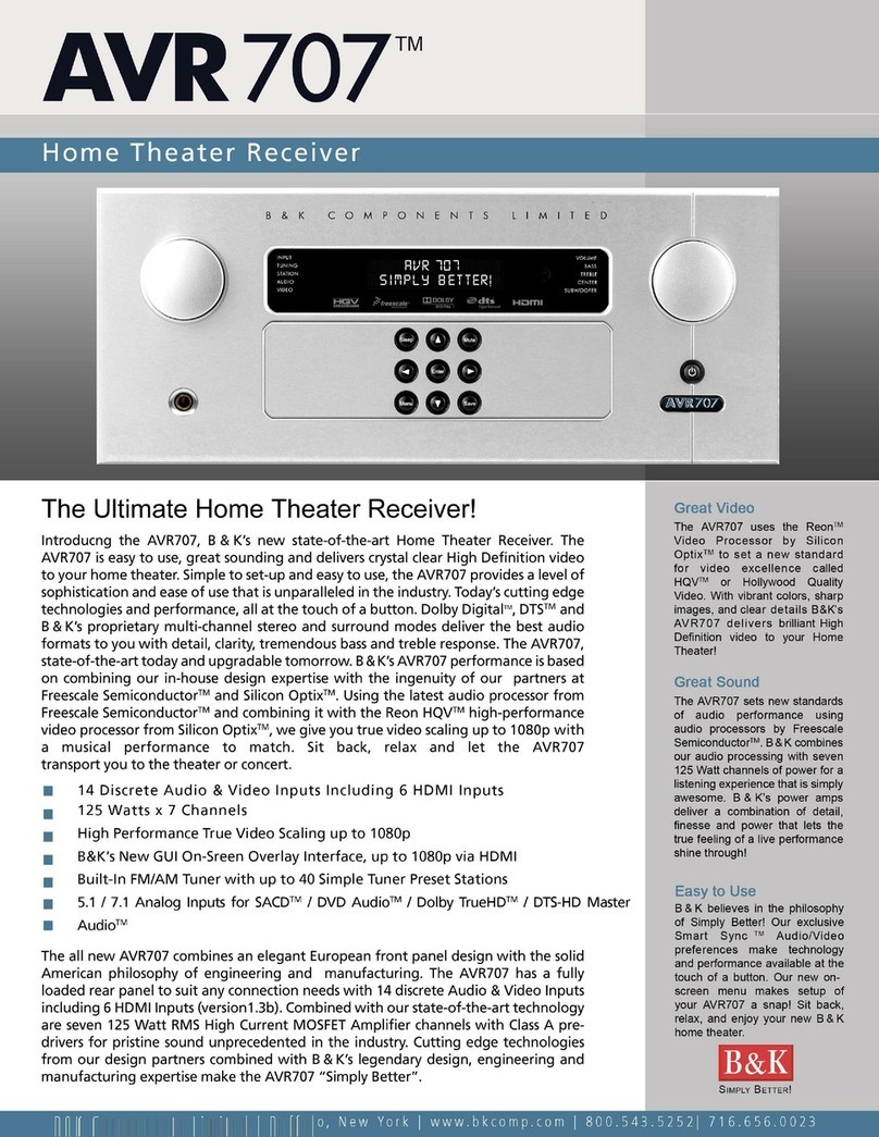
B&K AVR 707 User manual


iii
Thanks for choosing & K Components, Ltd. Our goal is to create friendships and a long
term relationship with our customers and our dealers. Once you buy & K, you’ll never
need to own another brand. We want to earn your loyalty. It’s that simple.
& K began in 1981 with a simple philosophy: Make great sounding audio components
and keep prices reasonable. Today, & K is now, one of the premier manufacturers of
high end audio, multi-room audio / video distribution and home theater components.
Once again, thank you for choosing & K Components, Ltd. We know you have many
choices and hope you’ll continue to think of us for all your home audio and video needs.
We appreciate your business.

iv
Warranty
USER MANUAL - AVR 705 and AVR 707
© 2008 &K Components Ltd. All rights reserved.
The information in this manual is copyright protected. No part of this manual may be copied or reproduced in any form without prior written consent from &K Components, Ltd.
&K Components Ltd. SHALL NOT E LIA LE FOR OPERATIONAL, TECHNICAL OR EDITORIAL ERRORS/OMISSIONS MADE IN THIS MANUAL. The information in this man-
ual is subject to change without prior notice.
Limited Warranty
& K Components Ltd., referred to herein as &K, warrants your & K equipment against all defects in material and workmanship for a period of five years from the date of purchase. This warranty applies
only to the original purchaser and only to equipment in normal residential use and service. Defective equipment must be returned to & K , prepaid, accompanied by proof of purchase and sufficient pay-
ment to cover the cost of return shipping and handling, and will be repaired or replaced at the discretion of & K whose decision as to the method of reparation will be final.
This warranty shall not apply to any equipment which is found to have been improperly installed, incorrectly fused, misused, abused, or subjected to harmful elements, used in any way not in accordance
with instructions supplied with the unit, or to have been modified, repaired or altered in any way without the expressed, written consent of &K. This warranty does not apply to the cabinet or appearance
items such as the faceplate or control buttons, nor does it cover any expenses incurred in shipping the unit to and from the manufacturer's service department.
This warranty on & K Components, Ltd. products is NOT VALID if the products have been purchased from an unauthorized dealer or an E-tailer or if the original factory serial number has been removed,
defaced or replaced in any way. &K Components, Ltd. sells its products through authorized dealers in order to ensure that consumers obtain proper dealer service and support. uying from an author-
ized & K Components, Ltd. dealer insures that you have a FACTORY WARRANTY on your & K Components, Ltd. product. If you have any questions concerning your Factory Warranty call
& K Components, Ltd. at 716-656-0026.
Upgradeability : & K is one of the first manufacturers in the audio/video industry to consistently offer software and hardware upgrades to its processing of audio signals. Through upgrades &K delivers
exceptional value to its customers. ut what is "upgradeability"? Upgradeability is not a guarantee; we define it as a philosophy of designing and manufacturing products so that as audio technology evolves,
& K can provide enhancements and improvements to its products that are economically viable.
THE EXPRESS FACTORY WARRANTY HEREIN CONTAINED IS IN LIEU OF ANY AND ALL OTHER WARRANTIES, EXPRESSED OR IMPLIED, INCLUDING ANY WARRANTY OF MERCHANTA ILI-
TY, UPGRADEA ILITY OR OF FITNESS FOR ANY PARTICULAR PURPOSE. &K COMPONENTS, LTD. SHALL NOT UNDER ANY CIRCUMSTANCES E LIA LE FOR DAMAGES, INCLUDING SPE-
CIAL, INCIDENTAL, EXEMPLARY, PUNITIVE OR CONSEQUENTIAL DAMAGES ARISING OUT OF OR IN CONNECTION WITH THE PURCHASE, USE OR PERFORMANCE OF ANY & K PRODUCT.
This warranty gives you specific legal rights. You may also have other rights which vary from State to State. Some States do not allow the exclusion or limitation of incidental or consequential damages and
the foregoing exclusions may not apply to you.
No agent, representative, dealer or employee of &K has the authority to increase or alter the obligations or terms of this warranty.
Returning Equipment
No equipment may be returned to & K Components Ltd. without a RETURN AUTHORIZATION (RA). Should you find it necessary to return equipment to & K , for any reason, a RETURN AUTHORIZA-
TION (RA) number must be issued by &K in respect to the equipment being returned. You may request an RA number by calling & K at the numbers below. We will need the following information to
issue your RA number. Please have it ready before you call.
1. Your name, address, and phone number.
2. The model and serial number of the equipment being returned.
3. A description of the problem being experienced.
4. Your sales receipt.
Your call will be referred to a Technical Service Representative who will work with you to resolve the problem. If it is determined that the unit must be returned for repair, an RA number will be issued.
SIMPLY ETTER! is a registered trademark of & K Components, Ltd. Manufactured under license from Dolby Laboratories. "Dolby", "Surround EX", “Pro Logic” and the double-D symbol are trademarks
of Dolby Laboratories. Manufactured under license from Digital Theater Systems, Inc. US Pat. No.5,451,942, 5,956,674, 5,974,380, 5,978,762, 6,487,535 and other U.S and worldwide patents issued and
pending. “DTS”, "DTS-ES" and "Neo:6" trademarks of Digital Theater Systems, Inc. Copyright 1996, 2003 Digital Theater Systems, Inc. All Rights Reserved. Freescale®, Freescale name and logo are reg-
istered trademarks of Freescale Semiconductor Inc. All Rights Reserved.

v
Table of Contents
Introduction / Overview .......................................................................................................................................................1
AVR 707 Features ...............................................................................................................................................................2
AVR 707 Front Panel ..........................................................................................................................................................3
AVR 707 Rear Panel ...........................................................................................................................................................4
Quick Start Considerations..................................................................................................................................................6
Connection Overview ..........................................................................................................................................................7
Video Inputs - Hardware Connections ................................................................................................................................9
Video Input Connection - HDMI.....................................................................................................................................9
Video Input Connection - Component Video .................................................................................................................9
Video Input Connection - S-Video .................................................................................................................................10
Video Input Connection - Composite Video...................................................................................................................10
Video Outputs - Hardware Connections..............................................................................................................................11
Video Output Connection - HDMI ..................................................................................................................................11
Video Output Connection - Component Video ..............................................................................................................11
Video Output Connection - Component Video Record Output ......................................................................................11
Audio Inputs - Hardware Connections ................................................................................................................................12
Audio Input Connection - HDMI.....................................................................................................................................12
Audio Input Connection - Optical Digital........................................................................................................................12
Audio Input Connection - Coax Digital...........................................................................................................................12
Audio Input Connection - Stereo Analog........................................................................................................................13
Audio Input Connection - Multi-channel Analog 5.1 or 7.1 ............................................................................................13
Audio Input Connection - alanced Input ......................................................................................................................13
Audio Input Connection - AES-E U Digital ...................................................................................................................13
Audio Output - Hardware Connections ...............................................................................................................................14
Audio Output Connection - Unbalanced ........................................................................................................................14
Audio Output Connection - Speakers ............................................................................................................................14
Audio Output Connection - Subwoofer ..........................................................................................................................15
Audio Output Connection - Optical Digital Record ........................................................................................................15
Audio Output Connection - Coax Digital Record ...........................................................................................................15
Audio Output Connection - Analog Record....................................................................................................................15
Configuration and Control - Hardware Connections ...........................................................................................................16
Ethernet Communication ...............................................................................................................................................16
RS-232 Communication.................................................................................................................................................16
US Communication......................................................................................................................................................16
Keypad / IR - Hardware Connections .................................................................................................................................17
Flasher Outputs / All IR Output / IR Input ......................................................................................................................17

vi
Table of Contents
IR Chain Connection......................................................................................................................................................17
Keypad Connection........................................................................................................................................................17
Control I/O and Antenna - Hardware Connections .............................................................................................................18
Control Output / Amp Enable.........................................................................................................................................18
Control Input ..................................................................................................................................................................18
AM / FM Antenna ...........................................................................................................................................................18
Restore ..........................................................................................................................................................................18
HQV Video Processing........................................................................................................................................................19
Temporal Noise Reduction.............................................................................................................................................19
Detail Enhancement.......................................................................................................................................................19
lock Noise Reduction...................................................................................................................................................19
Mosquito Noise Reduction.............................................................................................................................................19
Chroma Transient Improvement ....................................................................................................................................20
Luma Enhancement.......................................................................................................................................................20
Aspect Control ...............................................................................................................................................................20
Aspect Ratios 4x3 (1:33:1) Formats on 16x9 (1:78:1) Screen ...........................................................................................21
Aspect Ratios Variation 4x3 (1:33:1) Formats on 16x9 (1:78:1) Screen ............................................................................22
Aspect Ratios 16x9 (1:78:1) Formats on 16x9 (1:78:1) Screen .........................................................................................23
Aspect Ratios Variation 16x9 (1:78:1) Formats on 16x9 (1:78:1) Screen ..........................................................................25
Aspect Ratios - 16x9 (1:78:1) Formats on 2:35:1 Screen with Anamorphic Lens ..............................................................26
Operation and Control.........................................................................................................................................................27
SR 10.1 Remote Control Guide.....................................................................................................................................27
Master Power On / Off...................................................................................................................................................28
On / Off / Sleep ..............................................................................................................................................................28
Source Selection............................................................................................................................................................28
Adjusting Volume ...........................................................................................................................................................28
Adjusting Center / Rear / Subwoofer Level ...................................................................................................................28
Adjusting Audio EQ........................................................................................................................................................29
Adjusting Audio ass / Treble Equalization ...................................................................................................................29
Adjusting Video rightness............................................................................................................................................29
Adjusting Video Contrast ...............................................................................................................................................29
Adjusting Video Color ....................................................................................................................................................29
Adjusting Video Hue ......................................................................................................................................................29
Adjusting Video Aspect ..................................................................................................................................................29
Adjusting Video Sharpness............................................................................................................................................29
Adjusting Video Stretch..................................................................................................................................................30

vii
Table of Contents
Adjusting Video Zoom....................................................................................................................................................30
Adjusting Video Luma Enhancement.............................................................................................................................30
Adjusting Video Detail Enhancement ............................................................................................................................30
Adjusting Video Temporal Noise Reduction...................................................................................................................30
Adjusting Video Mosquito Noise Reduction...................................................................................................................30
Adjusting Video lock Noise Reduction.........................................................................................................................30
Adjusting Video Luma Transient Improvement..............................................................................................................30
Adjusting Video Chroma Transient Improvement ..........................................................................................................30
AM / FM Tuner Operation ..............................................................................................................................................31
Headphone Operation....................................................................................................................................................31
Control Out On / Off.......................................................................................................................................................31
Audio / Video / Tuner Preference Selection...................................................................................................................32
Front Panel Display Operation.......................................................................................................................................33
Front Panel Display - Abbreviations ..............................................................................................................................33
Front Panel Display - Digital Audio Input Status .................................................................................................................34
Digital Multi-channel itstreams.....................................................................................................................................34
Front Panel Display - Analog Audio Input Status ................................................................................................................35
Analog, PCM, DD 2.0 itstreams ..................................................................................................................................35
Audio Modes and Speaker Selections ................................................................................................................................36
Audio Mode Usage ........................................................................................................................................................36
On Screen Display (OSD) Format ......................................................................................................................................38
OSD - Unit Operation - Audio ........................................................................................................................................39
OSD - Unit Operation - Video & Tuner ..........................................................................................................................40
OSD - System Settings - Audio .....................................................................................................................................41
OSD - System Settings - Video .....................................................................................................................................42
OSD - System Settings - Control...................................................................................................................................43
OSD - Input Settings......................................................................................................................................................44
OSD - Preference Settings - Audio................................................................................................................................45
OSD - Preference Settings - Video & Tuner..................................................................................................................46
OSD - Unit Information ..................................................................................................................................................47
Software Setup....................................................................................................................................................................48
PC - Hardware Connections ...............................................................................................................................................49
Ethernet Communication ...............................................................................................................................................49
Serial Connection...........................................................................................................................................................49
KcSuite Setup and Overview............................................................................................................................................50
Connecting and using the Virtual Mode.........................................................................................................................50

viii
Table of Contents
KcSuite System Settings - Audio ......................................................................................................................................52
Speaker Size..................................................................................................................................................................52
Speaker Level ................................................................................................................................................................53
Speaker Location ...........................................................................................................................................................53
Crossover and LFE........................................................................................................................................................54
Room Equalization.........................................................................................................................................................54
Room Resonance (Notch Filters) ..................................................................................................................................55
Notch Filter Setup ..........................................................................................................................................................56
Audio Assignment ..........................................................................................................................................................57
Max Level / Surround Mode ..........................................................................................................................................57
KcSuite System Settings - Video......................................................................................................................................58
Video Settings................................................................................................................................................................58
KcSuite System Settings - Control ...................................................................................................................................59
Zone ID ..........................................................................................................................................................................59
Control In / Page Event .................................................................................................................................................59
RS-232 Control Port ......................................................................................................................................................59
Security Options.............................................................................................................................................................60
Plug and Play Timing .....................................................................................................................................................60
Front Panel Settings ......................................................................................................................................................61
Network Settings............................................................................................................................................................61
Power On Settings.........................................................................................................................................................62
Memory ..........................................................................................................................................................................62
KcSuite Input Settings - Audio ..........................................................................................................................................63
Audio Input.....................................................................................................................................................................63
KcSuite Input Settings - Video..........................................................................................................................................64
Video Input.....................................................................................................................................................................64
Audio Preference Guide......................................................................................................................................................65
Video Preference Guide......................................................................................................................................................66
Tuner Preference Guide......................................................................................................................................................67
Updating Firmware ..............................................................................................................................................................69
Specifications ......................................................................................................................................................................70

ix
Safety Precautions
To prevent fire or shock hazard, do not expose this unit to rain or moisture. Care should be taken to prevent objects or liquid from entering the enclo-
sure. Never handle the power cord with wet hands.
•The lightning flash with arrowhead within a triangle is intended to alert the user of the presence of uninsulated "dangerous voltage" within the product's
enclosure that may constitute a risk of electric shock to you.
•The exclamation point within a triangle is intended to alert the user of the presence of important operating and maintenance (servicing) instructions in
the literature accompanying the unit.
•Caution: To prevent the risk of electric shock, do not remove cover. No user-serviceable parts inside. Refer servicing to qualified service personnel.
•If an outdoor antenna is installed, be sure it is grounded to provide some protection against voltage surges and built up static charges. Keep outdoor
antennas away from power lines.
•Unplug the receiver from the AC outlet when plugging in or unplugging cables, when left unused for an extended period of time, when moving the
receiver, or when you suspect lightning in your area.
•Prevent damage to the power cord. Replace the power cord if it becomes damaged in any way. Always grasp the plug on the power cord when plugging
or unplugging the receiver from the AC outlet.
•Your system may produce sound levels capable of causing permanent hearing loss. Do not operate for extended periods of time at high volume levels.
•Protect the receiver from impact and place the receiver on a level surface.
•The receiver is equipped with raised feet to provide ventilation, reduce acoustic feedback, and protect against scratching the surface the unit is resting
on. &K advises against removing the feet.
•Do not stack anything on top of the receiver (processor, source, etc.) Leave a minimum of 3" clearance from above the top of the receiver.
•The receiver should be located away from sources sensitive to heat.
•Do not perform any internal modifications to the receiver.
•Always connect the receiver's power cord to a dedicated AC outlet for normal operation.
•If young children are present, adult supervision should be provided until the children are capable of following all rules for safe operation.
•Mistaking CONTROL OUTPUT or IR INPUT connectors for audio/video inputs or outputs may damage your receiver or other components.
•It is recommended that the system speaker impedance seen by the amplifier channels of the receiver not fall below 4 ohms. est amplifier thermal sta-
bility is achieved when the it operates into a 4 ohms or greater speaker load. The nominal impedance of most home speakers range between 4 and 8
ohms. Two 8 ohm speakers in parallel is equal to a 4 ohm (system impedance).
The receiver should be serviced by qualified personnel when:
A. The receiver is not functioning properly.
. Objects have entered the chassis.
C. The receiver was exposed to rain or any other type of moisture.
D. The receiver was dropped, or the chassis is damaged.
Warning

1
Introduction / Overview
The Heart & Soul of your A/V System!
& K’s AVR 707, our new state-of-the-art Home Theater Receiver. The AVR 707 is easy to use, great sounding and delivers crys-
tal clear high definition video to your home theater. Simple to set-up and easy to use, the AVR 707 provides a level of sophistication and
ease of use that is unparalleled in the industry. Today’s cutting edge technologies and performance, all at the touch of a button. Dolby
Digital, DTS and & K’s proprietary multi-channel stereo and surround modes deliver the best audio formats to you, with detail, clarity,
and tremendous bass and treble response. The AVR 707, state-of-the-art today and upgradable tomorrow.
& K’s AVR 707 performance is based upon combining our in-house design expertise with that of our engineering partners at
Freescale Semiconductor and Silicon Optix. The AVR 707 uses Freescale’s latest audio processor and combines it with Silicon Optix’s
hi-performance video processor, the Reon HQV Processor, together we give you true video scaling up to 1080p with a musical perform-
ance to match. Sit back, relax and let the AVR 707 transport you to the theater or concert.
The all new AVR 707, an elegant yet functional European front panel design combined with the best nuts and bolts can-do
American design, engineering and manufacturing expertise. The AVR 707 has a fully loaded rear panel with 14 discrete Audio & Video
Inputs, including 6 HDMI Inputs (HDMI 1.3b), 7.1 RCA surround outputs and seven 125 watt amplifier channels. Combine all these con-
nections with our state-of-the-art technology inside the AVR 707 and you get pristine sound and picture quality unprecedented in the
industry. Cutting edge technologies from our design partners combined with & K’s legendary design, engineering and manufacturing
expertise make the AVR 707 “Simply etter”.

2
AVR 707 Features
14 Discrete Audio & Video Inputs
1 AES / E U Digital Audio (XLR) Input
8 Analog Audio Inputs (excluding 5.1 or 7.1 inputs)
1 alanced Audio (XLR) Input
1 Multi Channel Analog 5.1 or 7.1 Input for analog DVD Audio / Dolby TrueHD / DTS-HD Master Audio
16 Digital Audio Inputs (8 Optical / 8 Coax Digital)
8 Component / Composite / S-Video Inputs and 2 Component Monitor Outputs
6 HDMI Inputs (HDMI 1.3b) with support for Multi-channel PCM and SACD
Dolby TrueHD / DTS-HD Master Audio Decoding (future upgrade)
1 HDMI Output (HDMI 1.3b)
8 Unbalanced (RCA) Outputs
8 balanced (XLR) Outputs
True upscaling of HDMI, Component, Composite and S-Video Inputs up-to 1080p over HDMI and Component (1080i max)
CinemaScope Scaling for 2.35 Aspect Ratio Screen Support (additional Cinema Lens Required)
1 1/8” mini-jack 12VDC Control Port
1 1/8” mini-jack 12VDC Amp Enable
&K’s GUI On-Screen Interface with Overlays up to 1080p via HDMI and Component (1080i max)
Full 2-Way RS-232 / Ethernet Serial Setup, Command and Control
Software Upgrade Capability
uilt-In 14 Source Discrete IR Routing
uilt-In AM/FM Tuner with Simple Tuner Preset Stations
New Smart Sync &K Programmable Audio and Video Preferences
US 2.0 interface (future upgrade)

1. Left Hand Knob - The left selector knob is a rotary encoder with the primary purpose of A/V input source selection. The knob serves multiple functions. Pushing
in on the the knob will scroll through the options to control or select Input Source, AM/FM Tuning, AM/FM Station, Audio Preference or Video Preference. Rotating
the knob will change the highlighted function.
2. Display - The receiver contains a 16 character by 2 row display. It will indicate current status of the receiver and any changes being performed.
3. Right Hand Knob - The right selector knob is a rotary encoder with the primary purpose of audio volume adjustment. The knob serves multiple functions.
Pushing in on the the knob will scroll through the options to control Master Volume, ass, Treble, Center Volume or Subwoofer Volume. Rotating the knob allows
changing of the highlighted function.
4. Main power switch - Removes all power to the receiver. Normal operation of the receiver requires the power switch to remain on. Use the SLEEP button for
daily on and off of the receiver. SLEEP places the unit in standby mode, which allows turning back on with the remote control. Turn the receiver off using the
Main Power switch when the receiver is not used for extended periods of time or when connecting or disconnecting hardware connections.
5. Front panel buttons - Front panel buttons serve the following functions:
Sleep - Toggles the unit in and out of standby mode (ON or OFF).
Mute - Toggles the units volume in and out of the mute state (ON or OFF).
Menu - Press to enter in and out of the menu system.
Save - Save the selected setting such as a Preference or Menu option.
Enter - Pressing allows selection of the desired function while in the menu system. Additionally used for Recall and Save operations.
Arrows - Left, Right, Up and Down arrows allow navigation through the menu system.
6. Headphone Jack - Headphones having a standard 1/4” (6.3mm) stereo plug may be connected to the headphone output.
3
AVR 707 Front Panel
3
2
1
64
5

1. AC Fuse Holder - Holds the AC line fuse. Replace only with same type and value 2A fast blow. Note: The voltage rating label is located on the AC fuse holder
cover plate.
2. AC Input Receptacle - For attaching the supplied AC power cord to the unit.
3. HDMI Inputs/Output - 6 input and 1 output High Definition Multimedia Interface (HDMI) connections. Connections carry both the digital audio and digital video
signal simultaneously with output resolutions of 720p, 1080i or 1080p - default set to 1080i.
4. Three-position Phoenix Adapter - Phoenix connection for using a Page / Event system with the receiver.
5. Keypad Connection and IR Daisy Chaining - RJ-45 Keypad Connection provides a 12VDC power, common ground, RS-232 transmit, IR Data IN, and 12V
control output trigger. The receiver will support up to 5 daisy-chained &K keypads. The IR Chain connection allows linking the receiver to a CT product for full
two-way communication.
6. IR Flashers, All IR Output and IR In - 1/8" Mini-Jack (Tip + Ring -) connections for IR routing. Flasher outputs allow routing of up to 14 source components.
All IR Output will direct all IR information being received by the unit from the Keypad input, front panel or the 1/8" Mini-Jack IR input. IR Input allows an IR sig-
nal to be sent into the unit in order to control the receiver or for routed pass-thru control of a connected source component.
AVR 707 Rear Panel
35
1
4678 9
10
11
12
13
14
15
18 16
17
2

5
AVR 707 Rear Panel
7. AVR 705 Speaker Outputs - 5-Way binding posts supply power to the Front, Surround and Center channel speakers.
8. AVR 707 Speaker Outputs - 5-Way binding posts supply power to the Front, Surround, Center and ack channel speakers.
9. Component Video Inputs - A total of 8 component video inputs for standard and high definition video signals. Composite video directly connects to the red
RCA. S-Video is Y - green RCA, C - blue RCA using supplied S-VIDEO to RCA adapter.
Component Video Outputs - Scaled video output may be set to 720p, 1080i - default set to 1080i.
10. Digital Optical Audio Inputs - A total of 8 optical digital audio inputs for connecting optical digital audio signals from the source to the receiver.
Digital Optical Audio Output - A single optical digital audio output for use with another audio device. The audio output is currently sourced from the selected
audio input.
11. RCA Analog Audio Inputs - A total of 8 stereo analog RCA inputs for use as standard input pairs. Optional Multi-Channel analog support for use with inputs
5-7 (5.1), 5-8 (7.1). Configuration may be set and viewed using the menu or KcSuite.
RCA Analog Record Output - A stereo pair of analog RCA outputs for use with an analog recording device.
12. RCA Surround Outputs - 7.1 Surround outputs for driving external power amplifiers or powered speakers.
13. Coax Digital Audio Inputs - A total of 8 coax digital audio inputs for connecting coax digital audio signals from the source to the receiver.
Coax Digital Audio Output - A single coax digital audio output for use with another audio device. The audio output is currently sourced from the selected audio
input.
14. FM/AM Tuner - Respective connections for attaching the included AM and FM tuner antennas for internal tuner reception.
15. RS-232 Control Port - RS-232 RJ-45 input/output for computer interface and RS-232 serial controller applications.
Ethernet Control Port - Ethernet RJ-45 input for flashing the software in the receiver. Also used for computer interface and Ethernet control applications.
16. USB 2.0 - US 2.0 connection for use of configuring and controlling the receiver. Feature is not enabled at this time. Please see www.bkcomp.com for updates,
when available.
17. Restore - Sometimes it is advisable to restore the unit to a factory default state in order to clear problematic system operation. A factory restore will clear all
system settings, Audio and Video Preferences and Serial Macros. Restore may be selected by simultaneously pressing the front panel Sleep, Up and Right
Encoder Knob [Master Volume]. Alternately, pushing in the rear panel button for 5 seconds will restore all settings to factory default.Feature is not enabled at
this time. Please see www.bkcomp.com for updates, when available.
18. Control Output - 1/8” Mono Mini-jack (Tip+ Ring -) source of 12VDC 100mA output for controlling external devices, such as amplifiers and projection screens.
A remote control CTRL+ "Control On" command will turn on 12VDC and “CTRL-” will turn off 12VDC. Additional control and control is available using RS-232
and Ethernet KC-DIP.
Amp Enable - 1/8” Mono Mini-jack (Tip+ Ring -) source of 12VDC 100mA for use with automatically controlling an external device while not in sleep.

6
Quick Start Considerations
Your &K receiver is pre-programmed for ease of operation right out of the box. In general, there is minimal setup required to start using your new A/V receiver. To
quickly setup and begin operating your receiver, follow these quick steps:
1 Start with all AC power cords unplugged from their designated AC outlet.
2 From each source device, connect the A/V cables to the appropriate A/V SOURCE INPUTS on the receiver’s back panel.
3 Connect the speaker cables from the receiver’s SPEAKER OUTPUTS to the appropriate speakers.
4 Connect the appropriate video cables from the receiver’s video OUTPUTS to the video monitor’s input(s).
5 Plug each AC power cord into its designated AC outlet.
6 Turn on all A/V sources. Turn on the main power switch on the front of each unit. Press the ON/SLEEP button on the front panel of the receiver, or the ON but-
ton of the remote.
7 Select a source using the front panel source control of the receiver or with the SR10.1 remote control.
The rest of this manual will give further insight into the many aspects of your new receiver. Some additional installation considerations should be noted as fol-
lows:
•It is important that your electronic equipment be located where there is proper ventilation. Failure to ventilate your receiver could result in erratic operation
and possible failure caused by overheating. A minimum of 3” clearance should be maintained above the receiver. Do not place items directly on top of the receiv-
er. Do not place flammable items on, around or near the A/V equipment (Curtains, paper, etc.).
•&K supports various software programs that are able to aide in the setup process of the receiver/ preamplifier, SR10.1 remote and CK1.2 Keypad. This
software is available online at &K’s website at www.bkcomp.com or by request from &K’s customer service. The setup software is easy to use and is intend-
ed to simplify the setup process of your new &K products.
•Configure a system diagram of all components that are to be connected into the system. The receiver has a total of 14 Audio and Video inputs. The back
panel is labeled In 1 to In 8 for Component Video, S-Video, Composite Video, Analog Audio Left + Right Inputs, Digital Coaxial and Digital Optical sources, in
most cases it is possible to connect any source to any input. HDMI inputs are labeled In 9 to In 14. You may assign Audio Inputs, In 1 through In 8(Analog or
Digital) to a HDMI Video Input. You may not assign the HDMI Audio to Video Inputs, In 1 through In 8. The source name by default is set to In1, In 2, In 3 etc...
The Inputs may be renamed in the Menu to reflect the source name, ex. In 9 may be change to Blu-Ray. The renamed source input name will appear on the
receiver’s front panel and the OSD (On Screen Display). The source input name on the remote or keypad may be relabeled to match the source equipment that
is being used.
•Determine the type of cable that is needed. Keep in mind that the quality of the cabling that is used may make a difference in the overall audio and video
quality. Try to keep interconnecting cable runs as short as possible. When routing cables between equipment, be sure to keep AC cables separate from audio
cables. It is a good idea to bundle like cables together to keep interference (noise) to a minimum.
•It is a good idea to label each cable with a name or number at both ends when allocating each cable. Have all the cables you need before you begin the
installation because it is inconvenient to run to the store when you are excited to hear what the system will sound like.
•Plan enough cable length and space to allow future access to the back panel.
•For best tuner reception, make sure the antenna is several feet away from the receiver and any other equipment that may produce high frequency interfer-
ence such as personal computers, CD players, halogen lamps, etc.
•For best performance it is recommended that a dedicated AC power line or supply be used. If the equipment is installed in a rack, be sure to insulate the
equipment from the rack itself.

7
Connection Overview

8
Connection Overview

9
Video Input Connection - Component Video
The &K surround receiver provides eight sets of component video inputs. Each component input corresponds to a set of stereo analog
inputs, optical digital inputs and coax digital inputs. For example, Component video input 8 would correspond to Analog Stereo input 8,
Optical digital input 8 and Coax digital input 8. Shown above is a component video source going into Input 8 on the &K.
Video Input Connection - HDMI
The &K surround receiver provides 6 HDMI A/V inputs. HDMI carries both audio and video, B&K allows options to process audio and
video separately (please see the menu setup for further options). To connect an HDMI video source to the &K, connect the HDMI cable
to the HDMI output on the source piece. Then connect the other end of the cable into the corresponding HDMI input on the receiver.
Shown is an HDMI output on the source piece going into Input 9 on the &K.
Video Inputs - Hardware Connections

10
Video Inputs - Hardware Connections
Video Input Connection - Composite Video
The &K surround receiver provides eight sets of component video inputs. These inputs may be used to up-convert a composite video
signal to go into the component input. Connect the composite video output on the source piece using an RCA cable to the red colored
input on the &K. Shown is a composite video source with an RCA connection going into the red RCA input of Input 1.
Video Input Connection - S-Video
The &K surround receiver provides eight sets of component video inputs. These inputs may be used with the S-Video to RCA adapter
that is supplied with the receiver in order to up-convert an S-Video signal to go into the component input. Connect the one end of the S-
Video to RCA adapter to the S-Video output on the source piece. Then connect RCA cables from the adapter to the corresponding col-
ored inputs on the &K. Shown is an S-Video source connected to the S-Video to RCA adapter with RCA connections going into the
blue (C) and green (Y) RCA inputs of Input 3.

11
Video Output Connection - Component Video Record Output
The component video record output connection on the receiver standardly carries High Definition video. However, for use with recording
purposes, &K supports Component, Composite or S-Video on this output. While set to RECORD OUT, any selected video source on
the receiver is scaled to Composite or S-Video as set under System Video setup. Note: The system setup menu will NOT be displayed
on the this output during record mode operation. During standard video processing, the only video outputs available are
HDMI and/or Component video. If your monitor or television does not have support for these connections, please con-
tact your local authorized B&K dealer.
Video Output Connection - Component Video
The component video output connection on the receiver carries High Definition video to
your television or monitor. To connect an component video output from the &K, connect
the three RCA component video cables to the corresponding component video outputs on
the &K. Then connect the other ends of the cables into the corresponding component
video inputs on your television or monitor. Shown is the component video output on the
&K going to the component video input on a monitor.
Video Output Connection - HDMI
The HDMI output connection on the receiver carries High Definition video to your television or monitor. To connect an HDMI video out-
put from the &K, connect the HDMI cable to the HDMI output on the &K. Then connect the other end of the cable into the correspon-
ding HDMI input on your television or monitor. Shown is the HDMI output on the &K going to
the HDMI input on a monitor.
Video Outputs - Hardware Connections
Other manuals for AVR 707
1
Table of contents
Other B&K Receiver manuals
